球阀安装标准手册
- 格式:doc
- 大小:183.00 KB
- 文档页数:6
球阀的安装方法内容来源自网络一、安装前的准备1、球阀前后管线已准备好。
前后管道应同轴,两法兰密封面应平行。
管道应能承受球阀的重量,否则管道上必须配有适当的支撑。
2、把阀前后管线吹扫干净,清除掉管道内的油污、焊渣和一切其它杂质。
3一、安装前的准备1、球阀前后管线已准备好。
前后管道应同轴,两法兰密封面应平行。
管道应能承受球阀的重量,否则管道上必须配有适当的支撑。
2、把阀前后管线吹扫干净,清除掉管道内的油污、焊渣和一切其它杂质。
3、核对球阀的标志,查明球阀完好无损。
将阀全开全闭数次证实其工作正常。
4、拆去球阀两端连接法兰上的保护件。
5、检查阀孔清除可能有的污物,然后清洗阀孔。
阀座与球之间即使仅有微小颗粒的异物也可能会损伤阀座密封面。
二、安装1、把阀装上管线。
阀的任何一端都可装在上游端。
用手柄驱动的阀可安装在管道上的任意位置。
但带有齿轮箱或气动驱动器的球阀应直立安装,即安装在水平管道上,且驱动装置处于管道上方。
2、阀法兰与管线法兰间按管路设计要求装上密封垫。
3、法兰上的螺栓需对称、逐次、均匀拧紧。
4、连接气动管线(采用气动驱动器时)。
三、安装后的检查1、操作驱动器启、闭球阀数次,应灵活无滞涩,证实其工作正常。
2、按管路设计要求对管道与球阀间的法兰结合面进行密封性能检查。
采购前阀门选型的步骤和依据:在流体管道系统中,阀门是控制元件,其主要作用是隔离设备和管道系统、调节流量、防止回流、调节和排泄压力。
由于管道系统选择最适合的阀门显得非常重要,所以,了解阀门的特性及选择阀门的步骤和依据也变得至关重要起来。
阀门行业到目前为止,已能生产种类齐全的闸阀、截止阀、节流阀、旋塞阀、球阀、电动阀、隔膜阀、止回阀、安全阀、减压阀、蒸汽疏水阀和紧急切断阀等12大类、3000多个型号、4000多个规格的阀门产品;最高工作压力为600MPa,最大公称通径达5350mm,最高工作温度为1200℃,最低工作温度为-196℃,适用介质为水、蒸汽、油品、天然气、强腐蚀性介质(如浓硝酸、中浓度硫酸等)、易燃介质(如笨、乙烯等)、有毒介质(如硫化氢)、易爆介质及带放射性介质(金属钠、-回路纯水等)。
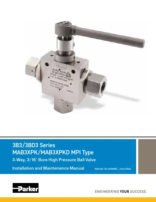
" Bore High Pressure Ball ValveManual: 02-0036ME | June 2022Operation & Maintenance Manual | 06/2202-0036ME : 3B3/3BD3/MAB3X Series Ball Valve2FAILURE, IMPROPER SELECTION OR IMPROPER USE OF THE PRODUCTS AND/OR SYSTEMS DESCRIBED HEREINOR RELATED ITEMS CAN CAUSE DEATH, PERSONAL INJURY AND PROPERTY DAMAGE.This document and other information from Parker Hannifin Corporation, its subsidiaries and authorized distributors provide product and/or system options for further investigation by users having technical expertise. It is important that you analyze all aspects of your application and review the information concerning the product or system in the current product catalog.Due to the variety of operating conditions and applications for these products or systems, the user, through its own analysis and testing, is solely responsible for making the final selection of the products and systems and assuring that all performance, safety and warning requirements of the application are met.The products described herein, including without limitation, product features, specifications, designs, availability and pricing, are subject to change by Parker Hannifin Corporation and its subsidiaries at any time without notice.ALL PARKER VALVES MUST PASS A RIGID OPERATIONAL AND LEAKAGE TEST BEFORE LEAVING THE FACTORY. IT IS RECOMMENDED AFTER ANY REASSEMBLY, THE VALVE SHOULD BE TESTED BY THE USER FOR OPERATION AND LEAKAGE. IF THESE INSTRUCTIONS ARE NOT FULLY COMPLIED WITH, THE REPAIRED PRODUCT MAY FAIL AND CAUSE DAMAGE TO PROPERTY OR INJURY TO PERSONS. PARKER HANNIFIN CANNOT ASSUME RESPONSIBILITY FOR PERFORMANCE OF A CUSTOMER SERVICED VALVE.Live Chat Support is available from /IPD when the Chat icon “ ” is visible on screen.Parker Instrumentation Products Divison (IPD)Model #: Serial #:Drawing #:Order #:Mfg. Date:Complete information above for future reference.NOTES:02-0036ME : 3B3/3BD3/MAB3X Series Ball ValveOperation & Maintenance Manual | 06/223 Product Drawings3B3/3BD3/MAB3* Parts List and Material ...........................................................................4 3B3/3BD3/MAB3* Dimensional View .................................................................................5 3B3/3BD3/MAB3* Panel Mounting View .. (5)Installation Information1.0 Introduction ......................................................................................................................6 2.0 Precautions ...................................................................................................................... 6 3.0 Installation ....................................................................................................................... 6 4.0 Installation Summary Chart & Repair Kit Identification . (7)5.0Assembly (8)Maintenance Information6.0Maintenance Notes (9)Note: *= 3B3/3BD3 Series and MAB3XPK/MAB3XPKD MPI TypeT able of ContentsPageOperation & Maintenance Manual | 06/2202-0036ME : 3B3/3BD3/MAB3X Series Ball Valve43B3/3BD3/MAB3* Series: Parts List and MaterialMaterial of Construction:Detail ADetail A1513211622125341711101914920871861202-0036ME : 3B3/3BD3/MAB3X Series Ball ValveOperation & Maintenance Manual | 06/2253B3/3BD3/MAB3* Series: Panel Mounting3B3/3BD3/MAB3* Series: Dimensional View (3/8")Operation & Maintenance Manual | 06/2202-0036ME : 3B3/3BD3/MAB3X Series Ball Valve6Installation InformationSection 1.0IntroductionThe Parker Autoclave Engineers 3B3/3BD3 Series ball valve can be used at pressures up to 15,000 psi with side port pressure inlet and 20,000 psi with bottom port pressure inlet (MPI Type limited to 15,000 psi),depending on the tubing connections and operating temperatures. The maximum operating media pressure at room temperature is etched on the valve body. The curve shown below can be used to find the maximum operating pressure at various media temperatures.Section 2.0PrecautionsHold the seat glands and bottom gland with a wrench when tightening or loosening the tubing connections.Ball valves can trap pressurized media inside the valve. Relieve this pressure by turning the handle to the “half-open” position before disassembling the valve.Section 3.0InstallationRefer to the instruction section of the Parker IPD (Autoclave Engineers) Valves, Fittings, and Tubing Catalog for proper tubing connection installation.Refer to the manufacturer’s literature when using air or electric operators.Parker IPD (Autoclave Engineers) reserves the right to alter the specifications given in this publication in line with our policy of continuous improvement. All general terms and conditions of sale including limitations of our liability, apply to all products and services sold.Pressure Temperature RatingsTemperature ºF (ºC)P r e s s u r e P S I G (B a r )100(38)200(93)300(150)400(204)500(260)0(-18)5000(345)10000(690)15000(1034)1/2" LP ConnectionMP & HP , NPT, QS Connection02-0036ME : 3B3/3BD3/MAB3X Series Ball ValveOperation & Maintenance Manual | 06/227* = Torque wrench not required for PAE Speedbite tube connections. Tighten gland until sleeve begins to grip tubing then 1-1/4 turn.** = Tighten gland nut until sleeve begins to grip tubing. Then 1-1/4 turns.*** = Use Preset Tool. For MPI tighten 1/2 turn in connection. For QSS tighten 1/4 turn in connection.**** = Repair kit part numbers shown above for 316SS material only. Contact Factory for part numbers of optional materials.Section 4.0Installation Summary Chart & Repair Kit Identification8Section 6.0MaintenanceRoutine maintenance consists of tightening the seat glands periodically to compensate for seat wear. With no pressure in the valve, use the following procedures:4.1 Seat Glands4.1.1 Remove lock device from seat glands4.1.2 While holding the seat glands and the bodysecure, loosen the tubing connections4.1.3 With the handle in the “Full Open” position,gradually tighten the glands alternatingfrom one gland to the other in increments of10 in. lbs. (1.12 Nm) until 30 in. lbs. (3.38 Nm)has been reached.Do Not Apply More Than 30 In. Lbs. (3.385 Nm)4.1.4 While holding seat gland secure with a wrench,tighten seat gland locknuts to the valve body.Section 5.0AssemblyGeneral Assembly Procedure for 3/16" Port 3-Way Ball Valve1. Press bottom bearing into bottom gland.2. Install o-ring onto bottom gland and lubricate witho-ring grease.3. Lubricate bottom gland threads with Jet Lube SS301& assemble into bottom port of body so that thegland bottoms out against the body. Then tightengland against the valve body with a wrench.4. Using packing gland, delicately slide the stem sealand backup onto the upper shoulder of stem andlubricate the outside of the seal and ball surfacewith o-ring grease.5. Lubricate the bottom bearing area of the stem witho-ring grease.6. With the stem flat to the left, assemble packinggland, stem and stem seal with backup into thebody center opening until the seal assembly fullyenters the bore of the body.7. Remove packing gland.8. Lubricate both sides of the thrust washer with JetLube SS301 and place over the stem.9. Lubricate the packing gland threads with Jet LubeSS301 and slip the packing gland over the stemand screw into the body until the hole in the ball isaligned with the center of the side ports of the body.Back packing gland out one and a half turns.10. Press seats into seat retainers (using flat faced viseif necessary).11. Assemble 2 belleville washers onto seat retainerwith the inside diameters of the washers face toface.12. Place belleville backup washer on the seat retainersagainst the belleville washers with the large faceof the washer facing the bellevilles.13. Place the small o-ring onto the seat retainer behindthe belleville backup washer and lubricate witho-ring grease.14. Assemble locknut onto seat gland and lubricate theseat gland threads with Jet Lube SS301.15. Install o-rings onto the seat glands and lubricate theo-rings with o-ring grease.16. Press retainer assemblies into the seat glands.17. While keeping the ball in the open position, torqueseat glands into body using 30 in-lbs torque in10 in-lbs alternating increments.18. While holding seat glands in place with a wrench,tighten locknuts against the valve body.19. Hand tighten packing gland.20. Assemble locking piece onto packing gland.¹ MP-50 is a registered trademark of Jet-Lube CorporationOperation & Maintenance Manual | 06/2202-0036ME: 3B3/3BD3/MAB3X Series Ball ValveOperation & Maintenance Manual | 06/22902-0036ME: 3B3/3BD3/MAB3X Series Ball Valve02-0036ME: 3B3/3BD3/MAB3X Series Ball Valve10Operation & Maintenance Manual | 06/2202-0036ME : 3B3/3BD3/MAB3X Series Ball ValveOperation & Maintenance Manual | 06/2211Maintenance Notes02-0036ME June 2022© 2022 Parker Hannifin Corporation | Instrumentation Products Division1005 A Cleaner WayHuntsville, AL 35805 USA Tel: 256.881.2040Fax: /IPDOperation and Maintenance Manual (OM)3B3/3BD3/MAB3X Series Ball ValveParker WorldwideNorth AmericaUSA – Corporate, Cleveland, OH Tel: +1 256 896 3000USA – IPD, Huntsville, AL Tel: +1 256 881 2040*****************USA – IPD, (Autoclave), Erie, PA Tel: +1 814 860 5700*******************CA – Canada, Grimsby, Ontario Tel +1 905-945-2274*********************South AmericaAR – Argentina, Buenos Aires Tel: +54 3327 44 4129 ******************BR – Brazil, Diadema, SP Diadema, SPTel: +55 11 4360 6700******************CL – Chile, Santiago Tel: +56 (0) 2 2303 9640******************MX – Mexico, Toluca Tel: +52 722 275 4200*******************Asia PacificAU – Australia, Dandenong Tel: +61 (0)2 9842 5150******************************CN – China, Shanghai Tel: +86 21 2899 5000*****************************HK – Hong Kong Tel: +852 2428 8008IN – India, MumbaiTel: +91 22 6513 7081-85ID – Indonesia, Tangerang Tel: +62 2977 7900********************JP – Japan, Tokyo Tel: +(81) 3 6365 4020******************KR – South Korea, Seoul Tel: +82 2 559 0400*******************MY – Malaysia, Selangor Tel: +603 784 90 800*******************SG – Singapore,Tel: +65 6887 6300*******************TH – Thailand, Bangkok Tel: +66 2 186 7000*********************TW – Taiwan, Taipei Tel: +886 2 2298 8987*************************VN – Vietnam, Hochi Minh City Tel: +848 382 508 56**********************Europe, Middle East, AfricaAE – UAE, Dubai Tel: +971 4 812 7100********************AT – Austria, Wiener Neustadt Tel: +43 (0)2622 23501-0*************************AT – Eastern Europe, Wiener Neustadt Tel: +43 (0)2622 23501 900****************************AZ – Azerbaijan, Baku Tel: +994 50 2233 458****************************BE/LU – Belgium, Nivelles Tel: +32 (0)67 280 900*************************BG – Bulgaria, Sofia Tel: +359 2 980 1344**************************BY – Belarus, Minsk Tel: +48 (0)22 573 24 00*************************CH – Switzerland, Etoy Tel: +41 (0) 21 821 87 00*****************************CZ – Czech Republic, Klecany Tel: +420 284 083 111*******************************DE – Germany, Kaarst Tel: +49 (0)2131 4016 0*************************DK – Denmark, Ballerup Tel: +45 43 56 04 00*************************ES – Spain, Madrid Tel: +34 902 33 00 01***********************FI – Finland, VantaaTel: +358 (0)20 753 2500*************************FR – France, Contamine s/Arve Tel: +33 (0)4 50 25 80 25************************GR – Greece, Athens Tel: +30 210 933 6450************************HU – Hungary, Budapest Tel: +36 223 885 470*************************IE – Ireland, DublinTel: +353 (0)1 466 6370*************************IT – Italy, Corsico (Ml)Tel: +39 02 45 19 21***********************KZ – Kazakhstan, Almaty Tel: +7 7273 561 000****************************NL – The Netherlands, Oldenzaal Tel: +31 (0)541 585 000********************NO – Norway, Stavanger Tel: +47 66 75 34 00************************PL – Poland, Warsaw Tel: +48 (0)22 573 24 00************************PT – Portugal, Leca da Palmeira Tel: +351 22 999 7360**************************RO – Romania, Bucharest Tel: +40 21 252 1382*************************RU – Russia, Moscow Tel: +7 495 645-2156************************SE – Sweden, Spånga Tel: +46 (0)8 59 79 50 00************************SK – Slovakia, Banská Bystrica Tel: +421 484 162 252**************************SL – Slovenia, Novo Mesto Tel: +386 7 337 6650**************************TR – Turkey, Istanbul Tel: +90 216 4997081************************UA – Ukraine, KievTel: +48 (0)22 573 24 00*************************UK – United Kingdom, Warwick Tel: +44 (0)1926 317 878********************ZA – South Africa, Kempton Park Tel: +27 (0)11 961 0700*****************************Questions?8325 Hessinger Drive Erie, PA 16509 USA Tel: 814 860 5700Fax: 814 860 Instrumentation Products Division。
球阀的安装方法内容来源自网络一、安装前的准备1、球阀前后管线已准备好。
前后管道应同轴,两法兰密封面应平行。
管道应能承受球阀的重量,否则管道上必须配有适当的支撑。
2、把阀前后管线吹扫干净,清除掉管道内的油污、焊渣和一切其它杂质。
3一、安装前的准备1、球阀前后管线已准备好。
前后管道应同轴,两法兰密封面应平行。
管道应能承受球阀的重量,否则管道上必须配有适当的支撑。
2、把阀前后管线吹扫干净,清除掉管道内的油污、焊渣和一切其它杂质。
3、核对球阀的标志,查明球阀完好无损。
将阀全开全闭数次证实其工作正常。
、拆去球阀两端连接法兰上的保护件。
5、检查阀孔清除可能有的污物,然后清洗阀孔。
阀座与球之间即使仅有微小颗粒的异物也可能会损伤阀座密封面。
二、安装1、把阀装上管线。
阀的任何一端都可装在上游端。
用手柄驱动的阀可安装在管道上的任意位置。
但带有齿轮箱或气动驱动器的球阀应直立安装,即安装在水平管道上,且驱动装置处于管道上方。
2、阀法兰与管线法兰间按管路设计要求装上密封垫。
3、法兰上的螺栓需对称、逐次、均匀拧紧。
4、连接气动管线(采用气动驱动器时)。
三、安装后的检查1、操作驱动器启、闭球阀数次,应灵活无滞涩,证实其工作正常。
2、按管路设计要求对管道与球阀间的法兰结合面进行密封性能检查。
采购前阀门选型的步骤和依据:在流体管道系统中,阀门是控制元件,其主要作用是隔离设备和管道系统、调节流量、防止回流、调节和排泄压力。
由于管道系统选择最适合的阀门显得非常重要,所以,了解阀门的特性及选择阀门的步骤和依据也变得至关重要起来。
阀门行业到目前为止,已能生产种类齐全的闸阀、截止阀、节流阀、旋塞阀、球阀、电动阀、隔膜阀、止回阀、安全阀、减压阀、蒸汽疏水阀和紧急切断阀等12大类、3000多个型号、4000多个规格的阀门产品;最高工作压力为600MPa,最大公称通径达5350mm,最高工作温度为1200℃,最低工作温度为-196℃,适用介质为水、蒸汽、油品、天然气、强腐蚀性介质(如浓硝酸、中浓度硫酸等)、易燃介质(如笨、乙烯等)、有毒介质(如硫化氢)、易爆介质及带放射性介质(金属钠、-回路纯水等)。
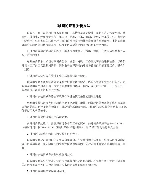
球阀的正确安装方法球阀是一种广泛使用的流体控制阀门,其特点是开关快捷、密封可靠、结构简单、重量轻、体积小、使用寿命长等。
在工业、建筑、化工、石油、制药、轻工等行业中都得到广泛应用。
球阀安装的正确性对于阀门的性能发挥和使用寿命具有重要影响。
本篇文章将详细介绍球阀的正确安装方法,以及不同类型的球阀应该注意的一些问题。
1.球阀在安装前必须进行检查,确认球阀的型号、规格、材质、工作压力等参数是否与工艺流程相符。
球阀的安装前,必须对球阀的型号、规格、材质、工作压力等参数进行检查,以确保球阀与工厂的工艺流程相匹配,避免由于选择错误的球阀导致阀门不能正常工作,影响生产过程。
2.球阀的安装要求在管道系统中与调节装置相配合。
球阀的安装要求与管道系统及其控制系统紧密配合,以确保管道系统的良好运行。
在管道系统的选型和设计中,应充分考虑球阀的特点,包括:阀门的工作压力、介质压力、温度范围、流量系数和密封性等。
3.球阀的安装要求在符合环境条件和场地使用条件的基础上进行。
球阀的安装也需要考虑当地的环境和场地使用条件。
例如球阀的安装位置应尽量靠近原有的管线,且便于操作和维护,减少漏气或泄漏问题。
球阀的安装应符合当地安全规范,保证使用人员的安全。
4.球阀的安装应遵循相关标准要求。
在球阀安装过程中,需要严格遵守相关标准的要求,如球阀安装应符合GB/T 12237 《钢制球阀》和GB/T 12238《铸铁球阀》等标准要求,以确保球阀的性能和安全性。
5.球阀的安装应注意阀门的安装方向和流向。
球阀的安装应注意阀门的安装方向和流向。
在安装过程中应根据工作流体的流向确定阀门的安装位置,防止因阀门的安装方向错误导致阀门无法正常工作或流体的冲击威力增强。
6.球阀的安装要求在安装时应监测力矩。
球阀的安装需要注意在安装时应对球阀的力矩进行检测。
在安装过程中针对不同类型的球阀需要采用不同的力矩检测方法来确保安装的质量和稳定性。
7.球阀的安装应提前保养和润滑。
球阀安装说明书一、阀门安装前检查:1检查阀门通道内是否有杂物;2检查密封面是否有损伤;3检查阀门是否正常;4确认阀门是否处于开启位置。
5应采用正确的方式吊装阀门,使阀门保持平衡。
6请勿将吊链系于手轮,齿轮箱或执行器上起吊。
7在吊装阀门期间应使端部保护盖保持在原位。
只有当阀门安装前,才可移去保护盖。
8在吊装时,请注意保护阀门端面及阀门配件不受损坏,否则将导致阀门受损。
9保证足够空间便于阀门的操作。
10球阀为90度回转操作阀,顺时针关,逆时针开。
对于手柄操作的阀门,应留有足够的空间来操作。
11安装前仔细核对阀门标志是否与使用要求相符。
12安装前应检查阀门通道和密封面,如有污垢附着,用清洁的软布擦去。
13安装前应检查手动装置是否灵活,有无卡阻现象。
14当阀门装到管线中时,紧固对角螺栓。
15不要在阀门安装好后再焊接管线法兰,焊接后不要立即安装阀门。
16电动阀门操作时禁止用手柄操作。
17不允许管线螺栓部分紧固。
18避免对法兰两端用力。
19阀门安装时应预留检修空间。
20阀门工作时,必须处于全开或全关位置。
不推荐将阀门部分开启作调节流量用。
21阀门的表面、阀杆等部位容易粘积灰尘、油污以及介质残渍,对阀门易产生磨损和腐蚀,应经常清扫。
二、管线测试系统1安装阀门的管线系统进行静压测试时,请遵循以下步骤以避免造成阀门内密封面和阀座密封的损害。
当向管线系统加入介质时,阀门应处于全开位置,这样可将管线中的碎屑通过球体通道冲刷出管线。
一旦管线清扫完毕并向系统中充满试验介质,球阀应置于中间位置(约离全开位15°的位置),这样试验介质即可流入阀腔。
这时阀门已做好试压准备。
将阀门转向全位或需要操作的位置。
2对于法兰连接的阀门,为保证垫片均匀受力起到良好的密封效果,螺栓紧固时应按对角紧固的方法进行操作。
三、对焊连接端的阀门焊接注意事项1如果在阀门安装时,球体必须保持关位,请将暴露在外的球体表面涂上油脂。
这样可以保护球体不被飞溅的焊渣损坏。
格罗夫公司B8球阀安装和维修指南M-004-E客户:订单号:B8 系列球阀1.安装1.1阀门搬动阀门的搬动应使用适当的吊耳。
搬动阀门应小心轻放。
搬动时不得抬手轮或阀杆。
阀门搬动应使用起重机小心吊起。
1.2阀门位置阀门安装时可以让任一端为上游。
阀门安装应便于操作和维修。
安装前应确认铭牌再次验明阀门。
阀门应妥善支撑并应与管线成一直线。
同时应考虑管线扩张而引起对阀门的压力。
应避免对阀体过高的压力。
1.3焊接说明阀门与管线如为焊接端连接,则焊接应采用适当的步骤。
如需焊后热处理,阀门必须配焊接短节。
在安装和焊接时,阀门应处于全开的位置。
暴露的球体部分应涂以黄油或其他粘接的产品,以防止球体被焊接火花损伤。
焊接后应对焊接处进行清理和检查。
如有必要,应进行修补。
1.4操作打开阀门应使阀杆逆时针旋转90度停止。
关闭阀门应使阀杆顺时针旋转90度停止。
注:格罗夫的标准产品是开/关两位阀门,为避免出现严重问题在任何情况下不应当作节流阀使用。
按照要求,球体必须总处于全开或全关的位置。
维修指导2.0 范围本维修指导所说明的只是B8球阀的现场维修。
超出本指导以外的维修应在Grove事先授权的维修站进行维修。
3.1 紧急密封脂性能B8球阀按设计在正常情况下不需加注密封脂。
当发现阀座有泄漏时,可以在阀门关闭后,注入密封脂临时性地密封阀门。
密封脂的注入应通过注脂管件注入,同时球体必须处于关闭位置。
对于埋地式阀门,应通过加长管注入。
3.2 建议的密封脂:Fuchs Renax SK2 : 操作温度-30度到+40度用于天然气。
Climax 340 : 操作温度-30度到+200度用于酸气Sealweld NS-70 : 操作温度-60度用于低温。
4.3 排放任何阀门总会在阀腔内积水或沉积其他的杂质。
这时阀门或许会出现如下的问题。
1)阀腔会结冰,使阀门无法动作。
2)杂质会阻止阀门全关闭,使阀门处于半开节流状态,这样可能损坏球体或阀座O形环。
全焊接球阀安装要求与维护一、全焊接球阀安装要求:1.安装位置选择:球阀应安装在易于操作和维护的位置,便于操作人员进行操作和维护。
2.阀门方向确定:在安装球阀时,应根据流体的流向确定阀门的安装方向,确保球阀在正常工作状态下提供最佳的加工能力。
3.禁止侧向力:球阀的安装过程中应避免产生过大的侧向力,以免影响球阀的正常操作。
4.弹簧压缩:球阀在安装时,应将手柄旋转到关闭位置,并将弹簧压缩到合适的位置,以防止出现弹簧松脱或失效的情况。
5.使用合适的密封材料:根据介质的性质选择合适的密封材料,以确保球阀的密封性能和安全性能。
6.弹簧标记:球阀的弹簧可以根据需要进行标记,以便维护人员在维护时能够正确安装弹簧。
7.阀门安装:首先将球阀放在要安装的管道上,然后用法兰将球阀固定在管道上,并确保不出现泄漏情况。
8.连接阀门和管道:使用合适的密封材料和正确的连接方法将球阀与管道连接起来,确保连接牢固。
二、全焊接球阀维护要求:1.周期性维护:定期对球阀进行维护,包括检查球阀的密封性能、操作性能和部件状况等,及时发现和处理问题。
2.清洁球阀:定期清洁球阀的内部和外部,包括球体、密封面、阀座等,以确保球阀的正常工作。
3.替换磨损部件:定期检查球阀的密封面和阀座状况,如果有磨损或损坏的情况,应及时更换相关部件,以确保球阀的密封性能。
4.润滑球阀:定期对球阀进行润滑,以减少摩擦和磨损,并确保球阀的正常运行。
5.全面检查:定期对球阀进行全面的检查,包括外观状况、操作机构、密封性能和阀门部件等,以确保球阀的完好性和可靠性。
6.维护记录:对球阀的每次维护都应做好记录,包括维护内容、时间和人员等,以便后续的维护参考。
总结:全焊接球阀的安装和维护要求相对较为严格,只有按照要求进行安装和维护,才能确保球阀的正常工作和使用寿命。
在安装过程中要注意阀门方向、禁止侧向力等,而在维护过程中要注重周期性维护、清洁和润滑,并定期对球阀进行全面检查和记录。
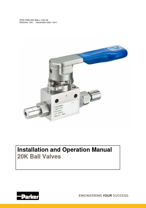
Installation and Operation Manual20K Ball ValvesParker HannifinParker Hannifin (IPDE)Riverside Road, Barnstaple, Devon, EX31 1NP United KingdomTelephone: (01271) 313131E-mail:*****************************.comIDENTIFICATION OF HAZARDSNEVER adjust valves under pressure.NEVER slacken or remove any valve parts under pressure.NEVER use any mechanical aids i.e. wrenches, extensions to operate handles.NEVER carry valves by the handle.NEVER obscure valve body marking.NEVER remove end connectors.INSTALLATIONWear suitable PPE before installation and follow appropriate site safety procedures.Before installation, ensure that all valves are in the closed position.Phastite: Assembly instructions can be found in Catalogue 4235-PH & BULLETIN 5909Cone and Thread: Assembly instructions and Torques can be found in Catalogue 02-0124SE MPI: Assembly instructions can be found in Catalogue 4234-MACare should be taken to ensure that the end connector (9) is firmly held by an appropriate spanner / wrench (size varies depending on size of valve) to prevent any movement when assembling or disassembling connections.(See Catalogue 4190-HH/20K for full product offering)HANDLING AND STORAGEHandlingDo not lift or carry by the operating handles, as this may cause damage.StorageThere is no specified shelf-life.Boxed products should be stored in a covered area, preferably indoors, and away from excessive moisture, heat, or airborne contaminants.The use of desiccant or corrosion inhibitors is not required during normal storage periods.Installation and Operation Manual 20K Ball ValvesOPERATIONBall Valve:To close: Operate the handle (6) until it is at 90° from the valve body centreline.To open: Operate the handle (6) until it is in line with the centreline of the body and reaches the mechanical stop (3).Movement is limited to 90° by a mechanical stop.Ball valves should always be fully open or fully closed. Do not leave in a mid-position.MAINTENANCEParker 20K Ball Valves are supplied ready for service at their rated design pressure and should not normally require adjustment.Gland adjustment becomes necessary when the valve is visibly leaking via the gland adjuster (11).20K Ball Valve Gland Adjustment.CAUTION: Adjustment of the gland must be carried out at zero pressure1. Fully open the valve by operating the handle (6) until it is in line with the centreline of thebody.2. Unscrew Grub Screw (5) on handle (6) and remove handle from stem.3. Unscrew Socket Head Cap Screw (3) from Tru-Loc Plate and remove Tru-Loc Mechanism(4).4. Tighten Gland Nut (11) to 45 Nm5. Re-fit Tru-Loc plates (4) and secure in position with Socket Head Cap Screw (3) to 7.9 Nm.6. Re-fit handle (6) onto stem and secure into position with Grub Screw (5) to 9 Nm.1. BODY2. VALVE CONNECTIONS3. M6 SOCKET HEAD CAP SCREW4. TRU-LOC LOCKING MECHANISM5. M8 GRUB SCREW6. HANDLE7. HANDLE SLEEVE8. PANEL MTG. HOLE 9. END CONNECTOR 10. BRACKET MOUNTING HOLES11. GLAND ADJUSTER*HANDLE SHOWN AS SECTIONAL VIEW FOR CLARITYInstallation and Operation Manual20K Ball ValvesFURTHER INFORMATIONBall valve maximum Cv Value is 1.56 (Dependant on fitting size).For Panel Mounting of the 20K Ball Valve please follow the below:20K Needle Valve Panel Mounting.1.Unscrew Grub Screw (5) on handle (6) and remove handle from stem.2.Unscrew Socket Head Cap Screw (3) from Tru-Loc Plate and remove Tru-Loc Mechanism(4).3.Position valve body in panel and fasten into position with an M6 Socket Head Cap Screw(See Bolt Length note below) using mounting hole (8).4.Re-fit Tru-Loc plates (4) and secure in position with M6 Socket Head Cap Screw (3) Length20mm to 7.9 Nm.5.Re-fit handle (6) on to stem and secure into position with Grub Screw (5) to 9 Nm.20K Ball ValvesWARNING - USER RESPONSIBILITYFAILURE OR IMPROPER SELECTION OR IMPROPER USE OF THE PRODUCTS DESCRIBED HEREIN OR RELATED ITEMS CAN CAUSE DEATH, PERSONAL INJURY AND PROPERTY DAMAGE. This document and other information from Parker Hannifin Corporation, its subsidiaries and authorized distributors provide product or system options for further investigation by users having technical expertise.The user, through its own analysis and testing, is solely responsible for making the final selection of the system and components and assuring that all performance, endurance, maintenance, safety and warning requirements of the application are met. The user must analyse all aspects of the application, follow applicable industry standards, and follow the information concerning the product in the current product catalogue and in any other materials provided from Parker or its subsidiaries or authorized distributors.To the extent that Parker or its subsidiaries or authorized distributors provide component or system options based upon data or specifications provided by the user, the user is responsible for determining that such data and specifications are suitable and sufficient for all applications and reasonably foreseeable uses of the components or systems.。
Contents1.SCOPE (2)2.INSTALLATION (2)3.VALVE OPERATION (3)4.DISASSEMBLY (3)5.ASSEMBLY (4)6.REPAIR KITS (4)1.SCOPE1.1.CAUTION1.1.1.For your safety, read this manual before installation or service.1.1.2.Before installing or servicing, please ensure the line pressure has been relieved and any hazardous fluids have beendrained or purged from the system.1.1.3.Ensure that all Lockout and Tagout procedures for the system have been properly implemented.E1.2.1.Maximum results and long life of valves can be maintained under normal working conditions and according withpressure/ temperature ratings and corrosion data chart.2.INSTALLATION2.1.GENERAL INFORMATION FOR INSTALLATION2.1.1.The valve can be installed in any position on the pipeline.2.1.2.Before installation of the valve, the pipe must be flushed clean of dirt, burrs, and welding residue, or the seats and ballsurface will be damaged. The pipe must be free from tension and in proper alignment. Check to ensure that allconnections are free from defects.2.2.INSTALLATION OF THREADED VALVESe conventional sealant, such as hemp core, Teflon, etc. on threads. Apply wrench only on the hexagon of the valveends. Tightening by using the valve body or lever can seriously damage the valve. In some applications, screwedvalves are back welded on site. These valves must be treated as per instructions for the weld end valves before backwelding.2.3.INSTALLATION OF WELDED ENDS2.3.1.Tack weld the valves on the pipe in four points on both end caps.2.3.2.With the valve in the open position, (lever to be parallel to the axis of the pipe), remove all the body bolts except one.Loosen the nut on the remaining bolt. Swing the body outside the pipe. Finish welding both end caps on the pipe.2.3.3.When cooled down, clean both end caps and body surface.2.3.4.Swing the body back in position and replace the body bolts. Tighten all nuts slightly. This operation is very importantto keep the body and end caps perfectly parallel, thus preventing distortion of end caps. Tighten body bolts evenly (seesection 5.5). Make sure that maximum tightening torque is observed. Check proper operation of the valve.3.VALVE OPERATION3.1. MANUAL3.1.1.HANDLE3.1.1.1.To OPEN the valve, turn the handle counterclockwise until the handle is parallel with the pipeline and the handlehas contacted the handle stop.3.1.1.2.To CLOSE the valve, turn the handle clockwise until the handle is perpendicular with the pipeline and the handlehas contacted the handle stop.3.1.1.3.A handle lock is incorporated into the handle. To use, slide the lock into the mounting pad, in the full open orfull closed position. Insert an appropriate size lock or hasp into the handle. If it can be performed safely, try toturn the handle to ensure that the valve has been locked properly.3.1.2.GEAR3.1.2.1.To OPEN the valve, turn the handle wheel counterclockwise. The indicator will be pointing to the open positionand stop rotating when fully opened. The flow can be adjusted by stopping the indicator anywhere between openand close.3.1.2.2.To CLOSE the valve, turn the handle wheel clockwise. The indicator will be pointing to the close position andthe hand wheel will stop rotating when fully closed. The flow can be adjusted by stopping the indicatoranywhere between open and close.3.2.AUTOMATED3.2.1.A-T Controls 55 Series Ball Valves can be mounted with quarter turn actuators. Valves with actuators shall be checkedfor proper valve stem alignment. Angular or linear misalignment may result in high operational torque and unnecessarywear on the valve stem. See the actuator IOM for information on operating the actuator.4.DISASSEMBLYWARNINGCAUTION, FLUIDS CAN BE TRAPPED IN THE BODY OF THE VALVE, POSSIBLY UNDER HIGH PRESSURE. FOR YOUR SAFETY, IT IS IMPORTANT THAT PRECAUTIONS ARE TAKEN BEFORE REMOVAL OF THE VALVE FROM THE LINE OR ANY DISASSEMBLY.4.1.Remove actuator or gear if equipped.4.2.Care should be taken to not damage the surface finish of the valve components,4.3.Remove the ends (2) from the body (1) by removing the body bolts (14), body nuts (17), and lock washers (18).4.4.Remove the seats (8) and body gaskets (13) from both sides of the body (1). Once removed, with the valve in the fullyclosed position, the ball (3) should slide freely out of the body (1).4.5.If equipped, remove the handle nut (21), handle (7), and the handle stop assembly (15).4.6.While holding the stem (4) stationary, remove the packing nut (5). Once removed, the locking saddle (12), Bellevillewashers (6), and the packing bushing (9) should be free to remove.4.7.While holding the bottom of the stem (4), push the stem (4) through the inside of the valve body (1).4.8. Remove the packing set (10) and the thrust washer (11).4.9.Inspect all components for damage and, if necessary, clean or replace.5.ASSEMBLY5.1.Care should be taken to not damage the surface finish of the valve components.5.2.Place thrust washer (11) on the stem (4) and install it by going through the body (1). Insert V-style packing set (10) overstem (4) with the V pointing away from the valve (see Bill of Materials for correct orientation).5.3.Install the packing gland (10), Belleville washers (6), the locking saddle (12), and the packing nut (5). While holding thestem (4), tighten the packing nut (5) to the torque listed in the Fastener Torque Chart. Tighten further if needed in order to be able to place the locking saddle (12) over the packing nut (5).5.4.Ensure the stem (4) is in the closed position with the body tang parallel with the flow of the valve. Insert a seat (8) and bodygasket (13) in one side of the body (1). Carefully slide the ball (3) into the body (1) and insert the other seat (8) and body gasket (13).5.5.Assemble ends (2) onto body (1). Insert all body bolts (14), body nuts (17) and lock washers (18) into valve and tighten tofinger tight, making sure that the ends (2) are flat against the body (1). Tighten all body bolts (on both sides for 2-1/2” thru 4”) from the nut (17) to 50% of the max bolt torque in a star pattern. Check each body bolt (14) torque and tighten a final time to the max torque of the body bolts. It is acceptable for the torque to relax slightly over time due to relaxation of the polymer components, but the valve will still seal properly. If leakage is detected, repeat the steps for tightening the body bolts (14).5.6.If required, assemble the locking device (20), handle stop (15), handle (7), and the handle nut (21).6.REPAIR KITSRepair kits are available to replace all soft goods. See Bill of Materials for components that are included in the repair kits.7.BILL OF MATERIALSA-T Controls product, when properly selected, is designed to perform its intended function safely during its useful life. However, the purchaser or user of A-T Controls products should be aware that A-T Controls products might be used in numerous applications under a wide variety of industrial service conditions. Although A-T Controls can provide general guidelines, it cannot provide specific data and warnings for all possible applications.The purchaser / user must therefore assume the ultimate responsibility for the proper sizing and selection, installation, operation, and maintenance of A-T Controls products. The user should read and understand the installation operation maintenance (IOM) instructions included with the product and train its employees and contractors in the safe use of A-T Controls products in connection with the specific application.While the information and specifications contained in this literature are believed to be accurate, they are supplied for informative purposes only.Because A-T Controls is continually improving and upgrading its product design, the specifications, dimensions and information contained in this literature are subject to change without notice. Should any question arise concerning these specifications, the purchaser/user should contact A-T Controls.For product specifications go to https:///Downloads/。
吉林敦化抽水蓄能电站机电安装工程(合同编号:SGXYDH-JH-DGCSG[2016]22号)1号、2号机组球阀安装方案吉林敦化抽水蓄能电站机电安装1416闽一电建联营体项目部2019年5月批准:审定:审核:复核:编制:目录1. 工程概述 (1)1.1 主要技术特性 (1)1.2进水阀主要安装工作量 (2)2. 编制依据 (2)2.1 合同文件 (2)2.2 厂家资料及相关资料 (2)2.3 规范要求 (2)3. 施工计划 (2)3.1 计划投入设备(或工器具) (2)3.2 计划投入人员 (3)4. 施工流程图 (4)5. 施工工艺措施 (4)5.1 施工准备 (4)5.2 中心线和基准点布置 (5)5.3 球阀及接力器基础安装 (5)5.4 球阀吊装 (7)5.5 伸缩节装配吊装 (9)5.6 球阀上游连接管安装 (10)5.7 球阀上游连接管焊接 (10)5.8 活套法兰安装 (10)5.9 接力器安装 (11)5.10 系统管路安装 (13)5.11 球阀调试 (14)6. 成品保护措施 (16)7. 质量保证措施 (16)7.1 球阀安装 (16)7.2 球阀上游连接管的焊接质量控制 (18)8. 安全生产和文明施工措施 (19)8.1 施工安全控制措施 (19)8.2 现场文明施工管理 (20)9. 本方案执行的强制性条文 (21)附件1:球阀安装风险管控表 (24)附件2:水电工程安全施工作业票 (26)1号、2号机组球阀安装方案1. 工程概述本电站的进水阀为卧轴双面密封球阀,设一道检修密封(上游侧)和一道工作密封(下游侧),其中上游侧检修密封设有防腐机械锁锭装置,下游工作密封由进水阀控制系统自动控制。
采用双杠双向液压接力器开启、关闭球阀。
球阀为整体结构,每台球阀配置1套油压装置。
图1-1 进水阀示意图1.1 主要技术特性进水阀形式:球型阀,卧轴;进水阀公称直径:2.1m;额定工作油压:6.3MPa;进水阀设计压力:1160m;进水阀试验压力:1740m;压力油罐容积:13m3;集油箱容积:11 m3;漏油箱容积:0.25m3;进水阀所有部件总重:210t。
气动球阀安装说明
气动球阀在安装前:
1、保证气动球阀安装位置管线在同轴位置上,管线上两片法兰应保持平行,确认管线能够承受气动球阀自身重量,如果发现管线不能承受气动球阀重量,则在安装前为管线配备相应的支撑。
2、确认管线内是否有杂质、焊渣等,必须要把管线内吹扫干净。
3、核对气动球阀铭牌,并进行全开全闭数次操作,确认阀门能够正常工作,再全面检查一次阀门的各个细节,保证阀门完好无损。
4、除去两端的保护盖,检查阀体内是否干净,清洗阀体内腔,由于气动球阀的密封面是球形状,即使微小的杂物也可能造成密封面的损伤。
气动球阀的安装:
1、气动球阀法兰与管线法兰间按管路设计要求装上密封垫。
2、法兰上的螺栓需对称、逐次、均匀拧紧。
3、球阀采取气动执行器时,按说明书完成气源的安装。
4、气动球阀的任何一段都可安装在上游端,手柄气动管路球阀可以安装在管线的任何位置,如果配置电-气动执行器的球阀,则必须垂直安装,阀门进出口处在水平位置上。
气动球阀安装后的检查:
1、安装完毕后,启动气动球阀开、关数次,应该动作灵活,受力均匀,气动球阀工作正常。
2、根据管道压力设计要求,通压后检测气动球阀与管道法兰结合面的密封性能。
球阀的安装及维修介绍球阀是一种常见的阀门,一般用于对流体介质的开关控制。
球阀采用球体作为开启和关闭的断口,具有结构紧凑、密封性好、操作轻便等优点,被广泛应用于工业、建筑、水处理等领域。
在使用球阀之前,需要进行正确的安装和维修,以确保阀门的正常运行和使用寿命。
本文将详细介绍球阀的安装和维修方法,供读者参考。
球阀的安装球阀的安装应根据阀门结构和使用环境进行合理安装,具体步骤如下:1. 准备工作首先检查球阀的主要部件是否符合要求,并确认相关技术参数是否符合实际要求。
然后清理和检查管道,并进行测量,确认管道尺寸和安装位置。
2. 安装阀门将球阀放置在正确的安装位置,根据阀门的连接方式和管道的布局,采用正确的连接方式将球阀与管道相连接,然后固定好螺钉,注意阀门的紧固度。
安装结束后,应开启球阀进行试运行,确认阀门是否正常运转。
3. 连接操作机构球阀安装完成后,需要根据需要连接操作机构,如手动操作、电动操作、气动操作等。
连接操作机构时,应根据球阀操作方式和相关参数进行正确的选型和连接。
球阀的维修球阀需要定期进行维护和保养,以确保其正常运行和安全使用。
球阀的维修应根据具体情况进行,常见小型球阀的维修步骤大致如下:1. 拆卸阀门将球阀拆卸下来,然后进行拆解。
在进行拆卸之前,应先将管道内的介质排完,并将球阀再次打开,以释放内部压力。
2. 拆卸球体拆卸球体时,应注意不要划伤或损坏密封面。
如果球体密封面损坏,则需要更换新的密封面。
3. 拆卸密封座拆卸密封座时应注意不要弯曲和损坏。
同时,应清理密封座和球体之间的污垢和沉积物,使其表面光滑。
4. 检查和更换密封件球阀需要更换的密封件包括密封座和球体密封面。
在更换密封件时应注意选用合适的材料,同时按照厂家提供的技术参数进行更换。
5. 安装組裝在更换密封件完成后,应将球阀进行安装组装。
安装时应格外注意阀门的连接方式、螺栓的紧固度和操作机构的连接状态。
结语球阀是一种常用的阀门,在工业、建筑、水处理等领域都发挥着重要作用。
Contents1SCOPE (2)2INSTALLATION (2)3VALVE OPERATION (3)4DISASSEMBLY (4)5ASSEMBLY (4)6REPAIR KITS (5)7BILL OF MATERIALS (6)1SCOPE1.1CAUTION1.1.1For your safety, read this manual before installation or servicing.1.1.2Before installing or servicing, please ensure the line pressure has been relieved and any hazardous fluids havebeen drained or purged from the system.1.1.3Ensure that all Lockout and Tagout procedures for the system have been properly implemented.1.2USE1.2.1A-T Controls H78-Series Ball Valve are available in Hygienic Ferrule Ends (½” & ¾” Type A, 1”-4” Type B) orExtended Tube Butt Weld Ends.1.2.2Maximum results and optimum valve life can be maintained under normal service conditions and in accordancewith pressure/temperature ratings and corrosion data charts.2INSTALLATION2.2A-T Controls H78-Series Ball Valves are bi-directional and can be installed with the flow in either direction. Thevalve can be mounted in any position so that the handle, gear, or actuator has proper clearance, allows foroptimal drainage, can be easily accessed, and the open/close indicator can be viewed. If the gear is equipped witha chain wheel, the valve shall be mounted in a way so that the chain does not come in contact with the valve orpipeline.2.3Before installation of the valves, the pipe must be flushed clean of dirt, burrs, and welding residues. Failure to doso can cause the seats, sealing surfaces, and internal polish to be damaged.2.4The pipe must be free from tension and in proper alignment.2.5Before installation of the valves, check to ensure that all connections are free from defects.2.6Be sure to consult with supplier of your clamps and gaskets to be used on the hygienic ends for the propermaterial, pressure rating, and clamp torque for your process. Over torqueing clamps may result in damage to the ferrule end.2.7Disassembly of the valve is not necessary for tube end valves. However, caution should be taken to ensure thatthe heat source does not come in contact with the sealing components of the valve in excess of the sealingcomponent temperature limitation.3VALVE OPERATION3.1MANUAL3.1.1HandleTo open the valve, pull up on the handle lock and turn the handle counter-clockwise until the handle isparallel with the pipeline and the handle has contacted the handle stop.To close the valve, pull up on the handle lock and turn the handle clockwise until the handle isperpendicular with the pipeline and the handle has contact the handle stop.A handle lock is incorporated into the handle. To use slide the lock into the mounting pad, in the fullopen or full closed position. Insert an appropriate size lock or hasp into the hole in the handle. If it canbe performed safely, try to turn to ensure that the valve has been locked properly.3.1.2GearTo OPEN the valve; turn the hand wheel counter-clockwise. The indicator will be pointing to the openposition and stop rotating when fully opened. The flow can be adjusted by stopping the indicatoranywhere between open and close.To CLOSE the valve; turn the hand wheel clockwise. The indicator will be pointing to the close positionand the hand wheel will stop rotating when fully closed. The flow can be adjusted by stopping theindicator anywhere between open and close.3.2AUTOMATEDA-T Controls H78-Series High Purity Ball Valves can be mounted with quarter turn actuators. Valves withactuators shall be checked for proper valve stem alignment. Angular or linear misalignments may resultin high operational torque and unnecessary wear on the valve stem. See the actuator IOM forinformation on operating the actuator.4DISASSEMBLYWARNINGCAUTION, FLUIDS CAN BE TRAPPED IN THE BODY OF THE VALVE, POSSIBILY UNDER HIGH PRESSURE. FOR YOUR SAFETY, IT IS IMPORTANT THAT PRECAUTIONS ARE TAKEN BEFORE REMOVAL OF THE VALVE FROM THE LINE OR ANY DISASSEMBLY.4.1Remove actuator or gear if equipped.4.2Care should be taken to not damage the surface finish of the valve components.4.3Remove the ends (2/3) from the body by removing the body bolts (8) and body nuts (9).4.4Remove the seat (5) and body gasket (6) from both sides of the body (1). Once removed, with the valve in the fullyclosed position, the ball (4) should slide freely out of the body (1).4.5If equipped, remove the handle nut (14), handle (16), and handle stop assembly (17).4.6Using a small screw driver, bend the locking saddle (15) down so that the packing nut (14) is able to turn freely. 4.7While holding the stem (7) stationary, remove the packing nut (14). Once removed, the locking saddle (15),conical spring washers (13) and packing gland (12) should be free to remove.4.8While holding the bottom of the stem (7), push the stem (7) through the inside of the valve body (1).4.9Remove the packing set (11) and thrust bearing (10).4.10Inspect all components for damage and if necessary clean or replace.5ASSEMBLY5.1Care should be taken to not damage the surface finish of the valve components.5.2Place thrust bearing (10) on the stem (7) and install it by going through the body (1). Insert V-Style packing set (11)over stem (7) with the V pointing away from the valve (see Bill of Materials for correct orientation).5.3Install the packing gland (12), the conical spring washers (13), locking saddle (15), and packing nut (13). Whileholding the stem (7), tighten the packing nut (14) to the torque listed in the Fastener Torque Chart. Tightenfurther if needed in order to be able to bend the locking saddle (15) over a flat side of the packing nut (14).5.4Ensure that the stem (7) is in the closed position with the bottom tang parallel with the flow of the valve. Insert aseat (5) and body gasket (6) in one side of the body (1). Carefully slide the ball (4) into body (1) and insert the other seat (5) and body gasket (6).5.5Assemble ends (2/3) onto body (1). Insert all body bolts (8) and nuts (9) into valve and tighten to finger tight,making sure that the ends (2/3) are flat against the body (1). Tighten all bolts (8) (on both sides for valves 2-1/2”- 4”) from the nut (9) side (if equipped) in a star pattern to 50% of the final torque shown in the Fastener Torque Chart. Using the handle (16) or an adjustable wrench, cycle the valve 3 times. Tighten all of the body bolts (8) to the final torque in a star pattern. Cycle the valve 3 times again. Check each body bolt torque (8) and tighten if needed a final time. It is acceptable for the torque to relax slightly over time due to relaxation of the polymer components, but the valve will still seal properly. If leakage is detected, repeat the steps for tightening the body bolts.5.6If required, assemble the handle stop assembly (17), handle (16), and handle nut (14).Fastener Torque ChartValve SizeBody Bolt Torque (in *lbs) Packing NutTorque (in*lbs) 50% of Final Torque Final Torque1/2" 68 135 783/4" 68 135 781" 73 145 1221-1/2" 195 390 2002" 283 565 2002-1/2" 413 825 2003" 455 910 2004" 673 1345 2176REPAIR KITSRepair kits are available to replace all soft goods. See Bill of Materials for components that are included in the repair kits.7BILL OF MATERIALSITEM NO. PART NAME REPAIR KIT QTY. MATERIAL1 BODY 1 ASTM A351-CF3M2 END CONNECTION 2 ASTM A351-CF3M3 END CONNECTION 2 ASTM A351-CF3M4 BALL 1 ASTM A351-CF3M5 SEAT X 2 TFM TM-1600 FDA6 BODY GASKET X 2 TFM TM-1600 FDA7 STEM 1 ASTM A276-3168 BODY BOLT # ASTM A193 GR B89 BODY NUT & ASTM A194 GR 810 THRUST BEARING X 1 TFM TM-1600 FDA11 PACKING SET X 1 TFM TM-1600 FDA12 PACKING GLAND 1 AISI-30413 CONICAL SPRING WASHER 2 AISI-30114 PACKING / HANDLE NUT 2 AISI-30415 LOCKING SADDLE 1 AISI-30416 HANDLE WITH LOCK 1 AISI-30417 HANDLE STOP ASSEMBLY 1 AISI-304# FOR 1/2"-1-1/2" - 4 PCS; FOR 2"-2-1/2" - 8 PCS; FOR 3" - 12 PCS, FOR 4" -16 PCS& FOR 1/2"-1-1/2" - 4 PCS; FOR 2"-4" - 0 PCSA-T Controls product, when properly selected, is designed to perform its intended function safely during its useful life. However, the purchaser or user of A-T Controls products should be aware that A-T Controls products might be used in numerous applications under a wide variety of industrial service conditions. Although A-T Controls can provide general guidelines, it cannot provide specific data and warnings for all possible applications. The purchaser / user must therefore assume the ultimate responsibility for the proper sizing and selection, installation, operation, and maintenance of A-T Controls products. The user should read and understand the installation operation maintenance (IOM) instructions included with the product and train its employees and contractors in the safe use of A-T Controls products in connection with the specific application.While the information and specifications contained in this literature are believed to be accurate, they are supplied for informative purposes only. Because A-T Controls is continually improving and upgrading its product design, the specifications, dimensions and information contained in this literature are subject to change without notice. Should any question arise concerning these specifications, the purchaser/user should contact A-T Controls.For product specifications go to https:///Downloads/A-T Controls, Inc. • 9955 International Boulevard, Cincinnati, OH 45246 • Phone: (513) 530-5175 • Fax: (513) 247-5462 • 。
Contents1SCOPE (2)2INSTALLATION (2)3VALVE OPERATION (3)4DISASSEMBLY (4)5ASSEMBLY (4)6REPAIR KITS (5)7BILL OF MATERIALS (6)1SCOPE1.1CAUTION1.1.1For your safety, read this manual before installation or servicing.1.1.2Before installing or servicing, please ensure the line pressure has been relieved and any hazardous fluids havebeen drained or purged from the system.1.1.3Ensure that all Lockout and Tagout procedures for the system have been properly implemented.1.2USE1.2.1A-T Controls 77-Series Ball Valve are available in Hygienic Ferrule Ends (½” & ¾” Type A, 1”-4” Type B) orExtended Tube Butt Weld Ends.1.2.2Maximum results and optimum valve life can be maintained under normal service conditions and in accordancewith pressure/temperature ratings and corrosion data charts.2INSTALLATION2.2A-T Controls 77-Series Ball Valves are bi-directional and can be installed with the flow in either direction. Thevalve can be mounted in any position so that the handle, gear, or actuator has proper clearance, allows foroptimal drainage, can be easily accessed, and the open/close indicator can be viewed. If the gear is equipped witha chain wheel, the valve shall be mounted in a way so that the chain does not come in contact with the valve orpipeline.2.3Before installation of the valves, the pipe must be flushed clean of dirt, burrs, and welding residues. Failure to doso can cause the seats, sealing surfaces, and internal polish to be damaged.2.4The pipe must be free from tension and in proper alignment.2.5Before installation of the valves, check to ensure that all connections are free from defects.2.6Be sure to consult with supplier of your clamps and gaskets to be used on the hygienic ends for the propermaterial, pressure rating, and clamp torque for your process. Over torqueing clamps may result in damage to the ferrule end.2.7Disassembly of the valve is not necessary for tube end valves. However, caution should be taken to ensure thatthe heat source does not come in contact with the sealing components of the valve in excess of the sealingcomponent temperature limitation.3VALVE OPERATION3.1MANUAL3.1.1HandleTo open the valve, turn the handle counter-clockwise until the handle is parallel with the pipeline andthe handle has contacted the handle stop.To close the valve, turn the handle clockwise until the handle is perpendicular with the pipeline and thehandle has contact the handle stop.A handle lock is incorporated into the handle. To use slide the lock into the mounting pad, in the fullopen or full closed position. Insert an appropriate size lock or hasp into the hole in the handle. If it canbe performed safely, try to turn to ensure that the valve has been locked properly.3.1.2GearTo OPEN the valve; turn the hand wheel counter-clockwise. The indicator will be pointing to the openposition and stop rotating when fully opened. The flow can be adjusted by stopping the indicatoranywhere between open and close.To CLOSE the valve; turn the hand wheel clockwise. The indicator will be pointing to the close positionand the hand wheel will stop rotating when fully closed. The flow can be adjusted by stopping theindicator anywhere between open and close.3.2AUTOMATEDA-T Controls 77-Series Ball Valves can be mounted with quarter turn actuators. Valves with actuatorsshall be checked for proper valve stem alignment. Angular or linear misalignments may result in highoperational torque and unnecessary wear on the valve stem. See the actuator IOM for information onoperating the actuator.4DISASSEMBLYWARNINGCAUTION, FLUIDS CAN BE TRAPPED IN THE BODY OF THE VALVE, POSSIBILY UNDER HIGH PRESSURE. FOR YOUR SAFETY, IT IS IMPORTANT THAT PRECAUTIONS ARE TAKEN BEFORE REMOVAL OF THE VALVE FROM THE LINE OR ANY DISASSEMBLY.4.1Remove actuator or gear if equipped.4.2Care should be taken to not damage the surface finish of the valve components.4.3Remove the ends (2) from the body by removing the body bolts (18) and body nuts (19).4.4Remove the seat (4) and body gasket (5) from both sides of the body (1). Once removed, with the valve in the fullyclosed position, the ball (3) should slide freely out of the body (1).4.5If equipped, remove the handle nut (13), handle (15), and handle stop assembly (22).4.6While holding the stem (7) stationary, remove the packing nut (13). Once removed, the locking saddle (12),Belleville washers (11) and packing bushing (10) should be free to remove.4.7While holding the bottom of the stem (7), push the stem (7) through the inside of the valve body (1).4.8Remove the packing set (8) and stem seal (6).4.9Inspect all components for damage and if necessary clean or replace.5ASSEMBLY5.1Care should be taken to not damage the surface finish of the valve components.5.2Place stem seal (6) on the stem (7) and install it by going through the body (1). Insert V-Style packing set (8) overstem (7) with the V pointing away from the valve (see Bill of Materials for correct orientation).5.3Install the packing gland (10), the Belleville washers (11), locking saddle (12), and packing nut (13). While holdingthe stem (7), tighten the packing nut (13) to the torque listed in the Fastener Torque Chart. Tighten further ifneeded in order to be able to bend the locking saddle (12) over a flat side of the packing nut (13).5.4Ensure that the stem (7) is in the closed position with the bottom tang parallel with the flow of the valve. Insert aseat (4) and body gasket (5) in one side of the body (1). Carefully slide the ball (3) into body (1) and insert the other seat (4) and body gasket (5).5.5Assemble ends (2) onto body (1). Insert all body bolts (18) and nuts (19) into valve and tighten to finger tight,making sure that the ends (2) are flat against the body (1). Tighten all bolts (18) (on both sides for valves 2-1/2”- 4”) from the nut (19) side (if equipped) in a star pattern to 50% of the final torque shown in the Fastener Torque Chart. Using the handle (15) or an adjustable wrench, cycle the valve 3 times. Tighten all of the body bolts (18) to the final torque in a star pattern. Cycle the valve 3 times again. Check each body bolt torque (18) and tighten if needed a final time. It is acceptable for the torque to relax slightly over time due to relaxation of the polymer components, but the valve will still seal properly. If leakage is detected, repeat the steps for tightening the body bolts.5.6If required, assemble the handle stop assembly (16), handle (15), and handle nut (13).Valve SizeTorque of Body Bolts (In-lbs.) Torque of Stem Nut(In-lbs.) 50% of Final Torque Final Torque1/2" 56 113 783/4" 61 122 781" 69 139 1221-1/2" 156 312 1652" 217 434 1652-1/2" 347 694 1913" 390 781 1914" 390 781 2176REPAIR KITSRepair kits are available to replace all soft goods. See Bill of Materials for components that are included in the repair kits.7BILL OF MATERIALSA-T Controls product, when properly selected, is designed to perform its intended function safely during its useful life. However, the purchaser or user of A-T Controls products should be aware that A-T Controls products might be used in numerous applications under a wide variety of industrial service conditions. Although A-T Controls can provide general guidelines, it cannot provide specific data and warnings for all possible applications. The purchaser / user must therefore assume the ultimate responsibility for the proper sizing and selection, installation, operation, and maintenance of A-T Controls products. The user should read and understand the installation operation maintenance (IOM) instructions included with the product and train its employees and contractors in the safe use of A-T Controls products in connection with the specific application.While the information and specifications contained in this literature are believed to be accurate, they are supplied for informative purposes only. Because A-T Controls is continually improving and upgrading its product design, the specifications, dimensions and information contained in this literature are subject to change without notice. Should any question arise concerning these specifications, the purchaser/user should contact A-T Controls.For product specifications go to https:///Downloads/A-T Controls, Inc. • 9955 International Boulevard, Cincinnati, OH 45246 • Phone: (513) 530-5175 • Fax: (513) 247-5462 • 。
球阀安装、使用与维护保养标准手册
一、目的
为加强对公司内常用球阀的安装、使用与维护保养,保证球阀的长周期正常使用,特制订本标准操作手册。
二、适用范围
公司内车间员工。
三、术语解释
球阀:球阀的启闭件是个球体,球体绕阀体中心线作旋转来达到开启、关闭的一种阀门,在管路中主要用来做切断、分配和改变介质的流动方向,它只需要用旋转90度的操作和很小的转动力矩就能关闭严密;适用于低压、小口径管道上用于截断水流和改变水流的分配或需快速启闭的场所。
四、基本流程
;
六、
工作指导
1、球阀安装前准备
1)安装前,确保前后管道同轴无扭曲。
如果是法兰连接,两法兰密封面必须平行。
当管道不能承受球阀的重量时,应在管道下部配有足以支撑管道和阀体的支撑。
球阀安装前准备
球阀的安装与使用
球阀的维护保养 球阀的维修
法兰
阀杆
球体
)
阀体
锁定装置
前后管道同轴,法
兰密封面平行
管道下部配有足以支撑
管道和阀体的支撑2)必须把球阀前后的管线吹扫干净,清除管道内部的油污等一切杂物。
用抹布清除密封
面上的杂物
3)拆除球阀两端连接法兰上的保护件。
>
在不损伤密封面的
情况下拆除保护件
4)检查阀孔清除可能有的污物,然后清洗阀孔,但在安装前要保证水分已被完全干燥,污物全部都被清除,阀座与球之间即使仅有微小颗粒的异物也可能
会损伤阀座密封面。
用抹布清除球阀内
部杂物,把水吹干。
5)核对球阀的标志和参数,检查球阀是否完好无损,将球阀全开全闭数次以保证其工作正常。
核对球阀的标志和参
数是否与管线适应
2、球阀的安装与使用
1)把球阀装上管线,不能用执行机构作为起重的吊装点,避免造成执行机构及附件的变形或损坏。
、
一人用手托住球阀,另
一人安装螺栓2)阀法兰与管线法兰间按管路设计要求装上密封垫。
3)法兰上的螺栓需对称、逐次、均匀拧紧,并抹上黄油保养。
4)对管道与球阀间的法兰结合面进行密封性能检查。
[
5)开启、关闭球阀数次,灵活无滞涩,其工作正常。
安装缠绕好的垫片并与密封面对齐
螺栓对角安装,保证螺母满冒
螺栓拧紧,并抹上黄油保养
观察密封面与垫片对齐,无泄漏
6)安装完成后管道试压,观察法兰处无泄漏。
3、球阀的维护保养
1)阀门只做开关使用,不宜做调节使用;特别不允许在超越温度、压力界线和频繁交变压力工况条件下使用,高温时允许周期性拧紧螺栓以防泄漏,尽力减少热梯度。
2)运行中的阀门要每天检查和维护,严防锈蚀卡阻,要始终保持设备处于完好状态。
,
3)填料涵处外漏,检查填料是否压紧。
如用软质填料加注密封方式时,需
再加注软质填料至不漏。
4)法兰处外漏,重新均匀拧紧螺栓一直不漏。
5)密封面内漏,检查是否关到位,密封面上是否有异物,在允许情况下打开阀门再关上看是否漏。
6)阀门检修时应重新清洗零件,清除异物,污渣和锈斑。
更换损坏的填料,垫片,修正密封面。
经检修、压力试验合格后方可再次投入使用。
4、球阀的维修
1)必须保证球阀上、下游管道确定已经卸除压力,才能进行拆卸维修操作。
2)拆卸及再装配时必须小心谨慎,防止损伤零件和密封面,尤其是非金属零件,取出O 型密封圈时一定要使用专用的工具(尖锥、弯锥、曲锥、装配钩、镊子等)。
3)如果是法兰连接,重新装配时法兰上的螺栓必须对称、逐步、均匀地拧紧。
不可用力过轻,连接不严密,也不可用力过猛,以防脱丝。
阀门关闭
阀杆顶部沟槽与管线平行阀门开启
4)清洗剂应与球阀中的橡胶件、塑料件、金属件及工作介质(例如燃气)等均相容。
工作介质为燃气时,可用汽油清洗金属零件。
非金属零件可用纯净水或酒精进行清洗。
5)分解下来的单个零件可以用浸洗方式清洗。
尚留有未分解下来的非金属件的金属件可采用干净的细洁的浸渍有清洗剂的绸布(为避免纤维脱落粘附在零件上)擦洗。
清洗时须去除一切粘附在壁面上的油脂、污垢、积胶、灰尘等。
6)非金属零件清洗后应立即从清洗剂中取出,不得长时间浸泡。
7)清洗后需待被洗壁面清洗剂挥发后(可用未浸清洗剂的绸布擦)进行装配,但不得长时间搁置,否则会生锈、被灰尘污染。
再重新装备前必须保证其干燥无污物。