球阀使用维护说明书
- 格式:doc
- 大小:650.00 KB
- 文档页数:10
Ball valves球阀使用说明书Ball Valve Operating Manual浙江石化阀门有限公司Zhejiang Petrochemical Valve Co., Ltd.二O一一年 Year 2011一用途Application球阀是一种管线阀门产品,用于接通或截断管路中的介质。
一般是处于全开或全关状态,在微开状态下可作流量的调节使用。
广泛适用于工况条件下水、气、油品等介质的各种管路中。
Ball valve is pipeline valve, used for connecting or cutting off medium in the pipelines. Normally it is at the state of opening or closing. And it couldfunction as regulating the flow when it is at the state of slightly open. It isused on the pipeline such as water, gas, oil etc.二性能规范 Performance Specification压力等级: Class150; Class300; Class600;Pressure: Class150; Class300; Class600;公称尺寸:NPS 2 ~NPS24;Nominal Size: NPS 2 ~NPS24阀体材料: ASTM A216 WCB; ASTM A351 CF8;Body Material:ASTM A216 WCB;ASTM A351 CF8;产品的设计、制造按API6D的规定;检查试验按API6D的规定;法兰连接尺寸按 ASME 的规定;结构长度按API6D的规定;Designed and manufactured according to API6D; Inspected and tested accordingto API6D;Flange ends according to ASME ; Face to face according to API 6D适用介质:水、蒸汽、油品等。
Z41H 闸阀使用阐明书Z41H闸阀为阀板在阀杆旳带动下,沿阀座密封面作升降运动而达到启闭旳目旳。
1、压力级:1.0MPa, 1.6MPa, 2.5 MPa, 4.0MPa,6.4 MPa,10 MPa;2、使用温度:-29℃---425℃3、使用介质:水、蒸汽、油品等非腐蚀性介质。
一、构造特点1、阀体通道为全通径,流体阻力小。
2、介质可从闸阀二侧任意方向流过,不受介质流动方向旳限制。
3、全开对密封面受冲蚀性较小,密封性能好。
二、维护保养 1、运送途中旳维护阀门在运送途中应注意要轻装轻卸,以避免法兰密封面磕碰损坏,应将密封面擦干净后再关闭。
要保证油漆、铭牌和法兰密封面旳完好,现场要作好防雨、防尘工作。
2、保管中旳维护对入库旳阀门,要认真擦拭、清洗阀门在运送过程中旳积水和灰尘,对容易生锈旳加工面、阀杆、密封面应涂上一层防锈剂或贴上一层防锈纸加以保护。
阀门进出口通道旳密封盖要封好,以免赃物进入。
对在运送中损坏、丢失旳阀门零件,应及时配齐。
3、阀门安装注意事项3.1、阀门搬运时要小心轻放,更不容许丢掷,以免阀杆扭断及各部件损伤。
3.2、在安装时应清除阀腔内部和管道中尘屑杂物,以避免擦伤阀体与阀板密封面,以致发生渗漏。
3.3、带传动机构旳闸阀(如齿轮传动、电动、气动或液动等)均应严格按传动机构使用阐明旳规定安装,安装位置应保证阀门旳使用,维修以便,阀门应直立安装。
3.4、阀门传动机构旳安装、使用、贮存、保管应按执行机构使用阐明书执行。
3.5、手轮、传动机构均不容许作起吊用,并严禁碰撞。
3.6、手动闸阀应靠旋转手轮使之启闭,不得借助于其她杠杆。
3.7、在操作过程中应保持介质和阀件旳清洁,发现任何缺陷和故障,应及时排除。
4、运转中旳维护阀门在运转过程中要使阀门处在常年整洁、润滑良好、阀件齐全、正常运转旳状态。
以达到启动灵活旳目旳,不容许在运营中对阀门进行敲打。
三、常用故障旳避免和排除常用故障产生因素避免措施排除措施开不起1、T型槽断裂。
球阀使用说明书一、产品简介球阀是一种常用于管道系统中的控制元件,它通过球体的旋转来实现对流体的控制。
球阀具有结构简单、使用方便、密封性好、经济实用等特点,广泛应用于石化、冶金、电力、制药等行业。
二、产品特点1. 结构简单:球阀由阀体、球体、阀杆等组成,结构简单紧凑,便于安装和维护。
2. 使用方便:球阀采用旋转操作,开关方便,只需旋动阀杆即可实现快速开启或关闭。
3. 密封性好:球阀采用球体与阀座的配合,密封性好,可保证在高压力下的流体控制。
4. 耐腐蚀性强:球阀材质多样,可根据流体特性选择不同的材质,从而具备较好的耐腐蚀性。
5. 经济实用:球阀的制造工艺简单,成本较低,价格相对较为实惠。
三、使用注意事项1. 安装前检查:在安装球阀之前,应仔细检查阀体、球体、阀杆等部件是否完整,确保无缺损。
检查密封件是否松动或损坏,防止漏气或漏液。
2. 安装位置选择:球阀的安装位置应选择在易于操作的位置,方便开关和维护。
同时,应考虑阀门开启时的流量路径,避免产生任何不必要的压力损失。
3. 密封性检查:球阀关闭后,应通过观察阀杆位置判断是否密封良好。
如果阀杆位置完全收缩,说明密封良好;如果阀杆位置突出,可能存在泄漏问题,需要及时处理。
4. 使用压力:球阀的使用压力范围应符合产品规格要求,过高或过低的压力都可能影响球阀的正常运行。
5. 注意阀门开关:操作球阀时,应缓慢开启或关闭,避免剧烈振动,同时关注阀门的流量变化,确保流体控制的稳定性。
6. 温度范围注意:球阀的材质和密封性能应与流体的温度范围相匹配,避免因温度过高或过低导致球阀损坏或无法工作。
7. 定期维护检修:为保证球阀长期稳定运行,应定期进行维护检修,清除阀体内的杂质,检查密封性能,并涂抹适量的润滑油。
四、故障处理1. 泄漏现象:如果球阀出现泄漏,首先应检查阀体和球体之间的密封性,确认是否需要更换密封件。
如仍然无法解决泄漏问题,应及时联系生产厂家或专业维修人员。

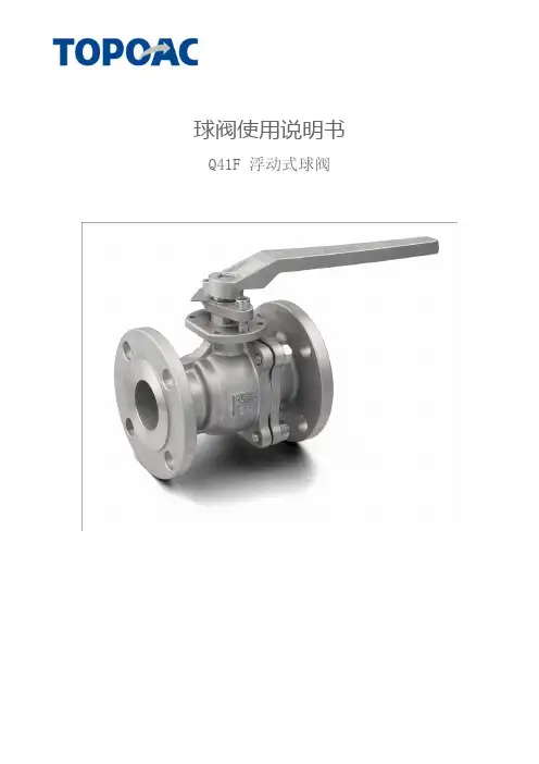
球阀使用说明书 Q41F 浮动式球阀球 阀 (Ball Valve)球阀是由旋塞演变而来的,它的启闭件为一个球体,利用球体绕阀杆的轴线旋转90度实现开启和关闭的目的。
球阀在管道上主要用于切断、分配和改变介质流动方向,设计成V 形开口的球阀还具有良好的流量调节功能。
球阀不仅结构简单,密封性好,而且在一定的公称通径范围内体积较、重量轻、材料耗阀门品种之一。
特别是在美、日、德、法、意、西、英等工业发达国家,球阀的使用非常广泛,使用品种和数量仍在继续扩大,并向高温、高压、大口径、高密封性、长寿命、优良的调节性能以及一阀多功能方向发展,其可靠性及其他性能指标均达到较高水平,并已部分取代闸阀、截止阀、节流阀。
随着球阀的技术进步,在可以预见的短时间内,特别是在石油天然气管线上、炼油裂解装置上以及核工业上将有更广泛的应用。
此外,在其他工业中的大中型口径、中低压力领域,球阀也将会成为主导的阀门类型之一。
球阀结构爆炸图序号名称数量1 阀盖 12 密封垫 13 四氟密封圈 24 螺帽 45 螺栓 46 球 17 阀体 18 内六角螺丝 29 四氟填料 410 压盖 111 阀杆 112 四氟圈(阀杆密封) 1另有定位片、手柄、蜗轮、电动头(视工况而定)球阀的优点是:(1) 具有最低的流阻(实际上为零)。
(2) 因在工作时不会卡住(在无润滑剂时),故能可靠地应用于腐蚀性介质和低沸点液体中。
(3) 在较大的压力和温度范围内,能实现完全密封。
(4) 可实现快速启闭,某些结构的启闭时间仅为0.05~0.1s,以保证能用于试验台的自动化系统中。
快速启闭阀门时,操作无冲击。
(5) 球形关闭件能在边界位置上自动定位。
(6) 工作介质在双面上密封可靠。
(7) 在全开和全闭时,球体和阀座的密封面与介质隔离,因此高速通过阀门的介质不会引起密封面的侵蚀。
(8) 结构紧凑、重量轻,可以认为它是用于低温介质系统的最合理的阀门结构。
(9) 阀体对称,尤其是焊接阀体结构,能很好地承受来自管道的应力。
1.USE: 1.1Life of valve can be maximized if the valve is used within the rated range, in accordance with pressure, temperature, and corrosion data. 2.MANUAL OPERATION: 2.1To open or close the valve, turn the handle ¼ turn (90 degrees). A.Valve in Open Position – the handle is in parallel (in-line) with the valve or pipeline. B.Valve in Closed Position – the handle is perpendicular (crossed) with the valve or pipeline.3.DISASSEMBLING & CLEANING THE VALVE: 3.1Ball valves can trap fluids in ball cavity when it is in closed position. 3.2If the valve has been used in hazardous media, it must be decontaminated before disassembly. A.Relieve the line pressure. B.Place valve in half-open position and flush the line to remove any hazardous material from valve. C.All persons involved in the removal and disassembly of the valve should wear the proper protective clothing, such as face shield, glove, apron, etc.4.REPLACING THE THRUST WASHER, PACKING, AND SEATS 4.1Before replacing the stem seal and the packing, the pipeline must be de-pressurized. 4.2Take-off the valve from the pipeline. 4.3Place valve in its’ fully open position. 4.4Take-off end cap. 4.5Close the valve and remove the seat, body seals and ball. 4.6Remove the valve stem nut, handle, gland nut and remove the valve stem through the body cavity. 4.7Remove the stem trust washer from the stem cavity. 4.8Examine all metallic sealing surfaces such as ball, stem and end cap for damage, if the ball or stem is excessively damaged, ball and stem need to be replaced.5.RE-ASSEMBLINGHaving assured that all critical surfaces and components have been inspected, cleaned and or replaced, re-assemble can begin. 5.1Place new stem seal on stem and install the stem. 5.2Install new gland packing, bushing,gland bush, belleville washer and stem nut 5.3Tighten stem nut to torque specification in Table 1.5.4 Lightly lubricate seats and body seals using a lubricant. 5.5 Re-install end cap.A-T Controls product, when properly selected, is designed to perform its intended function safely during its useful life. However, the purchaser or user of A-T Controls products should be aware that A-T Controls products might be used in numerous applications under a wide variety of industrial service conditions. Although A-T Controls can provide general guidelines, it cannot provide specific data and warnings for all possible applications. The purchaser / user must therefore assume the ultimate responsibility for the proper sizing and selection, installation, operation, and maintenance of A-T Controls products. The user should read and understand the installation operation maintenance (IOM) instructions included with the product, and train its employees and contractors in the safe use of A-T Controls products in connection with the specific application.While the information and specifications contained in this literature are believed to be accurate, they are supplied for informative purposes only. Because A-T Controls is continually improving and upgrading its product design, the specifications, dimensions and information contained in this literature are subject to change without notice. Should any question arise concerning these specifications, the purchaser/user should contact A-T Controls.For product specifications go to /A-T Controls, Inc. • 9955 International Boulevard, Cincinnati, OH 45246 • Phone: (513) 530-5175 • Fax: (513) 247-5462 • 。
Contents1.SCOPE (2)2.INSTALLATION (2)3.VALVE OPERATION (3)4.DISASSEMBLY (3)5.ASSEMBLY (4)6.REPAIR KITS (4)1.SCOPE1.1.CAUTION1.1.1.For your safety, read this manual before installation or service.1.1.2.Before installing or servicing, please ensure the line pressure has been relieved and any hazardous fluids have beendrained or purged from the system.1.1.3.Ensure that all Lockout and Tagout procedures for the system have been properly implemented.E1.2.1.Maximum results and long life of valves can be maintained under normal working conditions and according withpressure/ temperature ratings and corrosion data chart.2.INSTALLATION2.1.GENERAL INFORMATION FOR INSTALLATION2.1.1.The valve can be installed in any position on the pipeline.2.1.2.Before installation of the valve, the pipe must be flushed clean of dirt, burrs, and welding residue, or the seats and ballsurface will be damaged. The pipe must be free from tension and in proper alignment. Check to ensure that allconnections are free from defects.2.2.INSTALLATION OF THREADED VALVESe conventional sealant, such as hemp core, Teflon, etc. on threads. Apply wrench only on the hexagon of the valveends. Tightening by using the valve body or lever can seriously damage the valve. In some applications, screwedvalves are back welded on site. These valves must be treated as per instructions for the weld end valves before backwelding.2.3.INSTALLATION OF WELDED ENDS2.3.1.Tack weld the valves on the pipe in four points on both end caps.2.3.2.With the valve in the open position, (lever to be parallel to the axis of the pipe), remove all the body bolts except one.Loosen the nut on the remaining bolt. Swing the body outside the pipe. Finish welding both end caps on the pipe.2.3.3.When cooled down, clean both end caps and body surface.2.3.4.Swing the body back in position and replace the body bolts. Tighten all nuts slightly. This operation is very importantto keep the body and end caps perfectly parallel, thus preventing distortion of end caps. Tighten body bolts evenly (seesection 5.5). Make sure that maximum tightening torque is observed. Check proper operation of the valve.3.VALVE OPERATION3.1. MANUAL3.1.1.HANDLE3.1.1.1.To OPEN the valve, turn the handle counterclockwise until the handle is parallel with the pipeline and the handlehas contacted the handle stop.3.1.1.2.To CLOSE the valve, turn the handle clockwise until the handle is perpendicular with the pipeline and the handlehas contacted the handle stop.3.1.1.3.A handle lock is incorporated into the handle. To use, slide the lock into the mounting pad, in the full open orfull closed position. Insert an appropriate size lock or hasp into the handle. If it can be performed safely, try toturn the handle to ensure that the valve has been locked properly.3.1.2.GEAR3.1.2.1.To OPEN the valve, turn the handle wheel counterclockwise. The indicator will be pointing to the open positionand stop rotating when fully opened. The flow can be adjusted by stopping the indicator anywhere between openand close.3.1.2.2.To CLOSE the valve, turn the handle wheel clockwise. The indicator will be pointing to the close position andthe hand wheel will stop rotating when fully closed. The flow can be adjusted by stopping the indicatoranywhere between open and close.3.2.AUTOMATED3.2.1.A-T Controls 55 Series Ball Valves can be mounted with quarter turn actuators. Valves with actuators shall be checkedfor proper valve stem alignment. Angular or linear misalignment may result in high operational torque and unnecessarywear on the valve stem. See the actuator IOM for information on operating the actuator.4.DISASSEMBLYWARNINGCAUTION, FLUIDS CAN BE TRAPPED IN THE BODY OF THE VALVE, POSSIBLY UNDER HIGH PRESSURE. FOR YOUR SAFETY, IT IS IMPORTANT THAT PRECAUTIONS ARE TAKEN BEFORE REMOVAL OF THE VALVE FROM THE LINE OR ANY DISASSEMBLY.4.1.Remove actuator or gear if equipped.4.2.Care should be taken to not damage the surface finish of the valve components,4.3.Remove the ends (2) from the body (1) by removing the body bolts (14), body nuts (17), and lock washers (18).4.4.Remove the seats (8) and body gaskets (13) from both sides of the body (1). Once removed, with the valve in the fullyclosed position, the ball (3) should slide freely out of the body (1).4.5.If equipped, remove the handle nut (21), handle (7), and the handle stop assembly (15).4.6.While holding the stem (4) stationary, remove the packing nut (5). Once removed, the locking saddle (12), Bellevillewashers (6), and the packing bushing (9) should be free to remove.4.7.While holding the bottom of the stem (4), push the stem (4) through the inside of the valve body (1).4.8. Remove the packing set (10) and the thrust washer (11).4.9.Inspect all components for damage and, if necessary, clean or replace.5.ASSEMBLY5.1.Care should be taken to not damage the surface finish of the valve components.5.2.Place thrust washer (11) on the stem (4) and install it by going through the body (1). Insert V-style packing set (10) overstem (4) with the V pointing away from the valve (see Bill of Materials for correct orientation).5.3.Install the packing gland (10), Belleville washers (6), the locking saddle (12), and the packing nut (5). While holding thestem (4), tighten the packing nut (5) to the torque listed in the Fastener Torque Chart. Tighten further if needed in order to be able to place the locking saddle (12) over the packing nut (5).5.4.Ensure the stem (4) is in the closed position with the body tang parallel with the flow of the valve. Insert a seat (8) and bodygasket (13) in one side of the body (1). Carefully slide the ball (3) into the body (1) and insert the other seat (8) and body gasket (13).5.5.Assemble ends (2) onto body (1). Insert all body bolts (14), body nuts (17) and lock washers (18) into valve and tighten tofinger tight, making sure that the ends (2) are flat against the body (1). Tighten all body bolts (on both sides for 2-1/2” thru 4”) from the nut (17) to 50% of the max bolt torque in a star pattern. Check each body bolt (14) torque and tighten a final time to the max torque of the body bolts. It is acceptable for the torque to relax slightly over time due to relaxation of the polymer components, but the valve will still seal properly. If leakage is detected, repeat the steps for tightening the body bolts (14).5.6.If required, assemble the locking device (20), handle stop (15), handle (7), and the handle nut (21).6.REPAIR KITSRepair kits are available to replace all soft goods. See Bill of Materials for components that are included in the repair kits.7.BILL OF MATERIALSA-T Controls product, when properly selected, is designed to perform its intended function safely during its useful life. However, the purchaser or user of A-T Controls products should be aware that A-T Controls products might be used in numerous applications under a wide variety of industrial service conditions. Although A-T Controls can provide general guidelines, it cannot provide specific data and warnings for all possible applications.The purchaser / user must therefore assume the ultimate responsibility for the proper sizing and selection, installation, operation, and maintenance of A-T Controls products. The user should read and understand the installation operation maintenance (IOM) instructions included with the product and train its employees and contractors in the safe use of A-T Controls products in connection with the specific application.While the information and specifications contained in this literature are believed to be accurate, they are supplied for informative purposes only.Because A-T Controls is continually improving and upgrading its product design, the specifications, dimensions and information contained in this literature are subject to change without notice. Should any question arise concerning these specifications, the purchaser/user should contact A-T Controls.For product specifications go to https:///Downloads/。
超高压·大口径气动球阀使用说明书SUPPER HIGH-PRESSURE & LARGE-SIZE PNEUMATIC ACTIONBALL VALVE OPERATING MENUl ANSI CLASS 900、1500、2500 Lb l GB PN 160、250、320、420 kgf/cm 2 l DN 2"-36" 50-900 mm成都成高阀门有限公司CHENG DU CHENG GAO VALVE CO.,LTD.CHV®A Z超高压•大口径气动球阀 CHV 成都成高阀门有限公司-1-目 录一、产品用途...............................................................................................................................2 1.Instruction......................................................................................................................2 二、结构特点...............................................................................................................................2 2. Con struction feature......................................................................................................2 三、组成............................................................................................................................2 3. Composing....................................................................................................................2 四、工作原理....................................................................................................................2 4.Working principle...........................................................................................................2 五、安装调试与使用维护...........................................................................................................2 5. Installation and maintenance.....................................................................................................2 六、可能出现的故障及排除方法...............................................................................................3 6. Trouble Shooting.......................................................................................................................3 附图.........................................................................................................................................4 attached figure .......................................................................................................................4 球阀Cv 值表..........................................................................................................................5 Cv flow coefficients.................................................................................................................5 固定球阀操作扭矩表.............................................................................................................6 Trunnion Mounted Ball V alve Open torque.. (6)超高压•大口径气动球阀 CHV 成都成高阀门有限公司·2·一、产品用途: 1.Instruction:CHV 制造超高压、大口径气动球阀是气动执行器的一种新产品,它具有新颖独特的结构和专门的控制系统设计,它与气控或电控组合仪表配套,广泛地应用于冶金、矿山、石油、化工、电力、轻工、船舶等工业部门和自动化控制系统中,适用于气体、液体或含有悬浮颗粒流体的流量控制或切断。
flowserve球阀阀门说明书
一、产品概述
Flowserve球阀阀门是一种常用的流体控制设备,具有结构紧凑、操作简便、密封性能好等特点。
本说明书旨在向用户介绍Flowserve 球阀阀门的基本知识、安装使用方法、维护保养等内容,以帮助用户正确地使用和维护该设备。
二、产品结构
Flowserve球阀阀门主要由阀体、球体、密封圈、阀杆等部分组成。
其中,球体在阀体内转动,通过密封圈实现密封,以达到控制流体流向和流量的目的。
三、安装使用方法
1. 安装前检查:在安装前应检查球阀是否完好无损,各部件是否齐全,没有明显的机械损伤或裂纹等现象。
2. 安装位置:球阀应安装在流体流动方向上,尽可能避免安装在管道的最高点或最低点。
同时,应考虑便于操作和维修的位置。
3. 安装方式:根据球阀的结构和尺寸,可以采用法兰连接或螺纹连接等方式进行安装。
在安装时应注意保证球阀的垂直度和水平度,避免过大的压力或剪切力作用在球阀上。
4. 操作使用:在操作球阀时,应先确认流体流向,然后旋转阀杆,使球体在阀体内转动,以达到控制流体流向和流量的目的。
在操作过程中应注意观察是否有异常声音或振动等现象,如有异常应及时
停用检查。
四、维护保养
1. 定期检查:应定期对球阀进行检查,包括检查球体、密封圈、阀杆等部位是否有磨损或损坏现象,以及是否有渗漏或堵塞等现象。
如有问题应及时处理。
球阀使用及维护1.前言感谢您选择我公司阀门产品。
作为一种承压设备,当阀门用于输送流体及易燃易爆气体时,由于泄露或使用不当而存在一些安全隐患,为了安全考虑,用户使用时应阅读本说明书,以了解阀门在运输、放置、安装、维护及安全方面应该注意的事项和必须遵守的原则。
2.范围本使用说明书包括了公称通径NPS 2~48、压力等级Class150~2500法兰端连接、承插焊端连接的两片式、三片式硬密封、软密封锻钢固定球阀;适用介质水、油、汽等介质;操作方式包括齿轮、手柄、电动执行机构、液动、气动和气液联动执行机构。
3.产品描述和用户须知3.1技术要求—球阀作为一种标准产品来设计,由于它的适用工况范围较广所以并不考虑每一个细节的工作条件。
—美标球阀设计参照API 6D,阀门材料的选择符合ASME B16.34 压力—温度额定值的要求;国标球阀的设计参照GB/T 12237或GB/T 19672,阀门的材料选择符合GB/T 12224压力—温度额定值的要求。
—阀门密封材料应根据介质对材料的腐蚀性和工况耐磨损的要求而选择,参照API 6D、GB/T 12237或GB/T 19672的规定。
—阀门设计时应有防静电装置及防火结构,放火实验设备符合API 607及API 6FA 规范,并已通过英国的劳氏船级社认证。
—阀门不含轻金属(例如镁),各零部件通过相互接触形成导电通路,通过管道流向大地,以防止静电积累。
—阀门根据它的型号、扭矩、及操作要求配以手轮、齿轮、或电动头。
3.2 用户须知3.2.1 概述3.2.1.1 任何场合,应首先保证人身安全。
3.2.1.2 使用阀门时允许工作压力应符合 ASME B16.34 或GB/T12224压力—温度额定值的规定。
3.2.1.3 选择阀门材料时应考虑工作介质对材料的腐蚀性和工况对耐磨损的要求。
3.2.1.4 工作介质是易燃/易爆的,要限制工作温度。
3.2.1.5 当维修/维护时,应先打开泄放阀或泄放螺塞,以泄掉中腔压力。
Swagelok® Alternative Fuel Ser vice (AFS) Ball ValvesFor High-Pressure, High-Flow ApplicationsSwagelok AFS Ball Valves■ Working pressures up to 6000 psig (413 bar)■ Flow coefficients (C v) from 4.0 to 13.8■ Fractional and metric Swagelok tube fittings; ISO and NPT pipe end connections available■ 316 stainless steel body and end connections■ Manual and pneumatic actuation2 Swagelok Alternative Fuel Service (AFS) Ball ValvesCertifications■ ANSI / AGA NGV 3.1 / CGA 12.3-M95,Classification: Manual valve Pressure: 4500 psig (310 bar)Temperature: –40 to 250°F (–40 to 121°C)■ ANSI / IAS NGV 4.6 / CSA 12.56-M99,Classification: Class APressure: 4500 psig (310 bar)Temperature: –40 to 185°F (–40 to 85°C)■ ECE R110 Manual Service Valve Type ApprovalClassification: Class 0Pressure: 3770 psig (260 bar)Temperature: –40 to 248°F (–40 to 120°C)■ Certifications do not include attachments to the valve,such as actuators or a different handle mechanism.Features■ High flow—C v from 4.0 to 13.8■ All wetted components arecompatible with hydrogen andcompressed natural gas (CNG)■ Maximum pressure rating: 6000 psig(413 bar)■ Temperature rating: –40 to 250°F(–40 to 121°C)■ Low operating torque■ No packing adjustment required ■ Field repairable with seal kitSwagelok Alternative Fuel Service (AFS) Ball ValvesImportant InformationAbout Swagelok AFS Ball ValvesSwagelok AFS ball valves are designed to be used inthe fully open or fully closed position.Valves that have not been cycled for a period of timemay have a higher initial actuation torque.Pressure-Temperature RatingsRatings are based on ASME Code for Pressure Piping B31.3, Process Piping. To determine working pressure ratings in accordance with ASME B31.1, Power Piping, for 316 stainless steel, multiply pressure by:■ 0.86 for temperatures from 100 to 200°F (37 to 93°C).■ 0.82 for temperatures up to 250°F (121°C).consistent, low actuation torquechemical compatibilitypressure systemsSwagelok Alternative Fuel Service (AFS) Ball Valves 3USAUSAEUROFlow Data at 70°F (20°C)NitrogenFlow,stdL/minNitrogenFlow,stdft3/minPressure Drop, psiPressure Drop, barInlet Pressure 3600 psig (248 bar)Inlet Pressure 5000 psig (344 bar)NitrogenFlow,stdL/minNitrogenFlow,stdft3/minPressure Drop, psiPressure Drop, barMaterials of ConstructionWetted components listed in italics.412510113131418678919121615174 Swagelok Alternative Fuel Service (AFS) Ball ValvesOrdering Information and DimensionsSelect an ordering number.Dimensions, in inches (millimeters), are for reference only and are subject to change.➀ V alves can be ordered with two different end connections. Contact your authorized Swagelok sales and service representative.➁ N ot available with AGA, IAS, and ECE R110 certifications; not recommended for panel mounting; not available with pneumatic actuator.➂ T hread type ISO/BSP (tapered), based on DIN 3852, Swagelok RT fittings.See specifications ISO 7/1, BS EN ISO 10226-1, and JIS B0203.Options and AccessoriesLocking Brackets■ Designed to lock valve in the openand closed position■ Accommodates shackle diametersup to 0.344 in. (8.7 mm)■ To order the locking bracket factory-assembled on a valve, add -LH to the valve ordering number.Example: SS-AFSS6-LHTo order the locking bracket for fieldassembly, use kit ordering number: SS-51K-AFS-LHHandle OptionsBlack nylon directional handles are standard.■ To order adirectional handle ofanother color,add a handleto the valve ordering number.Example: SS-AFSS6-RD■ To order a nylon ovalhandle, add -K to the valve ordering number.Example: SS-AFSS6-K ■ To order a black aluminumdirectional handle, add -AHD to the valve ordering number.Example: SS-AFSS6-AHDHandle KitsThe replacement handle kit includes a handle with set screw and instructions.■ Black nylon directional handle kitordering number: NY-5K-AFS-BKTo order a nylon directional handle kitin a color other than black, replace -BK in the kit ordering number with a handle color designator.Example: NY-5K-AFS -RD ■ Nylon oval handle kit orderingnumber: NY-5K-AFSK-BK■ Black aluminum directional handle kitordering number: A-5K-AFS-BKStem Seal Material OptionUltralow-temperature fluorocarbon FKM is standard. Ultralow-temperature nitrile (Buna C) is available as an option to enhance valve cycle life. Valves with ultralow-temperature nitrile have atemperature rating of –40 to 200°F (–40 to 93°C) and are not certified to AGA, IAS, or ECE R110.To order, add -BCS to the valve ordering number.Example. SS-AFSS6-BCSSwagelok Alternative Fuel Service (AFS) Ball Valves 5SwagelokPneumatic ActuatorsThe Swagelok rack and pinion pneumatic actuator is compact,lightweight, easily mountable, and can be operated with standard shop air. The actuators are available in spring-return and double-acting modes. For technical data, including materials of construction, air displacement, and weight, see the Swagelok Ball Valve Actuation Options catalog, MS-02-343.DimensionsDimensions, in inches (millimeters), are for reference only and are subject to change.Actuated assemblies mustbe properly aligned andsupported. Improper alignment or inadequate support of the actuated assembly may result in shorter valve life.Actuator Pressure at Maximum System PressureRequired pressures based on valve performance using pressurized air or nitrogen.For dual-mounted assemblies (two valves mounted to one actuator), add DM to the ordering number. Example: SS-AFSS6-33DHT DMActuator Service Ratings➀ M aximum working pressure for valves mounted to low-temperature service actuators is4500 psig (310 bar).Factory-Assembled ActuatorsTypical Ordering NumberD = Double actingC = Normally closed spring return O = Normally open spring returnD H TActuator Service N one = StandardHT = High temperature LT = Low temperature ➀➀ M aximum working pressurefor valves mounted to low-temperature service actuators is 4500 psig (310 bar).Ordering InformationActuators for Field AssemblyOrder one actuator kit and one mounting bracket kit for each valve.Mounting bracket kit ordering number:MS-MB-AFS-133➀ M aximum working pressure for valves mounted to low-temperature service actuators is 4500 psig (310 bar).6 Swagelok Alternative Fuel Service (AFS) Ball ValvesISO 5211-Compliant Pneumatic ActuatorsSwagelok ISO 5211-compliant rack and pinion pneumatic actuators are available in spring-return and double-acting modes.For technical data, including actuator materials of construction and weight, see the Swagelok Ball Valve Actuation Options catalog, MS-02-343.For additional information on selecting and sizing ISO 5211-compliantactuators, see the Actuated Ball Valve Selection Guide—ISO 5211-Compliant Actuator Mounting Bracket Kits, MS-02-136.Factory-Assembled ActuatorsTypical Ordering NumberD = Double actingC4 = Normally closed spring return O4 = Normally open spring returnD H TActuator Service N one = StandardHT = High temperatureActuated assemblies mustbe properly aligned andsupported. Improper alignment or inadequate support of the actuated assembly may result in shorter valve life.Ordering InformationActuators for Field AssemblyOrder one actuator kit and one mounting bracket kit for each valve.Mounting bracket kit ordering number:SS-MB-AFS-F05-14DIN-MActuator Service RatingsDimensionsDimensions, in inches (millimeters), are for reference only and are subject to change.Swagelok Alternative Fuel Service (AFS) Ball Valves 7Maintenance KitsKit components are of the same materials and grades listed in Materials of Construction, page 3.Seat Seal KitsThe seat seal kit contains two seats, seat O-rings, seatbackup rings, seat springs, end screw gaskets, lubricant with Material Safety Data Sheet (MSDS), and instructions.Kit ordering number: SS-9K-AFSStem and Seat Seal KitsThe stem and seat seal kit contains a stem O-ring, two guide rings, stem backup ring, thrust washer, packing bolt gasket, two seats, seat O-rings, seat backup rings, seat springs, end screw gaskets, lubricant with Material Safety Data Sheet (MSDS), and instructions.Kit ordering number: SS-91K-AFSTo order a kit with a stem O-ring of optional ultralow-temperature nitrile (Buna C) material, use kit ordering number: SS-91K-AFS-BCSOptions for ISO 5211-Compliant andSwagelok Pneumatic ActuatorsSwagelok offers a range of accessories to enhance instrumentation and process ball valve performance and control, including solenoid valves, limit switches, and position sensors. Factory assemblies and kits for field assembly are available.For more information, see the Swagelok Ball ValveActuation Options catalog, MS-02-343.Safe Product SelectionWhen selecting a product, the total system design must be considered to ensure safe, trouble-free performance. Function, material compatibility, adequate ratings,proper installation, operation, and maintenance are the responsibilities of the system designer and user.Warranty InformationSwagelok products are backed by The Swagelok Limited Lifetime Warranty. For a copy, visit or contact your authorized Swagelok representative.Swagelok—TM Swagelok Company © 2004–2014 Swagelok Company Printed in U.S.A., AGS November 2014, R11MS-02-303。
球阀使用说明书Q41F 浮动式球阀浙江福泰阀门有限公司球阀(Ball Valve)球阀是由旋塞演变而来的,它的启闭件为一个球体,利用球体绕阀杆的轴线旋转90度实现开启和关闭的目的。
球阀在管道上主要用于切断、分配和改变介质流动方向,设计成V 形开口的球阀还具有良好的流量调节功能。
球阀不仅结构简单,密封性好,而且在一定的公称通径范围内体积较、重量轻、材料耗阀门品种之一。
特别是在美、日、德、法、意、西、英等工业发达国家,球阀的使用非常广泛,使用品种和数量仍在继续扩大,并向高温、高压、大口径、高密封性、长寿命、优良的调节性能以及一阀多功能方向发展,其可靠性及其他性能指标均达到较高水平,并已部分取代闸阀、截止阀、节流阀。
随着球阀的技术进步,在可以预见的短时间内,特别是在石油天然气管线上、炼油裂解装置上以及核工业上将有更广泛的应用。
此外,在其他工业中的大中型口径、中低压力领域,球阀也将会成为主导的阀门类型之一。
球阀结构图球阀的优点是:(1)具有最低的流阻(实际上为零)。
(2)因在工作时不会卡住(在无润滑剂时),故能可靠地应用于腐蚀性介质和低沸点液体中。
(3)在较大的压力和温度范围内,能实现完全密封。
(4)可实现快速启闭,某些结构的启闭时间仅为0.05~0.1s,以保证能用于试验台的自动化系统中。
快速启闭阀门时,操作无冲击。
(5)球形关闭件能在边界位置上自动定位。
(6)工作介质在双面上密封可靠。
(7)在全开和全闭时,球体和阀座的密封面与介质隔离,因此高速通过阀门的介质不会引起密封面的侵蚀。
(8)结构紧凑、重量轻,可以认为它是用于低温介质系统的最合理的阀门结构。
(9)阀体对称,尤其是焊接阀体结构,能很好地承受来自管道的应力。
(10)关闭件能承受关闭时的高压差。
(11)全焊接阀体的球阀,可以直埋于地下,使阀门内件不受浸蚀,最高使用寿命可达30年,是石油、天然气管线最理想的阀门。
由于球阀的以上优点,所以适用范围很广,球阀可适用于:(1)公称通径从8mm到1200mm。
Contents1SCOPE (2)2INSTALLATION (2)3VALVE OPERATION (3)4DISASSEMBLY (4)5ASSEMBLY (4)6REPAIR KITS (5)7BILL OF MATERIALS (6)1SCOPE1.1CAUTION1.1.1For your safety, read this manual before installation or servicing.1.1.2Before installing or servicing, please ensure the line pressure has been relieved and any hazardous fluids havebeen drained or purged from the system.1.1.3Ensure that all Lockout and Tagout procedures for the system have been properly implemented.1.2USE1.2.1A-T Controls 77-Series Ball Valve are available in Hygienic Ferrule Ends (½” & ¾” Type A, 1”-4” Type B) orExtended Tube Butt Weld Ends.1.2.2Maximum results and optimum valve life can be maintained under normal service conditions and in accordancewith pressure/temperature ratings and corrosion data charts.2INSTALLATION2.2A-T Controls 77-Series Ball Valves are bi-directional and can be installed with the flow in either direction. Thevalve can be mounted in any position so that the handle, gear, or actuator has proper clearance, allows foroptimal drainage, can be easily accessed, and the open/close indicator can be viewed. If the gear is equipped witha chain wheel, the valve shall be mounted in a way so that the chain does not come in contact with the valve orpipeline.2.3Before installation of the valves, the pipe must be flushed clean of dirt, burrs, and welding residues. Failure to doso can cause the seats, sealing surfaces, and internal polish to be damaged.2.4The pipe must be free from tension and in proper alignment.2.5Before installation of the valves, check to ensure that all connections are free from defects.2.6Be sure to consult with supplier of your clamps and gaskets to be used on the hygienic ends for the propermaterial, pressure rating, and clamp torque for your process. Over torqueing clamps may result in damage to the ferrule end.2.7Disassembly of the valve is not necessary for tube end valves. However, caution should be taken to ensure thatthe heat source does not come in contact with the sealing components of the valve in excess of the sealingcomponent temperature limitation.3VALVE OPERATION3.1MANUAL3.1.1HandleTo open the valve, turn the handle counter-clockwise until the handle is parallel with the pipeline andthe handle has contacted the handle stop.To close the valve, turn the handle clockwise until the handle is perpendicular with the pipeline and thehandle has contact the handle stop.A handle lock is incorporated into the handle. To use slide the lock into the mounting pad, in the fullopen or full closed position. Insert an appropriate size lock or hasp into the hole in the handle. If it canbe performed safely, try to turn to ensure that the valve has been locked properly.3.1.2GearTo OPEN the valve; turn the hand wheel counter-clockwise. The indicator will be pointing to the openposition and stop rotating when fully opened. The flow can be adjusted by stopping the indicatoranywhere between open and close.To CLOSE the valve; turn the hand wheel clockwise. The indicator will be pointing to the close positionand the hand wheel will stop rotating when fully closed. The flow can be adjusted by stopping theindicator anywhere between open and close.3.2AUTOMATEDA-T Controls 77-Series Ball Valves can be mounted with quarter turn actuators. Valves with actuatorsshall be checked for proper valve stem alignment. Angular or linear misalignments may result in highoperational torque and unnecessary wear on the valve stem. See the actuator IOM for information onoperating the actuator.4DISASSEMBLYWARNINGCAUTION, FLUIDS CAN BE TRAPPED IN THE BODY OF THE VALVE, POSSIBILY UNDER HIGH PRESSURE. FOR YOUR SAFETY, IT IS IMPORTANT THAT PRECAUTIONS ARE TAKEN BEFORE REMOVAL OF THE VALVE FROM THE LINE OR ANY DISASSEMBLY.4.1Remove actuator or gear if equipped.4.2Care should be taken to not damage the surface finish of the valve components.4.3Remove the ends (2) from the body by removing the body bolts (18) and body nuts (19).4.4Remove the seat (4) and body gasket (5) from both sides of the body (1). Once removed, with the valve in the fullyclosed position, the ball (3) should slide freely out of the body (1).4.5If equipped, remove the handle nut (13), handle (15), and handle stop assembly (22).4.6While holding the stem (7) stationary, remove the packing nut (13). Once removed, the locking saddle (12),Belleville washers (11) and packing bushing (10) should be free to remove.4.7While holding the bottom of the stem (7), push the stem (7) through the inside of the valve body (1).4.8Remove the packing set (8) and stem seal (6).4.9Inspect all components for damage and if necessary clean or replace.5ASSEMBLY5.1Care should be taken to not damage the surface finish of the valve components.5.2Place stem seal (6) on the stem (7) and install it by going through the body (1). Insert V-Style packing set (8) overstem (7) with the V pointing away from the valve (see Bill of Materials for correct orientation).5.3Install the packing gland (10), the Belleville washers (11), locking saddle (12), and packing nut (13). While holdingthe stem (7), tighten the packing nut (13) to the torque listed in the Fastener Torque Chart. Tighten further ifneeded in order to be able to bend the locking saddle (12) over a flat side of the packing nut (13).5.4Ensure that the stem (7) is in the closed position with the bottom tang parallel with the flow of the valve. Insert aseat (4) and body gasket (5) in one side of the body (1). Carefully slide the ball (3) into body (1) and insert the other seat (4) and body gasket (5).5.5Assemble ends (2) onto body (1). Insert all body bolts (18) and nuts (19) into valve and tighten to finger tight,making sure that the ends (2) are flat against the body (1). Tighten all bolts (18) (on both sides for valves 2-1/2”- 4”) from the nut (19) side (if equipped) in a star pattern to 50% of the final torque shown in the Fastener Torque Chart. Using the handle (15) or an adjustable wrench, cycle the valve 3 times. Tighten all of the body bolts (18) to the final torque in a star pattern. Cycle the valve 3 times again. Check each body bolt torque (18) and tighten if needed a final time. It is acceptable for the torque to relax slightly over time due to relaxation of the polymer components, but the valve will still seal properly. If leakage is detected, repeat the steps for tightening the body bolts.5.6If required, assemble the handle stop assembly (16), handle (15), and handle nut (13).Valve SizeTorque of Body Bolts (In-lbs.) Torque of Stem Nut(In-lbs.) 50% of Final Torque Final Torque1/2" 56 113 783/4" 61 122 781" 69 139 1221-1/2" 156 312 1652" 217 434 1652-1/2" 347 694 1913" 390 781 1914" 390 781 2176REPAIR KITSRepair kits are available to replace all soft goods. See Bill of Materials for components that are included in the repair kits.7BILL OF MATERIALSA-T Controls product, when properly selected, is designed to perform its intended function safely during its useful life. However, the purchaser or user of A-T Controls products should be aware that A-T Controls products might be used in numerous applications under a wide variety of industrial service conditions. Although A-T Controls can provide general guidelines, it cannot provide specific data and warnings for all possible applications. The purchaser / user must therefore assume the ultimate responsibility for the proper sizing and selection, installation, operation, and maintenance of A-T Controls products. The user should read and understand the installation operation maintenance (IOM) instructions included with the product and train its employees and contractors in the safe use of A-T Controls products in connection with the specific application.While the information and specifications contained in this literature are believed to be accurate, they are supplied for informative purposes only. Because A-T Controls is continually improving and upgrading its product design, the specifications, dimensions and information contained in this literature are subject to change without notice. Should any question arise concerning these specifications, the purchaser/user should contact A-T Controls.For product specifications go to https:///Downloads/A-T Controls, Inc. • 9955 International Boulevard, Cincinnati, OH 45246 • Phone: (513) 530-5175 • Fax: (513) 247-5462 • 。
The Series BV2MB is an economical hand lever ball valve for commer-cial and general industrial use. The Series BV2MB is perfect for water shutoff applications. Valve body, body cap, and ball are made of quality brass. Seats and stem packing are constructed of TFE for long lasting service. Blowout-proof stem provides safety in the event of overpressure.Full port design allows for maximum Cv and minimal pressure drop.INSTALLATIONPrior to installation, inspect valve and pipe ends to make sure they are free from debris. Material trapped inside the valve can cause damage to the seats and result in leakage. Clean pipe ends and check for proper threading to prevent damage to valve internals.Use a PTFE based thread sealant applied to the pipe threads. With valve in the OPEN position, install pipe. Use a smooth wrench on the hex portion of the valve, not the valve body, to tighten. Use pipe wrench-es on pipe and pipe fittings only.OPERATIONThese valves are bi-directional and can be installed with flow in either direction. Rotate the handle 90 degrees counterclockwise to open and 90 degrees clockwise to close. Check to make sure the process media is compatible with the valve materials. See “Specifications”. Do not exceed pressure or temperature maximum ratings.SPECIFICATIONS Body: Two-Piece.End Connections: 1/4˝ to 3˝ female NPT.Pressure Limit: 1/4˝ to 1˝: 600 psi (41.4 bar), 1-1/4˝ to 2˝: 400 psi (27.6 bar), 2-1/2˝ to 3˝: 200 psi (13.8 bar) WOG.Wetted Materials: Body and body cap: forged brass (ASTM B283-C37700); ball and stem: brass; seat and packing: TFE.Temperature Limit: 10 to 200°F (-12 to 93°C).Other Materials:Body seal: rubber; handle: plated steel; nut and gasket: brass.MAINTENANCEThe Series BV2MB is a non-repairable valve. The only maintenance required is the occasional tightening of the packing gland nut.©Copyright 2010 Dwyer Instruments, Inc. Printed in U.S.A. 8/10 FR# R2-443324-00 Rev. 1。
球阀使用维护说明书
. . ..
.资料. . .
浮动球阀结构示意图 固定球阀结构示意图
LOC K
一、用途
本系列阀门安装在水、汽、天然气、煤气、油品等介质管道上作为接通和截断用。
二、特点
(一)浮动球阀
1. 阀门采用中部法兰及PTFE(聚四氟乙烯)或PPL(对位聚苯)垫片的密封结构,浮动球,两端法兰连接,扳
手操作或蜗轮、气动、电动操作,亦可配置信号装置,实现远程控制。
2. 阀座为PTFE(聚四氟乙烯)或PPL(对位聚苯),其摩擦系数小,能有效的降低球阀的开关力矩。
3. 阀杆经调质处理,有良好的机械性能和抗擦伤性。
4. 可根据使用工况或用户要求设置防火防静电结构,还可以带锁,防止误操作。
(二)固定球阀
1. 阀门采用中部法兰及金属石墨缠绕垫片或O形圈的密封结构,固定球,两端法兰连接。
2. 阀座为摩擦系数小且有自润滑和耐腐蚀的PTFE(聚四氟乙烯)或PPL(对位聚苯)。
阀座支承圈用浮动结构,
弹簧作用力可使阀门在低压情况下密封。
3. 阀杆经调质处理,有良好的机械性能和抗擦伤性。
4. 有上下阀杆承受主要载荷,所以在关闭位置,球与阀座之间的受载情况得到缓解,保护了密封副免受损伤。
5. 该阀门根据用户要求可设置注脂装置。
6. 双阻断及泄放功能:阀门采用阀前密封,两个阀座能独立切断进口端和出口端的介质,实现双阻断功能;
当球阀关闭时,即使阀门进出口两端同时受压,阀门中腔和两端通道也可以被相互阻断,中腔的剩余介质可以通过泄放阀排出。
三、主要零件材料
四、主要性能规及相关标准
(一)、主要性能规
(二)、相关标准
1、设计制造标准:GB/T 12237-2007;API 6D、BS5351
2、结构长度:QB/YX-2007(企业标准);
GB/T12221-2005 ;ANSI B16.10
-2-
3、法兰的结构型式及尺寸:JB/T 79-1994 ;ANSI B16.5、ANSI B16.47
4、阀门的检验与压力试验:JB/T 9092-1999;API 598
五、安装使用与维护保养
1、安装使用
1.1安装前应仔细核对阀门铭牌容,保证阀门的类型,尺寸、阀座材料、使用温度等额定值符合管道的使用情
况。
1.2安装使用前最好能对球阀所有连接处的螺栓进行检查,保证其已均匀拧紧。
并检查填料是否压紧而又密封。
1.3安装前应对管线进行清扫,去除管线中油污,焊渣等杂质。
1.4阀门在搬运中应轻取轻放,禁止抛扔或跌落。
1.5大型阀门应安装固定支架,保证阀门安装后,整条管线的稳定性和安全性。
1.6阀门安装时,应取下阀门两端的防尘盖。
1.7阀门往管道上安装时,在法兰间应垫进合适的垫片,取相应的规格的螺栓把法兰对角均匀拧紧。
1.8如阀门安装后发现阀杆密封处有渗漏,可能是在运输过程中震动和温度变化引起填料松弛,拧紧填料压盖
螺母即可,并注意给填料加润滑油,以减轻操作力矩。
1.9阀门的开启和关闭由手柄(手轮)来控制,当顺时针旋转手柄(手轮)时球体在阀杆的作用下顺时针旋转
运动关闭阀门,逆时针则旋转手柄(手轮)则开启阀门。
1.10阀门可安装在任意位置,介质可从任意端进入。
1.11如阀门为非手动装置,必须设置好执行机构的空间位置,以便在意外情况的人工操作及维修,并在正式投
产前对电动驱动装置进行检查和测试。
2、储存与维护保养
2.1在干燥通风的室,两端应盖上防尘盖,以保证阀门的腔清洁。
2.2长期存放应在阀门密封面涂防锈油,并定期检查。
2.3 大型阀门存放在室外保管时,应将其支撑起来,不要与地面接触,并用塑料薄腊覆盖保护。
2.4长期存放的阀门重新使用时,应检查填料是否失效,并对各转动部位加注润滑油。
2.5阀门在使用中应定期检查以保证阀门的使用性能,包括定期拧紧阀门填料压盖螺母,以补偿阀杆磨损;如
果阀门与电动装置使用无松动联轴器,则要先松开联轴器,然后拧紧填料压盖螺母。
2.6阀门的保修期。
阀门在投入使用一年,但不超过发货18个月,如确因材料缺陷,制造质量,在正常使用
中的损坏,经本公司质检部门确认后,在保修期负责保修,包括更换垫片、填料、球体(按需要)、阀座等密封付。
2.7保持阀门的工作环境清洁,以延长阀门的使用寿命。
★2.8球阀在使用过程中应全开或全关,禁止作调节阀用,否则会缩短阀门的使用寿命。
-3-
七、主要连接尺寸
(1)浮动球阀
Q(3)41F-16、Q(3)41PPL-16
-4- Q(3)41F-150Lb、Q(3)41PPL-150Lb
(2)固定球阀
Q(3)47F-16 Q(3)47PPL-16
Q(3)47F-25 Q(3)47PPL-25
-6-。