eDCAP-615A PT保护测控装置 使用说明书
- 格式:pdf
- 大小:1.58 MB
- 文档页数:31

保护控制器操作使⽤⽅法(精)六、保护控制器操作使⽤⽅法1.⾯板及按键说明 1.1显⽰窗第⼀显⽰窗在参数设定状态下显⽰设定参数;第⼆、第三、第四显⽰窗在运⾏状态下分别显⽰三相电流和三相电压。
1.2指⽰灯⼋个指⽰灯,指⽰电机故障停⽌原因:启动失败、短路堵转、缺相、三相不平衡、定/反时限、接地、⽋过压、1.3按键设置键:在测量(运⾏)状态下,按住2秒钟以上不松开则进⼊设置状态。
在设置状态下,显⽰参数符号时,按住2秒钟以上不松开进⼊下⼀组参数或返回测量状态。
左键:在测量状态下切换显⽰电流、电压。
在设置状态下,⽤于调出原有参数或移动修改位。
确认键、复位键:在测量状态下作为故障恢复键使⽤。
在设置状态下,⽤于存⼊修改好的参数值。
增加键:在设置状态下,⽤于增加参数数值或改变设置类型。
减少键:在设置状态下,⽤于减少参数数值或改变设置类型。
1.4参数设置说明仪表的参数被分为六组,⼆、三、四、五、六组参数受密码控制,未设置密码时不能进⼊。
进⼊设置状态后,若1分钟以上不进⾏按键操作,仪表将⾃动退出设置状态。
1.5参数设置⽅法①设置键,不松开,直到显⽰0A 。
②按键进⼊修改状态,在、键的配合下将数值修改为1111 ③按键,完成密码设置。
④按住设置键,不松开,顺序进⼊下⼀组参数,仪表显⽰每组第⼀个参数的符号。
⑤进⼊需要设置参数所在的组,按键顺序循环选择本组需设置的参数。
⑥按键调出当前参数的原设定值,闪烁位为修改位。
⑦通过键移动修改位、增值、键减值,将参数修改为需要的值。
* 以符号形式表⽰参数值的参数,在修改时,闪烁位应处于末位。
⑧按键存⼊修改好的参数,并转⼊下⼀参数。
⑨重复⑤-⑧步,可设置本组的其他参数:在显⽰参数符号时,按住设置键不松开,直到退出参数的设置状态。
七、参数⼀览表该表列出了仪表的基本参数。
出⼚设定参数只是参考值,⽤户可以根据电机情况进⾏修改。
在出⼚设定⼀栏有“****”号的参数,⽤户必须设定。
⼋.仪表(参数)使⽤说明参数⼀览表说明:注1:电流互感器的选择:建议⼀次电流按电机额定电流的8倍以上选择变⽐,这样有利于保证互感器和仪表的过载能⼒注2:调校:调校可以减少由于互感器、引线等引起误差,提⾼系统的测量精度。
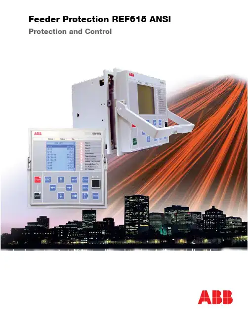
Feeder Protection REF615 ANSIABB2Standardized communicationREF615 supports the new IEC 61850 standard for inter-device communication in substations. The relay also supports the industry standard DNP3.0 and Modbus ® protocols.The implementation of the IEC 61850 substation communication standard in REF615 encompasses both vertical and horizontal communication, including GOOSE messaging and parameter setting according to IEC 61850-8-1. The substation configuration language enables the use of engineering tools for automated configuration, commissioning and maintenance of substation devices.Bus protection via GOOSEThe REF615 IEC 61850 implementation includes GOOSE messaging for fast horizontal relay-to-relay communication. Applying GOOSE communication to the REF615 relays of the incoming and outgoing feeders of a substation, a stable, reliable and high-speed bus protection system can be realized. The cost-effective GOOSE-based bus protection is obtained just by configuring the relays and the operational availability of the protection is assured by continuous supervision of the protection relays and their GOOSE messaging over the station communication network. Costs are reduced since no separate physical input and output hard-wiring is needed for horizontal communication between the relays.IEC 61850-based Connectivity andInteroperability for Distribution SubstationsArea of applicationThe REF615 is a powerful and simple feeder protection relay perfectly aligned for the protection, measurement and supervision of utility substations and industrial power systems. Engineered from the ground up, the new feeder protection relay has been designed to unleash the full potential of the IEC 61850 standard for communication and interoperability of substation automation devices.Unique REF615 features:• High impedance (HIZ) fault detection • Arc flash detection (AFD)• Thermal overload protection of feeder cable • Ring-lug terminals for all inputs and outputs • Large LCD screen with clearly visible font• Environmentally friendly design with RoHS complianceProtection and controlThe REF615 is the most powerful, most advanced and simplest feeder protection relay in its class, perfectly offering time and instantaneous overcurrent, negative sequence overcurrent, phase discontinuity, breaker failure and thermal overloadprotection. The relay also features optional high impedance fault (HIZ) and sensitive earth fault (SEF) protection for grounded and ungrounded distribution systems. Also, the relay incorporates a flexible three-phase multi-shot auto-reclose function for automatic feeder restoration in temporary faults on overhead lines.Enhanced with safety options, the relay offers a three-channel arc-fault detection system for supervision of the switchgear circuit breaker, cable and busbar compartments.The REF615 also integrates basic control functionality, which facilitates the control of one circuit breaker via the relay’s front panel human machine interface (HMI) or remote control system. To protect the relay from unauthorized access and to maintain the integrity of information, the relay has been provided with a four-level, role-based user authentication system, with individual passwords for the viewer, operator, engineer and administrator level. The access control system applies to the front panel HMI, embedded web browser based HMI and the PCM600 relay setting and configuration tool.ABB3disturbance handling1V A D 386601-F L R e v . D D e c e m b e r 2008© C o p y r i g h t 2007, 2008 A B B . A l l r i g h t s r e s e r v e d.• Three phase currents: 5/1 A • Ground current: 5/1 A or 0.2 A• Rated frequency: 60/50 Hz programmable Binary inputs and outputs• Four binary inputs with common ground • Two NO double-pole outputs with TCM • Two NO single-pole outputs • One Form C signal output• One Form C self-check alarm output• Additional seven binary inputs plus three binaryoutputs (available as an option)• IEC 61850-8-1 with GOOSE messaging • DNP3.0 Level 2+ over TCP/IP • Modbus over TCP/IP• Time synchronization via SNTP (primary and backup servers)• Optional serial RS-485 port programmable for DNP3.0 Level 2+ orModbus RTU• IRIG-B time synchronization with the RS-485 optionControl voltage• Option 1: 48 ... 250 V dc, 100 … 240 V ac • Option 2: 24 ... 60 V dcProduct dimensions and weights• Frame: 6.97” (177 mm) W x 6.97” (177 mm) H• Case: 6.57” (165 mm) W x 6.30” (160 mm) H x 6.10” (155 mm)• Weight: Relay - 7.72 lbs. (3.5 kg); Draw-out unit - 3.97 lbs. (1.8 kg) Tools• PCM600 V2.0 SP1 for setting, configuration and data retrieval • COM600 Station Automation series products V3.2• Web browser based user interface (IE 6.0 or later)ABB Inc.Distribution Automation7036 Snowdrift Road Suite 2Allentown, PA USAPhone: +1 610 395-7333Fax: +1 610 395-1055/substationautomation。

微机继电保护测试仪使用说明书目录目录 (1)第一部分微机继电保护测试仪使用说明 (3)第一章装置特点与技术参数 (4)第二章装置硬件结构 (6)第三章单机操作模块功能说明 (8)第四章外接PC机操作说明 (21)第二部分继保软件操作说明 (21)第五章软件操作方法简介 (22)第六章交流试验 (24)第七章直流试验 (32)第八章状态系列 (34)第九章谐波叠加试验 (38)第十章频率及高低周试验 (41)第十一章功率方向及阻抗试验 (45)第十二章同期试验 (49)第十三章整组试验Ⅰ和Ⅱ (54)第十四章距离和零序保护 (59)第十五章线路保护 (64)第十六章阻抗特性 (70)第十七章差动保护 (73)第十八章6-35KV微机线路保护综合测试 (80)附录1:外接电脑串行通信口的设置 (85)附录2:插接U盘等设备时设备驱动安装方法 (87)附录3:各种继电器的试验方法 (87)第一部分继保使用说明第一章装置特点与技术参数第一节主要特点◆标准的4相电压3相电流输出具有4相电压3相电流输出,可方便地进行各种组合输出进行各种类型保护试验。
每相电压可输出120V,电流三并可输出120A,第4相电压Ux为多功能电压项,可设为4种3U0或检同期电压,或任意某一电压值的情况输出。
◆单机操作方便单机由方便灵活的旋转鼠标通过大屏幕液晶显示屏进行操作,全部中文显示。
可完成现场大多数试验检定工作,可对各种继电器及微机保护进行检定,并可模拟各种复杂的瞬时性、永久性、转换性故障进行整组试验。
开机即可使用,操作方便快捷。
◆双操作方式,联接电脑运行通过Windows平台上的全套中文操作软件,可进行各种大型复杂及自动化程度更高的校验工作,可方便地测试及扫描各种保护定值,可实时存贮测试数据,显示矢量图,绘制故障波形,联机打印报表等。
◆软件功能强大可完成各种自动化程度高的大型复杂校验工作,如三相差动试验、厂用电快切、备自投试验、线路保护检同期重合闸等,能方便地测试及扫描各种保护定值,进行故障回放,实时存储测试数据,显示矢量图,联机打印报告等。
1.概述本装置主要运用于保护3KV~35KV等级并联静止补偿电容器(组)的高压开关柜, 它集测量、保护、控制、报警、通信和汉化显示等功能于一体,既可以单台独立运行,也可以联接成网,实现电网综合自动化。
此装置运用了目前国际上先进的16位单片机80C196及集成电路技术,采用高精度传感器及特殊的抗干扰技术等一系列措施,加上精心的软件设计,从而使此装置无论在其功能上、还是在其电磁兼容性方面都具有很高的技术水准。
2.产品适用正常工作环境:3.主要技术指标3.1额定参数:3.2输出接点:3.3电磁兼容:3.4 其他:3.5 运输重量:6.5 kg3.6 包装尺寸:H×B×L = 300×250×250(mm)4.安装及使用4.1 本装置端子定义图见下表4.2 保护原理:详见《MMP—I系列智能保护装置及CK2000变电站综合保护系统》4.3 使用说明和整定方法本装置的人机对话工具由面板上的液晶显示器、状态显示灯、键盘组成,状态显示灯监视装置运行情况,用键盘和拨动开关对装置进行操作,通过良好的液晶汉字显示系统提供准确地信息。
4.3.1 状态指示灯3.2 键盘和拨动开关“设定”——当装置需进行参数设定时,请将此拨盘拨到“ON”位。
4.3.3 液晶显示器此系列装置的显示为大屏幕液晶显示器,它以汉字、字母及图形形式,将与回路有关的电气参数、开关状态都显示出来。
并可将故障出现的时间、类型和故障值;检测出的开关柜出现信号回路断线、控制回路断线等情况的报警类型显示出来。
4.3.4“设定”屏说明和整定方法4.3.4.1 打开面板,将“设定”的开关打到“ON”位置,使系统处于编程状态。
(当定参数时对其出口进行封锁)。
4.3.4.2在“主屏”通过“ ”、“ ”键的循环操作使反白框定在“设定”菜单上,按“ENT”键进入“设定”屏。
4.3.4.3 “设定”屏内有“速断”、“限时”、“过流”、“加速”、“零序”、“过压”、“欠压”七个子屏,通过“ ”、“ ”键的循环操作可选择各子屏和选定需要修改项。
Feeder Protection Relay REF615 Protection and ControlABB2Area of applicationREF615 is a dedicated feeder protection relay perfectly aligned for the protection, measurement and supervision of utility substations and industrial power systems. Re-engineered from the ground up, the new feeder protec-tion relay has been designed to unleash the full potential of the IEC 61850 standard for communication and inter-operability of substation automation devices.The relay provides main protection for overhead lines, cable feeders and busbar systems of distribution substa-tions. The feeder protection relay fi ts any radial distri-bution network regardless of earthing principle.Protection and controlThe feeder protection relay offers short-circuit, time overcurrent and thermal overload protection. The relay also features directional and non-directional earth-fault protection, sensitive earth-fault protection (SEF) and tran-sient-measuring earth-fault protection including detection of intermittent earth-faults in cable networks. Finally, the relay incorporates a fl exible multi-shot auto-reclose func-tion for clearing arc faults on open-wire overhead lines.Enhanced with an optional plug-in card, the relay offers a three-channel arc-fault protection system for supervision of the switchgear CB, cable and busbar compartment.REF615 also integrates basic control functionality, which facilitates the control of one circuit breaker via the relay’s HMI or a remote control system. To protect the relayfrom unauthorized access and to maintain the integrity of information, the relay incorporates a four-level, role-based user-authentication system with individual passwords for the viewer, operator, engineer and administrator level. The access control applies to the front panel HMI, the web browser based HMI and the PCM600 relay setting and confi guration tool.Standardized communicationREF615 supports the new IEC 61850 standard for inter-device communication in substations. The relay also sup-ports the industry standard Modbus ® protocol.The implementation of the IEC 61850 substation commu-nication standard in REF615 encompasses both verticaland horizontal communication, including relay-to-relaycommunication (GOOSE) and parameter setting services according to IEC 61850-8-1.Busbar protection à la GOOSEThe IEC 61850 implementation in REF615 also includes fast horizontal relay-to-relay communication over the station bus. Using GOOSE communication the REF615 relays of the incoming and outgoing feeders of a sub-station co-operate to form a stable, reliable and high-speed busbar protection system. The cost-effective GOOSE-based busbar protection is obtained just by confi guring the relays and the operational availability of the protection is assured by continuous supervision of the protection relays and their GOOSE messaging over the station bus. No separate hard-wiring is needed for the horizontal communication between the switchgearcubicles.IEC 61850 compliant Connectivity and Interoperability for Distribution SubstationsABB3Pre-emptive condition monitoringTo secure the operational availability of the protection, the REF615 relay incorporates a comprehensive range of monitoring functions to supervise the relay hardware and software, the relay communication, the CB trip circuit and the circuit breaker. Depending on the device con-fi guration chosen, the relay monitors the wear and tear of the circuit breaker, the spring charging time of the CB operating mechanism and the gas pressure of the breaker chambers. The relay also measures the breaker travel-time and counts the number of CB operations, thus collecting basic information for scheduling timely CB maintenance.Rapid set-up and commissioningDue to the ready-made adaptation of REF615 for theprotection of feeders, the relay can be rapidly set up and commissioned, once it has been given the application-specifi c relay settings. If the relay needs to be adapted to the special requirements of the intended application, the fl exibility of the relay allows the relay’s standard signal confi guration to be altered by means of the signal ma-trix tool (SMT) included in the PCM600 relay setting and confi guration tool.By means of Connectivity Packages containing detailed descriptions of ABB’s protection relays, with data signals, parameters and addresses, the relays can be automatically confi gured via the MicroSCADA Pro system, the COM600 Station Automation series devices or the PCM600 relay setting and confi guration tool.Unique plug-in design relayThe plug-in type relay design speeds up installation and testing of the protection. The factory-tested relay units can be withdrawn from the relay cases during factory and commissioning tests. The relay case provides automatic short-circuiting of the CT secondary circuits to prevent hazardous voltages from arising in the CT secondary cir-cuits when a relay plug-in unit is withdrawn from its case. The handle locking the relay unit into its case can be provided with a seal to prevent unintentional withdrawal of the relay unit.REF615 highlights⏹ Directional & non-directional earth-fault protection, sensitive earth-fault protection, and transient-measuring earth-fault protection also covering intermittent earth-faults on cable feeders ⏹ Device connectivity and systeminteroperability according to the IEC 61850 standard for next generation substation communication ⏹ High-speed busbar protection usinghorizontal GOOSE messaging over the station bus. No hard-wired copper cabling needed between switchgear cubicles. ⏹ Super-fast, three-channel arc-faultprotection for increased personal safety, reduced material damage and minimized system down-time ⏹ Enhanced disturbance recorderfunctionality including high sampling frequency, extended length of records, 12 analog and 64 binary channels and fl exible triggering ⏹ Plug-in type relay unit and a unique relay case design for a variety ofmounting methods and fast installation, routine testing and maintenance ⏹ One single tool for relay setting, signalconfi guration and disturbance record handlingABB OyDistribution Automation P . O. Box 699FI-65101 VAASA, Finland Phone: +358 10 22 11Fax: +358 10 41 094/substationautomationP r i n t e d i n F i n l a n d 5/2008 1M R S 756381C● = included, ❍ = optionalREF615 Technology SummaryTechnical details are available in the REF615 Product Guide 1MRS756379©C o p y r i g h t 2008 A B B . A l l r i g h t s r e s e r v e d . T h e i n f o r m a t i o n i n t h i s d o c u m e n t i s s u b j e c t t o c h a n g e w i t h o u t n o t i c e .Energizing inputsThree phase currents: 1/5 AOne residual current: 1/5 A or 0.2/1 A One residual voltage: 100/110/115/120 V Rated frequency: 50/60 Hz Binary inputs and outputsThree binary inputs with common groundOne additional binary input if no U 0 measurement Two NO double-pole outputs including TCS Two NO single-pole outputsOne change-over signal outputs One NO signal outputOne change-over IRF signal outputSeven binary inputs plus three binary outputs with one optional extension card and another six binary inputs and three binary outputs with a second optional exten-sion card, applies to standard configurations B and DCommunicationIEC 61850-8-1 with GOOSE messaging MODBUS TCP and RTU (optional)Time synchronization over Ethernet station bus using SNTP or over separate wiring using IRIG-B signal Auxiliary power supplyVariant 1: 48-250 V dc, 100-240 V ac; Variant 2: 24-60 V dcDimensions177 mm (4U) height, 177 mm (4U) width, 140 mm depth, weight 3.5 kg ToolsPCM600 ver. 2.0 SP1 for setting, signal configuration and disturbance record handling Web browser based user interface (IE 7.0 or later)COM600 Station Automation series products Ver. 3.2。

C.A 6155IEC 60204第五版VDE 0701/0702便携式电气设备,机械和开关柜等电子安全测试适用千标准或个性化需求的预编程测试次序超大存储容量允许用户存放最多6000组测试值标配有数据处理和报告生成软件带有直观用户界面和每项功能文字帮助说明的大型背光式图形显示器内置键盘能够快速简易自定义测量值记录多功能电气设备检测仪规格介电强度测试测试电压电流限制1 O OOV / 1890V / 2500V 0.1至100mA (1890V / 2500V) 0.1至200mA I 1 O OOV IHV/电源的lmax 计时器200V A2. 3_ 5_ 10_ 30s绝缘电阻测蛋测试电压呈程计时器连续性测试旦程Zs回路测歪(不带RCD跳闸)程250 / 500VDC 最高至200MO 5. 10. 30. 60. 120 s精度lk 计算0.00至1.999fl 士(5%读数+10个字)0.00至230 kA测试电流高电流Zs回路测皂0 01至1.99n 0.20/10A 测试电压<9V测试电流登程精度lk 计算6.5A 0.00至1.999fl 土(5%读数+5个宇)0.00至230 kAZi回路测昼测试电流贵程精度lk 计算 6.5A 0.00至1.9990 ±(5%读数+5个字)0 00至199kA计时器 5. 10. 30. 60. 120. 180 s泄漏电流测登代替法差分法精度0.00至19.99mA 0.00至9.99mA士{5%读数+5个字)电压I频率0至550V / 14.0至499.9Hz相序检测电压频率100至550VAC 14至500Hz接触泄,届龟流测至程精度60V放电时间测歪电压范围(峰值10.00至2.50mA土(5%读数+3个字)时间范匣0至550V 0至10s其它规格RS232功能测试视在功率0.00至400 k VA电源残极性测试1个连接口用千条形码I无线射频识别读取器+1个接口用于打印机/PC1个接口用于打印机/PC全功能都可用是6000个存储单元电流钳的龟流测霍坚堡登软件标配附送0.00 mA至24.9A电源PRC D测试口径测试电流230V I 50-60 Hz10. 15、30mA 功能标准0.5xlt>n. lt>n. 5xlt,.n其它自动P RCD 测试VOE 701 702 / I EC / 60204 Ed 5 / I EC / 60439 / I EC 61439RCD 测试口径测试电流电流类型RCD 类型测试类型Uc 接触电压测贵其它10, 30, 100、300,500、1000mA 0.5xlt.n, lt.n, 2xlt.n, 5xlt.nAC /A IEC 61010-1 / I EC /61557 (第1. 2. 3_ 4. 6_ 7和10部分)—般l选择性步进l脉冲电气安全性CAT II /300V是尺寸/重量自动RCD 测试标准33.5 cm x 16.0 cm x 33.5 cm -8.4 kg订购�C.A 6155 .............................................................. P 01146001随便携包配送附件包含:—1x高压测试探棒—1x电源插头测试线—1x分离导线测试电缆—1x红色1.5m长导线—1x黑色1.5m长导线—1x绿色1.5m长导线—1x红色4m长导线-4x测试探棒—3x鍔鱼夹—1x五国语言操作手册—1xUS B连接线—1xRS 232连接线—数据传输软件厂。

PT二次压降测试仪说明书由于输入输出端子、测试柱等均有可能带电压,在插拔测试线、电源插座时,会产生电火花,小心电击,避免触电危险,注意人身安全!安全要求请阅读下列安全注意事项,以免人身伤害,为了避免可能发生的危险,只可在规定的范围内使用。
只有合格的技术人员才可执行维修。
—防止火灾或人身伤害使用适当的电源线。
只可使用专用并且符合规格的电源线。
正确地连接和断开。
当测试导线与带电端子连接时,请勿随意连接或断开测试导线。
注意所有终端的额定值。
为了防止火灾或电击危险,请注意所有额定值和标记。
在进行连接之前,请阅读使用说明书,以便进一步了解有关额定值的信息。
使用适当的保险丝。
只可使用符合规定类型和额定值的保险丝。
避免接触裸露电路和带电金属。
有电时,请勿触摸裸露的接点和部位。
请勿在潮湿环境下操作。
请勿在易爆环境中操作。
-安全术语警告:警告字句指出可能造成人身伤亡的状况或做法。
目录一概述 (5)二主要特点 (5)三主要技术指标 (6)四工作原理 (7)五软件主要功能介绍 (7)六使用方法及注意事项 (10)七附一:检定方法 (21)一.概述电能计量综合误差过大是电能计量中普遍存在的一个关键问题,电能计量综合误差是由电压互感器的合成误差、电流互感器的合成误差、电度表的误差、电压互感器二次导线压降所引起的计量误差所组成。
在这四项误差中,电压互感器二次导线压降引起的计量误差往往是最大的。
电能计量装置检定规程《SD109-83》和有关技术法规,对电压互感器二次回路压降引起的误差均有规定,必须准确、快速、方便、可靠地测量出来。
电压互感器二次回路压降包括电缆、端子接触电阻、熔线、中间继电器接点、空气小开关等电压降之总和。
所谓电压互感器二次电压降引起的误差,就是指电压互感器二次端子和负载端子之间电压的幅值差相对于二次实际电压的百分数,以及两个电压之间的相位差的总称。
电压互感器二次回路压降测量方法通常有间接测量法和直接测量法两种(无线测量属于间接测量法),由于间接测量法准确度不太高,不能满足测量要求,一般不采用此种方法,而直接测量法(校验仪测量法)采用测差原理,准确度高,测量可靠,因此在实际测量中大量采用。
馈线保护测控装置REF615产品指南目 录1概述...............................................................12标准配置........................................................13保护功能........................................................34应用...............................................................75控制功能......................................................106测量.............................................................107故障录波......................................................108事件记录......................................................109故障数据记录...............................................1010断路器监视..................................................1011跳闸回路监视...............................................1112自检功能......................................................1113VT熔丝断线监视..........................................1114电流回路监视.. (1115)访问控制 (11)16输入和输出装置...........................................1217通信.............................................................1318技术数据......................................................1419显示选项......................................................3620安装方法......................................................3721外壳和插件单元...........................................3722选机及订货号...............................................3823配件及其订货号...........................................4224工具.............................................................4225ABB采用的解决方案....................................4426接线图..........................................................4527认证.............................................................4828参考资料 (4829)功能、代码和符号 (49)免责声明本文信息可能会更改,恕不另行通知。
数字式线路保护测控装置说明书样本预览说明:预览图片所展示的格式为文档的源格式展示,下载源文件没有水印,内容可编辑和复制NZ801L数字式线路保护测控装置一概述NZ801L数字式线路保护测控装置是以电流、电压保护及三相重合闸为基本配置的成套线路保护装置。
适用于66kV及以下电压等级的非直接接地系统或经电阻接地系统中的方向线路保护及测控, 可在开关柜就地安装, 也可组屏安装于控制室。
保护功能配置●三段式电压闭锁的方向相间电流保护●三段式零序电流保护●充电保护( 用于母联或分段保护)●电流保护定时限、反时限可选●零序保护定时限、反时限可选●方向闭锁●电压闭锁●三相一次重合闸( 检同期、检无压、非同期方式可选)●三相二次重合闸●过负荷告警及跳闸保护●合闸加速保护( 前加速、后加速、手合加速)●低周减载、低压解列保护●小电流接地选线功能●故障滤波、事件SOE、独立的操作回路测控功能配置●11路强电遥信开入采集●装置失电告警, 装置事故信号, 装置告警信号●断路器遥控分合、分合次数统计●模拟量遥测: Ia、Ib( 选配, 订货时须注明) 、Ic、Ua、Ub、Uc、P、Q、COSθ、F二保护原理说明2.1 方向元件2.1.1本装置的相间方向元件采用90接线方式, 按相起动, 各相电流元件仅受表中所示相应方向元件的控制。
为消除死区, 方向元件带有记忆功能。
相间方向元件I UA IA UBCB IB UCAC IC UAB表1 方向元件的对应关系本装置Arg(I/U)=-30~90, 边缘稍有模糊, 误差<5。
图1-1 相间方向元件动作区域2.1.2 本装置的零序方向元件动作区为Arg(3U0/3I0)=-180~-120及120~180, 3U0为自产, 外部3I0端子接线不需倒向。
边缘误差角度<5-°(3I0)动作区图1-2 零序方向元件动作区域说明: 在现场条件不具备时, 方向动作区由软件保证能够不作校验, 但模拟量相序要作校验。
国电南自保护装置使用说明书一、装置概述国电南自保护装置是一种用于电力系统保护的设备,其主要功能是在电力系统发生故障时,及时检测故障并采取相应的保护措施,以确保电力系统的安全稳定运行。
本说明书旨在详细介绍该装置的使用方法和操作流程,以便用户正确使用和维护装置。
二、装置安装与接线1. 安装前,请确认装置的型号和规格与实际需求相符,并检查设备的外观是否完好无损。
2. 在安装过程中,请确保装置与其他设备之间的电气连接正确可靠,并注意接线的绝缘和防护措施。
3. 安装完成后,进行必要的接线测试,确保装置能正常运行。
三、装置参数设置1. 在使用装置之前,需要根据实际电力系统的参数设置装置的各项参数,包括电流互感器比值、短路电流阈值等。
参数设置的准确性直接影响到装置的保护性能,请务必仔细核对和确认每个参数的设定值。
2. 装置参数设置需要使用专用的参数设置软件,按照软件操作指南进行设置。
四、装置操作流程1. 装置开机与自检:接通电源后,装置会进行自检程序,检查各个功能模块是否正常。
自检完成后,装置进入待机状态。
2. 监测故障:装置会实时监测电力系统的运行状态,当发生故障时,装置会进行故障检测,并显示故障类型和位置。
3. 故障判断与保护动作:装置会根据事先设置的保护策略,对故障进行判断,并采取相应的保护动作,如切断故障电路、投入备用电源等。
4. 故障录波与数据分析:装置会对故障发生时的电流、电压等数据进行录波,并保存在内部存储器中,用户可以通过连接电脑进行数据下载和分析。
5. 装置状态监测与维护:装置会对自身的工作状态进行监测,如电源状态、通信状态等,用户可以通过装置显示屏上的信息进行状态监测和故障排查。
五、装置维护与保养1. 定期检查装置的外观和接线是否正常,如有异常情况及时进行处理。
2. 定期检查装置的参数设置是否正确,如有变动需要及时更新。
3. 定期备份装置的数据,并清理存储器空间,以确保装置正常录波和保存数据的能力。
ref615保护装置说明书【实用版】目录1.引言2.产品概述3.主要技术参数4.功能特点5.保护装置的安装与使用6.维护与保养7.结论正文【引言】本文档是关于 ref615 保护装置的说明书。
本保护装置是一种高性能、多功能的保护设备,主要用于对电力系统中的电气设备进行保护。
本文档将详细介绍ref615 保护装置的各项技术参数、功能特点、安装使用方法以及维护保养等方面的内容。
【产品概述】ref615 保护装置是一种智能化、数字化的保护装置,适用于各种电压等级的电力系统。
其主要功能是对电力系统中的电气设备进行过电流、过电压、欠电压、接地故障等保护,确保电力系统的安全稳定运行。
【主要技术参数】1.额定电压:AC 1000V2.额定电流:1000A3.保护类型:过电流、过电压、欠电压、接地故障等4.响应时间:≤100ms5.工作环境温度:-20℃~+55℃【功能特点】1.智能化程度高,能够自动识别故障类型并进行保护动作。
2.具有自检功能,能够对本装置进行自我检测,确保装置正常运行。
3.具有远程通信功能,能够与上位机进行数据通信,实现远程监控。
4.具有故障记录功能,能够记录最近 10 次故障发生的时间及类型。
【保护装置的安装与使用】1.安装前应检查保护装置的外观是否有破损,接线端子是否紧固。
2.根据接线图进行接线,注意接线顺序及颜色标示。
3.接线完成后,进行通电试验,检查保护装置是否能正常工作。
4.在使用过程中,应定期对保护装置进行检查,确保其正常运行。
【维护与保养】1.定期检查保护装置的运行状态,发现异常应及时处理。
2.定期清洁保护装置,防止灰尘、潮湿等影响其正常运行。
3.在维护保养时,应遵循相关安全规定,确保人身安全。
【结论】ref615 保护装置具有较高的技术性能和可靠性,能够对电力系统中的电气设备进行有效保护。
第1页共1页。
微机保护REF615常用基本操作微机保护REF615基本操作1、远方/就地转换操作面板分别按“远方/就地”键2S,相应“远方”、“就地”灯亮,不亮表示不控制。
2、微机REF615电气合/闸操作“远方/就地”键“就地”灯亮,才能面板合/分操作。
(1)合闸操作:先按合闸绿色键,再按确认键,高压柜电气合闸。
(2)分闸操作:先按分闸红色键,再按确认键,高压柜电气分闸。
3、调整屏幕显示对比度操作(1)、屏幕亮看不到字体,调节屏幕暗度,增大对比度:按“取消”键+“↑”键。
(2)、屏幕暗,调节屏幕亮度,减小对比度:按“取消”键+“↓”键。
4、更改语言界面方法选择主菜单/语言,按“回车”键选择确认;快捷键:按“取消”键+“←”键。
5、查看事件、测量菜单可分别选择主菜单/事件、主菜单/测量,按“回车”键查看。
6、肃清启动/跳闸/告警灯操作按“肃清”键,显示“肃清/复归”界面,选择各肃清项,分别按“回车”键,“↑”键和“回车”键,可相应肃清。
第一栏:“指示与LED”——肃清保护启动、屏幕右上角“!”和屏幕上方跳闸灯。
第二栏;“告警LED”——肃清屏幕右侧11个告警灯。
第三栏;“事件”——清除事件栏。
7、消除微机REF615“生命周期跟踪-板卡改变”方法当微机REF615更换板卡后,或者主机装到分歧的外壳,每次开机,屏幕有大概显示“生命周期跟踪:装置板卡改变!请连接工具”异常征象。
消除方法如下:(1)、按“取消”键,回到主菜单界面。
(2)、按“清除”键,显示“清除/复归”界面,右上角异常显示“!A”。
选中第一栏“指示与LED”,先后按“回车”键,“↑”键和“回车”键,消除右上角所异常显示的“!”,右上角正常显示“A”,如图3.(3)、同时按“取消”键+“钥匙”键至少 5 S。
以后每次开机显示正常,屏幕不会再出现“生命周期跟踪:装置板卡改变!请连接工具”的现象。
8、点窜权限密码方法需要设置4种用户级别权限,在主菜单/配置/权限/就地不可更改级别=“是”修改为“否”,并按“钥匙”键激活,4种用户级别操作密码如下:。
eDCAP-615A PT保护测控装置使用说明书(V01-CH-20130820)紫光测控有限公司UNISPLENDOUR M&C CO. , LTD.目录1 概述 (1)2装置主要功能配置 (1)3装置硬件资源配置 (2)4主要技术指标 (3)4.1 额定参数 (3)4.2 环境条件 (3)4.3 功率消耗 (3)4.4 热稳定性 (3)4.5 测控技术指标 (3)4.6 保护技术指标 (4)4.7 触点容量 (4)4.8 绝缘性能 (4)4.9 抗干扰能力 (5)5装置原理 (6)5.1 装置的构成 (6)5.2 保护原理说明 (6)6菜单及数据表格说明 (9)6.1 实时数据表 (9)6.2保护参数表 (10)6.3 通信数据表格 (13)6.4系统参数表 (15)6.5模拟量校准表 (19)7操作方法 (20)8装置结构及尺寸 (20)9装置原理接线图 (22)10箱后端子接线图 (23)11 概述eDCAP-615A PT 保护测控装置适用于PT 柜的保护及测控。
eDCAP-615A PT 保护测控装置支持IEC61850站控层通讯协议,支持通过GOOSE 网络发布和订阅变电站事件。
2 装置主要功能配置23 装置硬件资源配置34 主要技术指标4.1 额定参数交流电压额定值(Un):线电压:100V ,380V ;相电压:57.7V ,220V 电源频率额定值: 50Hz直流电源额定值: 220V ,110V4.2 环境条件环境温度:工作:温度范围 -10~+55℃。
贮存:温度范围 -25~+70℃,在极限值下不施加激励量,装置不出现不可逆变化,温度恢复后,装置能正常工作。
大气压力:80~110kPa (相对海拔高度2km 及以下)相对湿度:最湿月的月平均最大相对湿度为90%,同时该月的月平均最低温度为25℃,且表面无凝露。
最高温度为40℃时,平均最大相对湿度不大于50%。
4.3 功率消耗交流电压回路:不大于0.5VA/相(额定电压下)直流回路:每个保护箱不大于10W (静态)或15W (动作)4.4 热稳定性长期运行 2In ,1.5Un4.5 测控技术指标(1)交流工频输入量 a) 标称值电压:100V ,380V ;频率:50 Hz 。
b) 测量精度电压: 0.2Un ~1.2Un: ±0.5%; 频率:±0.02Hz 。
c) 影响量频率变化(45~55 Hz )的影响: 允许变差:电压为±0.5%。
温度变化(-10℃~+55℃)的影响: 允许变差:电压为±0.5%。
被测量的谐波含量(20%)的影响:允许变差:电压为±0.5%。
被测量超量限(120%)的影响:允许变差:电压为±0.5%。
自热(30min )的影响:允许变差:电压为±0.5%。
4被测线路间的相互作用的影响:允许变差:±0.5%。
(2)遥信量a) 输入回路采用光电隔离;b) 遥信量电压标称值:直流电压220V/110V,根据需要,亦可提供直流24V输入。
c) 遥信量分辨率≤2ms(3)遥测响应时间显示响应时间≤1s。
(4)遥信响应时间显示响应时间≤1s。
(5)遥控输出接点容量直流220V,5A。
(6)对时功能精确到毫秒级。
4.6 保护技术指标(1)四段三相低压保护动作电压定值整定范围:0.1Un~0.9Un。
整定误差:不超过±5%。
动作延时定值整定范围:0.1s~20s。
整定误差:电压0.8倍整定值不超过±1%或±30ms。
(2)两段过压保护动作电压定值整定范围:Un~1.5Un。
整定误差:不超过±5%。
动作延时定值整定范围:0.1s~20s。
整定误差:电压1.2倍整定值不超过±1%或±30ms。
4.7 触点容量长期接通DC220V/5A。
4.8 绝缘性能(1) 绝缘电阻装置所有电路与外壳之间的绝缘电阻在标准实验条件下,不小于100MΩ。
(2) 介质强度装置所有电路与外壳之间的介质强度能耐受交流50Hz,电压2kV有效值,历时1min试验,而无绝缘击穿或闪络现象。
5(3) 冲击电压装置的导电部分对外露的非导电金属部分外壳之间,在规定的试验大气条件下,能耐受幅值为5kV 的标准雷电波短时冲击检验,无绝缘损坏现象。
4.9 抗干扰能力(1) 承受振荡波干扰能力能通过GB/T 14598.13—2008规定的频率为100kHz 和1MHz ,严酷等级为III 级的振荡波干扰试验。
(2) 承受静电放电干扰能力能通过GB/T 14598.14—1998规定的严酷等级为IV 级的静电放电干扰试验。
(3) 承受射频电磁场辐射干扰能力能通过GB/T 14598.9—2002规定的辐射电磁场干扰试验。
(4) 承受快速瞬变干扰能力能通过GB/T 14598.10—2007规定的严酷等级为A 级的快速瞬变干扰试验。
(5) 承受浪涌(雷击)干扰的能力能通过GB/T 14598.18—2007规定的严酷等级为IV 级的浪涌抗扰度试验。
(6) 承受射频场感应的传导干扰的能力能通过GB/T 14598.17—2005规定的射频场感应的传导骚扰的抗扰度试验。
(7) 承受工频干扰的能力能通过GB/T 14598.19—2007规定的严酷等级为A 级的工频抗扰度试验。
(8) 承受工频磁场干扰的能力能通过GB/T 17626.8—2006规定的严酷等级为5级的工频磁场抗干扰试验。
(9) 承受脉冲磁场干扰的能力能通过GB/T 17626.9—1998规定的严酷等级为4级的脉冲磁场抗干扰试验。
(10) 承受阻尼振荡磁场干扰的能力能通过GB/T 17626.10—1998规定的严酷等级为4级的阻尼振荡磁场抗干扰试验。
(11) 传导发射限值符合GB/T 14598.16—2002规定的关于传导发射的限值。
(12) 辐射发射限值符合GB/T 14598.16—2002规定的关于辐射发射的限值。
65 装置原理5.1 装置的构成装置的整体构成框图见图5.1。
图5.15.2 保护原理说明(1) 低压保护共四段,当三相线电压均低于定值时,经延时动作于事故信号。
当PT柜位置开关处于分状态或PT断线时闭锁低压保护。
(2) 过压保护共两段,当任一相线电压高于定值时,过压保护经延时动作于事故信号。
当PT柜位置开关处于分状态时闭锁过压保护。
(3)零序过压告警零序过压告警一般作为不接地或经消弧线圈接地系统的单相接地时的绝缘监察。
当零序电压大于定值时,经延时动作于告警信号。
零序电压可以是由UA、UB、Uc计算获得的自产电压3U0,或者是外加的PT开口三角电压U0WJ,在“修改投退表”菜单中选择。
当选择3U0时,如果发生PT断线,零序过压可能误告警,所以在零序过压告警投入时,建议选择U0WJ。
(4)PT断线告警检测一相或两相断线:当负序电压大于门槛值0.2Un(相电压)时,经延时发PT断线告警信号。
(5)联跳功能装置设计有4个联跳功能:“联跳1”、“联跳2”、“联跳3”、“联跳4”。
联跳是根据整定的开入量逻辑矩阵的组合控制于出口,每个联跳有独立的投退、延时整定。
逻辑矩阵在“修改联跳设置”菜单下整定,包括:①信号选择:选择有效的开入量和确定有效状态(分或合)。
②信号逻辑关系:有效信号的组合逻辑方式可以为“相与”或者“相或”。
③输出方式选择:选择出口以电平方式或以脉冲方式输出,脉冲宽度可整定。
④脉冲宽度:当输出方式整定为“脉冲方式”时,需要整定脉冲宽度。
⑤告警方式选择:告警方式:联跳动作于事故信号及出口。
不告警方式:联跳仅动作于出口,当地和远方没有任何信号。
(6)电池装置内部有可充电电池,在装置通电的时候自动给电池充电。
装置掉电后,由电池给Nvram 供电,在电池充满电的情况下,可保证1年时间的供电。
(7)装置内部异常告警装置运行中循环检测内部部分电路的工作是否正常,异常告警包括保护参数RAM区错误、AD 采样中断异常等,详见“故障名称表”说明。
(8)故障录波装置设计有故障录波功能,记录故障启动前4个周波和启动后100个周波的采样数据,录波数据以录波文件的形式保存在NVRAM中,最多可保存5个录波文件。
录波也可以通过手动方式启动。
将在“开入设置”中指定为“手动启动录波”的开入量,由“分”到“合”,可以启动录波。
(9)硬压板大部分保护功能的投退受“软压板”和“硬压板”控制,二者是相与关系:只有软压板和硬压板都投入时保护才投入。
硬压板的投退信号取自装置的开入量,信号位置可在“修改开入设置”菜单下灵活整定,不需硬压板时不选择任何开入量。
(10)测试模式有两种方式可以进入测试状态:1、在“切换测试模式”中设置为切换到测试模式。
2、在“修改开入设置”中,指定的检修压板为“合”状态。
此时,装置面板上的运行灯将快速闪烁。
如果需要退出测试状态,则必须保证同时不满足以上两个进入测试状态的条件。
在不满足进入测试状态的情况下,“继电器测试”,“事故告警测试”,“开入信号测试”均不可进入。
在测试状态下,如果“修改通用参数中”中的“测试报告上传选择”设置为“上传”,则产生的事件和告警可以上传到后台;反之,不能上传到后台。
6 菜单及数据表格说明6.1 实时数据表(1)测量量实时数据表(2)谐波量实时数据表注1: 3/03ca U bc U ab U U ∙∙∙++=,PT 开口三角绕组额定电压选择为100/3ca U bc U ab U U ∙∙∙++=03,PT 开口三角绕组额定电压选择为1006.2保护参数表(1) 定值表说明:每个定值的整定步长与其“整定范围”中的小数位数相对应,如“低压1段延时”的整定步长为0.01s 等。
(2)投退(软压板)表说明:硬压板的配置方案一般由甲方或设计院预先提出,我方设计人员据此做相应的设计。
说明:1. 本装置提供2个可使用的保护定值区,整定保护定值前必须先整定定值区号(进入装置“修改保护设置”的“选择定值区”菜单,将其值整定为所要求的定值区号即可)。
2. 切换运行定值区的方法是:进入装置“修改保护设置”的“切换定值区”菜单,将其值整定为所要切换的定值区号即可。
6.3 通信数据表格以下表格用于建立装置与监控主机通信的数据库模板,用户可不必关心其具体定义细节。
(1)遥测量实时数据表(2)电度量实时数据表(3)遥信量实时数据表(5)故障名称表注:标记“†”属于装置内部异常告警。
6.4系统参数表(4)通信设置表装置配置有3个通信接口,可根据要求设置为串口和网络接口。
其中串口包括RS-232、RS-485和光纤。
①只接串口(最多可接3个串口):则通信设置表格式如下。