12 iPACS-5762充电保护装置技术说明书
- 格式:doc
- 大小:1.33 MB
- 文档页数:18
Eaton 121732Eaton Moeller® series PKE12 Motor-protective circuit-breaker, Complete device with standard knob, Electronic, 1 - 4 A, With overload releaseGeneral specificationsEaton Moeller® series PKE System-protective circuit-breaker1217324015081195428101 mm 102.5 mm 45 mm 0.42 kg CE MarkedCSA Std. C22.2 No. 14-10 UL 508 EN 60947-4-1 IEC 60947-4-1 VDECSA-C22.2 No. 60947-4-1-14 IEC/EN 60947-4-1 IEC/EN 60947CSA Class No.: 3211-05 UL 60947-4-1 CSACSA File No.: 165628 ULUL Category Control No.: NLRV UL File No.: E36332 VDE 0660 CEProduct NameCatalog Number EANProduct Length/Depth Product Height Product Width Product Weight Compliances CertificationsModel CodeTurn buttonPhase-failure sensitivity (according to IEC/EN 60947-4-1, VDE 0660 Part 102)Standard knobMotor protection for heavy starting dutyPhase failure sensitiveOverload releaseMotor protectionThree-pole 500 (Class 5) AC-4 cycle operation, Main conducting paths Note: Going below the minimum current flow time can cause overheating of the load (motor).For all combinations with an SWD activation, you need not adhere to the minimum current flow times and minimum cut-out periods.900 (Class 15) AC-4 cycle operation, Main conducting paths 1000 (Class 20) AC-4 cycle operation, Main conducting paths 700 (Class 10) AC-4 cycle operation, Main conducting paths≤ 500 ms, main conducting paths, AC-4 cycle operationTerminals: IP00IP2050,000 operations (at 400V, AC-3)50,000 Operations (Main conducting paths)60 Operations/h1 A4 AIII3Motor protective circuit breakerFinger and back-of-hand proof, Protection against direct contact when actuated from front (EN 50274)6000 V ACActuator type FeaturesFitted with: FunctionsNumber of poles Current flow times - minCut-out periods - minDegree of protectionLifespan, electricalLifespan, mechanicalOperating frequencyOverload release current setting - min Overload release current setting - max Overvoltage categoryPollution degreeProduct categoryProtectionRated impulse withstand voltage (Uimp)Also motors with efficiency class IE3-25 - 55 °C, Operating range-5 - 40 °C to IEC/EN 60947, VDE 066025 g, Mechanical, according to IEC/EN 60068-2-27, Half-sinusoidal shock 10 msMax. 2000 m-25 °C55 °C-25 °C40 °C-40 °C80 °CDamp heat, constant, to IEC 60068-2-78Damp heat, cyclic, to IEC 60068-2-301 x (1 - 6) mm², ferrule to DIN 462282 x (1 - 6) mm², ferrule to DIN 462281 x (1 - 6) mm²2 x (1 - 6) mm²14 - 1010 mm 50 Hz 60 Hz 4 A0.75 kW1.5 kWSuitable forTemperature compensation Shock resistanceAltitudeAmbient operating temperature - minAmbient operating temperature - maxAmbient operating temperature (enclosed) - minAmbient operating temperature (enclosed) - maxAmbient storage temperature - minAmbient storage temperature - maxClimatic proofingTerminal capacity (flexible with ferrule) Terminal capacity (solid)Terminal capacity (solid/stranded AWG) Stripping length (main cable) Tightening torque Rated frequency - minRated frequency - maxRated operational current (Ie)Rated operational power at AC-3, 220/230 V, 50 Hz Rated operational power at AC-3, 380/400 V, 50 Hz1 Nm, Screw terminals, Control circuit cables 1.7 Nm, Screw terminals, Main cable690 V690 V4 A100 A, Class J, 600 V High Fault, max. Fuse, SCCR (UL/CSA) 100 kA, 600 V High Fault, Fuse, SCCR (UL/CSA)± 20% tolerance, Trip blocks Trip block fixed 15.5 x IrDelayed approx. 60 ms, Trip blocks Basic device fixed 15.5 x Iu, Trip Blocks4 A, AC-3 up to 690 V0.125 HP0.75 HP0.33 HP0.75 HP2 HP3 HPScrew terminals0.9 W0 W0.3 W4 ARated operational voltage (Ue) - min Rated operational voltage (Ue) - max Rated uninterrupted current (Iu)Short-circuit current rating (group protection)Short-circuit releaseSwitching capacity Assigned motor power at 115/120 V, 60 Hz, 1-phase Assigned motor power at 200/208 V, 60 Hz, 3-phase Assigned motor power at 230/240 V, 60 Hz, 1-phase Assigned motor power at 230/240 V, 60 Hz, 3-phase Assigned motor power at 460/480 V, 60 Hz, 3-phase Assigned motor power at 575/600 V, 60 Hz, 3-phase Connection Equipment heat dissipation, current-dependent Pvid Heat dissipation capacity Pdiss Heat dissipation per pole, current-dependent Pvid Rated operational current for specified heat dissipation (In)Static heat dissipation, non-current-dependent Pvs0 WMeets the product standard's requirements.Meets the product standard's requirements.Meets the product standard's requirements.Meets the product standard's requirements.Meets the product standard's requirements.Does not apply, since the entire switchgear needs to be evaluated.Does not apply, since the entire switchgear needs to be evaluated.Meets the product standard's requirements.Does not apply, since the entire switchgear needs to be evaluated.Meets the product standard's requirements.Does not apply, since the entire switchgear needs to be evaluated.Does not apply, since the entire switchgear needs to be evaluated.Is the panel builder's responsibility.Is the panel builder's responsibility.Is the panel builder's responsibility.Motor Starters in System xStart - brochureMotor-Protective Circuit-Breaker PKE - brochurePKE – Communication module Modbus RTUProduct Range Catalog Switching and protecting motorseaton-manual-motor-starters-pke65-characteristic-curve.eps eaton-manual-motor-starters-pke65-characteristic-curve-003.eps eaton-manual-motor-starters-pke65-characteristic-curve-005.epsDA-DC-00004945.pdfDA-DC-00004950.pdfeaton-manual-motor-starters-dimensions-002.epseaton-manual-motor-starters-3d-drawing-002.epseaton-manual-motor-starters-mounting-3d-drawing.epseaton-general-ie-ready-dilm-contactor-standards.epsETN.PKE12_XTU-4IL034011ZUIL034003ZUIL03402019ZVideo Motor Protective Circuit Breaker PKEWIN-WIN with push-in technologyMN03402004Z_DE_ENDA-CD-pke12_xtuDA-CS-pke12_xtu10.2.2 Corrosion resistance10.2.3.1 Verification of thermal stability of enclosures10.2.3.2 Verification of resistance of insulating materials to normal heat10.2.3.3 Resist. of insul. mat. to abnormal heat/fire by internal elect. effects10.2.4 Resistance to ultra-violet (UV) radiation10.2.5 Lifting10.2.6 Mechanical impact10.2.7 Inscriptions10.3 Degree of protection of assemblies10.4 Clearances and creepage distances10.5 Protection against electric shock10.6 Incorporation of switching devices and components10.7 Internal electrical circuits and connections10.8 Connections for external conductors10.9.2 Power-frequency electric strength10.9.3 Impulse withstand voltage BrochuresCatalogues Characteristic curveDeclarations of conformity DrawingseCAD modelInstallation instructionsInstallation videos Manuals and user guides mCAD modelEaton Corporation plc Eaton House30 Pembroke Road Dublin 4, Ireland © 2023 Eaton. All rights reserved. Eaton is a registered trademark.All other trademarks areproperty of their respectiveowners./socialmediaIs the panel builder's responsibility.Is the panel builder's responsibility.The panel builder is responsible for the temperature rise calculation. Eaton will provide heat dissipation data for the devices.Is the panel builder's responsibility. The specifications for the switchgear must be observed.Is the panel builder's responsibility. The specifications for the switchgear must be observed.The device meets the requirements, provided the information in the instruction leaflet (IL) is observed.10.9.4 Testing of enclosures made of insulating material 10.10 Temperature rise10.11 Short-circuit rating10.12 Electromagnetic compatibility10.13 Mechanical function。
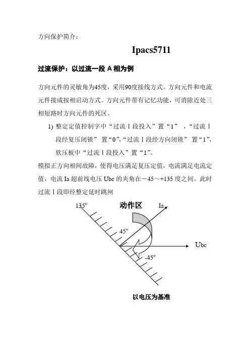
方向保护简介:Ipacs5711过流保护:以过流一段A相为例方向元件的灵敏角为45度,采用90度接线方式。
方向元件和电流元件接成按相启动方式。
方向元件带有记忆功能,可消除近处三相短路时方向元件的死区。
1)整定定值控制字中“过流Ⅰ段投入”置“1”,“过流Ⅰ段经复压闭锁”置“0”,“过流Ⅰ段经方向闭锁”置“1”,软压板中“过流Ⅰ段投入”置“1”。
模拟正方向相间故障,使得电压满足复压定值,电流满足电流定值,电流Ia超前线电压Ubc的夹角在-45~+135度之间。
此时过流Ⅰ段即经整定延时跳闸135º动作区Ia45ºU bc-45º以电压为基准在继保测试仪上加量:Ua=Uc=Ib=Ic=0 角度为0ºUb=57V 角度为0ºIa=6A (过流保护定值为5A),角度从-46度开始加量到136度截止。
如上图所示,动作区为-45º~+135ºB、C相方向保护做法一样。
知识补充:过流保护功率方向继电器90º接线如下表所示,保护处于送电侧,系统正常运行,cosφ=1时,3个功率方向继电器的测量的ψ角度均为90º,该接线因此而命名。
功率方向继电器电流电压KWa Ìa ÙbcKWb Ìb ÙcaKWc Ìc Ùab按相启动方式:A、B、C三相电流继电器与功率方向继电器先串后并KAa KWaKAb KWbKAc KWcIpacs5742过流保护:以过流一段A相为例方向元件采用正序电压极化,方向元件和电流元件采用按相起动方式。
方向元件带有记忆功能以消除近处三相短路时方向元件的死区。
方向元件灵敏角为45 度或225 度,可以通过控制字整定选择。
接入TA 的正极性端在母线侧。
(1)投入“投复压过流”硬压板(2)投入“过流Ⅰ段投入”软压板(3)定值中“过流Ⅰ段投入”控制字置“1”,“复压闭锁过流Ⅰ段”控制字置“0”,“方向闭锁过流Ⅰ段”控制字置“1”,“过流保护方向指向”,方向元件灵敏角为225 度;电流超前电压的夹角在135~315度之间。
iPACS-5761简易母差保护装置技术说明书版本:V2.04江苏金智科技股份有限公司iPACS-5761简易母差保护装置技术说明书(V2.04)目录1 概述 (1)1.1 应用范围 (1)1.2 保护配置和功能 (1)1.2.1 保护配置 (1)1.2.2 保护信息功能 (1)2 技术参数 (2)2.1 机械及环境参数 (2)2.1.1 工作环境 (2)2.1.2 机械性能 (2)2.2 电气参数 (2)2.2.1 额定数据 (2)2.2.2 功率消耗 (2)2.2.3 过载能力 (2)2.3 主要技术指标 (2)2.3.1 过流保护 (2)2.3.2 遥信开入 (3)2.3.3电磁兼容 (3)2.3.4 绝缘试验 (3)2.3.5 输出接点容量 (3)3 软件工作原理 (4)3.1 保护程序结构 (4)3.2 装置起动元件 (4)3.3 过流保护 (5)3.4 装置自检 (6)3.5 装置运行告警 (6)3.5.1 TV断线 (6)3.5.2 TA断线 (6)3.6 对时功能 (7)3.7 逻辑框图 (7)4 定值内容及整定说明 (8)4.1 系统定值 (8)4.2 保护定值 (8)4.3 通讯参数 (9)4.4 软压板 (9)5装置接线端子与说明 (10)5.1 模拟量输入 (10)5.2 背板接线说明 (10)5.3 装置结构及安装参考尺寸 (12)1 概述1.1 应用范围iPACS-5761适用于35kV以下电压等级的非直接接地系统或小电阻接地系统中的母线保护,可组屏安装,也可在开关柜就地安装。
1.2 保护配置和功能1.2.1 保护配置1)三段可经复压闭锁的过流保护。
1.2.2 保护信息功能1)装置描述的远方查看。
2)系统定值的远方查看。
3)保护定值和区号的远方查看、修改功能。
4)软压板状态的远方查看、投退、遥控功能。
5)装置保护开入状态的远方查看。
6)装置运行状态(包括保护动作元件的状态、运行告警和装置自检信息)的远方查看。
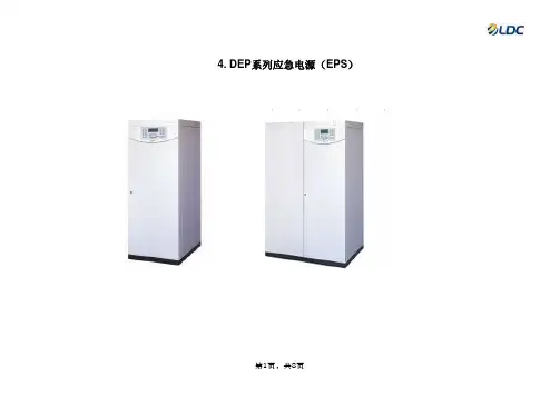
4. DEP系列应急电源(EPS)一、EPS架构示意图(仅标示核心部件)二、产品原理:当市电正常时,由市电经过互投装置给负载供电,同时充电器给备用电池进行智能充电。
当市电断电或超过正常电压的+-25%时,由CPU提供逆变信号,启动逆变电源,同时互投装置将切换至逆变电源输出,继续提供正弦波交流电,当市电电压正常30S后,应急电源将自动恢复电网供电。
三、产品用途及适用范围:EPS应急电源,专门为消防设备和照明用电等而设计。
它是建筑物内出现紧急情况下,为疏散照明提供集中供电的应急用电源设备。
产品适用范围:◎消防:电梯、喷淋泵、卷帘门等◎高层建筑:楼道照明、水泵、风机等◎金融系统设备:证券交易大屏、监控装置、金融机具、金库◎军用雷达、车载移动电话、人防通道、地下设施◎政府机关、大型超市、商场、学校、广场、车站、公园◎体育场馆、会展中心等重要场所的应急照明四、EPS产品特点:■采用先进的DSP控制,使产品更可靠、更稳定,实现了产品的数字化控制;■全中文大屏幕,流程指示,状态指示,实时显示EPS的工作状态及运行参数,直观、方便,使用户操作更为简单;■完善的电池管理功能,具有自动均充转浮充转换、定期电池维护、总电压显示以及电池故障报警等功能,使EPS蓄电池使用寿命更长;■采用工频变压器隔离输出,具有负载适应能力强、抗冲击性好、可靠性高等特点,且适合任意性质负载供电;■具有RS485、RS232(选件)、MODBUS通讯协议,使产品能够实现智能化;■具备干接点远程监控、控制功能,使人在突发事故时可远距离控制设备,避免在不适合人生活的环境中操作造成额外的损伤,也■智能风机控制系统可以根据负载的不同功率控制风机的转速,在节能的同时使用寿命更长;■自动切换,可实现无人值守,EPS电源与电网相互切换时间小于0.1秒,满足所有应急供电要求;■利用市电旁路,逆变器后备工作供电方式,使在市电状态下效率>99%为用户节省了电能,非应急供电时,基本无损耗;■具备两路互投功能,检测主电及备电有、无自动切换和互锁。
576芯落地式光缆交接箱使用安装手册上海亨通宏普通信技术有限公司●产品用途:主要用于通信光缆至各光交接点的连接,分配和调度。
本产品提供安全可靠,灵活机动的光纤线路管理。
适用于各种光通信网络。
●光缆型式:带状或非带状光缆进入数量:≤24条进入方向:箱体底部光缆接续容量:576芯尾纤规格:非带状尾纤长度为2000mm,带状尾纤长度为裸光纤部分1000mm+扇形单芯部分1000mm●光适配器规格:LC/SL/FC●操作面:双面●外形尺寸:1460(高)×750mm(宽)×570mm(深)●交接箱净重:约100Kg1.主要光电技术参数●连接器衰减(插入、互换、重复)≤0.3dB。
●回波损耗:APC 型≥60dB,UPC 型≥50dB,PC 型≥40dB。
●连接器插拔耐久性寿命>1000 次。
●高压防护接地装置:●绝缘电阻:≥2X10⁴ MΩ/500V(直流)。
●耐电压:≥3000V(直流)/1min,不击穿、无飞弧。
●接地线截面积:>6mm2,接地处有明显的接地标志。
主要机械性能参数●箱体防护等级:IP65 级。
●产品采用下进缆方式,防水性好。
●光路标识清晰,有效避免维护过程中拆卸可能导致的混乱。
●全程曲率半径控制,保证在任何位置光纤的曲率半径大于40mm。
●箱体顶端表面能承受的垂直压力:>1000N,门打开后最外端能承受的垂直压力:>200N。
●阻燃:符合GB5169.7 实验A 要求。
2.结构特征产品组成●室外落地式光缆交接箱由箱体、钣金件、熔接配线一体化模块、直熔模块、光缆固定开剥保护装置及附件组成。
工时可以取下熔配模块,直通熔接区域在模块区底部。
●箱体采用 SMC 材料,隔热性能良好,高性能橡胶密封条,有效防雨防尘,全方位适应户外环境。
●箱体内部金工件耐腐蚀,防老化,强度高,使用寿命长。
●能同时满足带状光缆和非带状光缆的使用需求。
●有可靠的光缆固定、开剥、接地、保护装置。
●全模块化设计,可根据客户要求灵活组装。
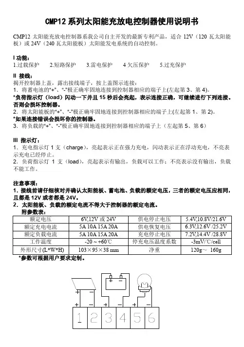
CMP12系列太阳能充放电控制器使用说明书CMP12太阳能充放电控制器系我公司自主开发的最新专利产品,适合12V(120瓦太阳能板)或24V(240瓦太阳能板)太阳能发电系统的自动控制。
I功能:1.过载保护2.短路保护3.雷电保护4欠压保护 5.过充保护II 接线:揭开控制器上盖,露出接线端子,按上盖图示连接:1.将蓄电池的“+”、“-”极正确牢固地连接到控制器相应的端子上(左起第3、第4)。
*负荷指示灯(load)闪动一下并且15秒后会亮起,表示连接正确,可继续进行下列连接。
否则会损坏控制器。
2.将太阳能板的“+”、“-”极正确牢固地连接到控制器相应的端子上(左起第1、第2)。
*如果连接错误会损坏你的控制器。
3.将负载的“+”、“-”极正确牢固地连接到控制器相应的端子上(左起第5、第6)III 指示灯:1.充电指示灯1支(charge),亮起表示正在强力充电,闪动表示正在浮动充电,不亮表示充电已经停止。
2.负荷指示灯1支(load),亮起表示有输出,负载可以工作;不亮表示没有输出,负载不能工作。
注意事项:1.接线前请仔细核对并确认太阳能板、蓄电池、负载的额定电压,三者的额定电压应相同,且都是12V或者都是24V。
2.太阳能板、负载的额定电流不得大于控制器的额定电流。
CMP12SOLAR CHARGE CONTROLLERUser’s manualThe product is used to control Solar Panel and battery in Solar System automatically. Here is the Solar Panel Configuration list with different rated voltage (12V and 24V).Ⅰ. FUCTION:1. Over-load protection2. Short circuit protection3. lightning protection4. Under-voltage protection5. Over-charging protectionⅡ. CONNECTION (AS INDICATED IN DIAGRAM):Open the top cover of controller and connect the wire with terminals follow the diagram on the top cover of it.1. Connect the “+”,“-” Poles of the battery to the corresponding ports of controller (the thirdand the fourth one from left).* The subsequent operation can be processed if only if load indicator (mark: load) flickers once and starts lighting after 15 seconds. Otherwise, the subsequent operation will damage the controller.2. Connect the “+”, “-” poles of the solar panel to the corresponding ports of controller (thefirst and the second one from left).*If a connection error can damage your controller.3. Connect the “+”,“-” poles of the load to the corresponding ports of controller (the fifth andthe sixth one from left).Ⅲ. INDICATOR LED1. Charge LED is used to indicate the charging status of battery. Lighting is in-charging mode,flashing is floating charge mode. LED turn off means charging stopped.2. There is output and load can work if the Load LED is lighting. There isn’t output and theload cannot work if Load LED off.Notice:1. Please make sure the rated voltage of solar panels, batteries the loads are the same. Allof them should be 6V,12V or 24V.2. The rated current of solar panels and load must be less than the rated current ofcontroller.Parameters may customized by customers.。
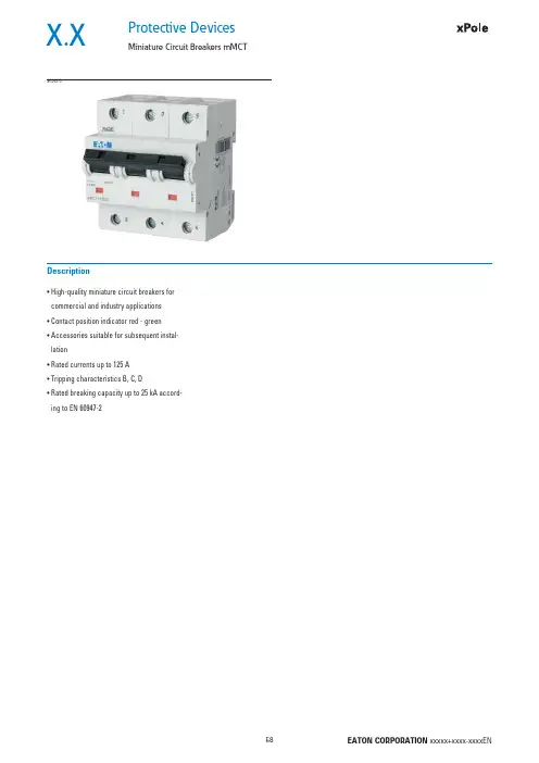
Protective DevicesMiniature Circuit Breakers mMCTX.X• H igh-quality miniature circuit breakers for commercial and industry applications • C ontact position indicator red - green • A ccessories suitable for subsequent instal-lation• R ated currents up to 125 A • T ripping characteristics B, C, D• R ated breaking capacity up to 25 kA accord-ing to EN 60947-2DescriptionSG04210X.X Protective DevicesMiniature Circuit Breakers mMCTRated current I n (A)TypeDesignationArticle No.Units perpackage25 kA, Characteristic BSG0401020mMCT-B20/11525621225mMCT-B25/11526341232mMCT-B32/11525631240mMCT-B40/11525641250mMCT-B50/11525651263mMCT-B63/11526351280mMCT-B80/112964612100mMCT-B100/112964712125mMCT-B125/1129648121-poleSG0541020mMCT-B20/2152704625mMCT-B25/2152636632mMCT-B32/2152705640mMCT-B40/2152706650mMCT-B50/2152707663mMCT-B63/2152637680mMCT-B80/21296546100mMCT-B100/21296556125mMCT-B125/212965662-poleSG0421020mMCT-B20/3152716425mMCT-B25/3152638432mMCT-B32/3152717440mMCT-B40/3152718450mMCT-B50/3152719463mMCT-B63/3152639480mMCT-B80/31296624100mMCT-B100/31296634125mMCT-B125/312966443-poleSG0561020mMCT-B20/3N152740325mMCT-B25/3N153012332mMCT-B32/3N152741340mMCT-B40/3N152742350mMCT-B50/3N152743363mMCT-B63/3N153013380mMCT-B80/3N1296783100mMCT-B100/3N1296793125mMCT-B125/3N12968033+N-poleSG0551020mMCT-B20/4152728325mMCT-B25/4153010332mMCT-B32/4152729340mMCT-B40/4152730350mMCT-B50/4152731363mMCT-B63/4153011380mMCT-B80/412967034-poleProtective DevicesMiniature Circuit Breakers mMCT X.XRated current I n (A)TypeDesignationArticle No.Units perpackage25 kA, Characteristic CSG0401020mMCT-C20/11525661225mMCT-C25/11580591232mMCT-C32/11525671240mMCT-C40/11525681250mMCT-C50/11525691263mMCT-C63/11583101280mMCT-C80/112964912100mMCT-C100/112965012125mMCT-C125/1129651121-poleSG0541020mMCT-C20/2152708625mMCT-C25/2158313632mMCT-C32/2152709640mMCT-C40/2152710650mMCT-C50/2152711663mMCT-C63/2158314680mMCT-C80/21296576100mMCT-C100/21296586125mMCT-C125/212965962-poleSG0421020mMCT-C20/3152720425mMCT-C25/3158317432mMCT-C32/3152721440mMCT-C40/3152722450mMCT-C50/3152723463mMCT-C63/3158318480mMCT-C80/31296654100mMCT-C100/31296664125mMCT-C125/312966743-poleSG0561020mMCT-C20/3N152744325mMCT-C25/3N158325332mMCT-C32/3N152745340mMCT-C40/3N152746350mMCT-C50/3N152747363mMCT-C63/3N158326380mMCT-C80/3N1296813100mMCT-C100/3N1296823125mMCT-C125/3N12968333+N-poleSG0551020mMCT-C20/4152732325mMCT-C25/4158321332mMCT-C32/4152733340mMCT-C40/4152734350mMCT-C50/4152735363mMCT-C63/4158322380mMCT-C80/412967334-poleX.X Protective DevicesMiniature Circuit Breakers mMCTRated current I n (A)TypeDesignationArticle No.Units perpackage25 kA, Characteristic DSG0401020mMCT-D20/11527001225mMCT-D25/11583111232mMCT-D32/11527011240mMCT-D40/11527021250mMCT-D50/11527031263mMCT-D63/11583121280mMCT-D80/112965212100mMCT-D100/1129653121-poleSG0541020mMCT-D20/2152712625mMCT-D25/2158315632mMCT-D32/2152713640mMCT-D40/2152714650mMCT-D50/2152715663mMCT-D63/2158316680mMCT-D80/21296606100mMCT-D100/212966162-poleSG0421020mMCT-D20/3152724425mMCT-D25/3158319432mMCT-D32/3152725440mMCT-D40/3152726450mMCT-D50/3152727463mMCT-D63/3158320480mMCT-D80/31296684100mMCT-D100/312966943-poleSG0561020mMCT-D20/3N152748325mMCT-D25/3N158327332mMCT-D32/3N152749340mMCT-D40/3N152750350mMCT-D50/3N152751363mMCT-D63/3N158328380mMCT-D80/3N1296843100mMCT-D100/3N12968533+N-poleSG0551020mMCT-D20/4152736325mMCT-D25/4158323332mMCT-D32/4152737340mMCT-D40/4152738350mMCT-D50/4152739363mMCT-D63/4158324380mMCT-D80/412967634-poleX.XProtective DevicesMiniature Circuit Breakers mMCT - T echnical DataSpecifi cations | Miniature Circuit Breakers mMCTDescription• Independent switching contacts• W ith isolator function, meets the requirements of insulation co-ordination,distance between contacts ≥ 4 mm, for secure isolationAccessories:Auxiliary switch for subsequent installation (0.5 MU)Z-LHK248440Shunt trip release subsequent installation (1.5 MU)Z-LHASA/230248442Z-LHASA/24248441 Switching interlock LH-SPL285752Technical DatamMCTElectricalEN 60947-2Design according toCurrent test marks as printed onto the deviceRated voltage U n AC: 230/400 VDC: 60 V (per pole, max. 2 poles)Ultimate short circuit breaking capacity according to IEC/EN 60947-2Characteristic B, C I n = 20-63 A: 25 kAI n = 80-100 A: 20 kAI n = 125 A: 15 kACharacteristic D I n = 20-63 A: 25 kAI n = 80 A: 20 kAI n = 100 A: 15 kACharacteristic in accordance with B, C, DBack-up fuse max. 200 A gLRated insulation voltage U i440 VPeak withstand voltage U imp 4 kVSelectivity class in accordance with class 3Endurance≥ 20,000 switching operationsMechanicalFrame size45 mmDevice height90 mmDevice width27 mm (1.5MU) per poleMounting quick fastening with 2 lock-in positions on DIN rail IEC/EN 60715 Degree of protection IP20Degree of protection, built-in IP40Upper and lower terminals lift terminalsTerminal protection fi nger and hand touch safe, DGUV VS3, EN 50274Terminal capacity 2.5-50 mm2Connection diagrams4-pole1-pole 2-pole 3-pole 3+N-poleX.XProtective DevicesMiniature Circuit Breakers mMCT - T echnical DataDimensions (mm)Load CapacityDurchlassenergieMaximum let-through energy mMCT, Characteristic C, 1-poleMaximum let-through energy mMCT, Characteristic D, 1-poleLoad capacity in case of block installationEffect of ambient temperaturePermitted permanent load at ambient temperature T [°C] with n devices: I DL = I n K T (T)K N (N).Ambient temperature T [°C]L o a d c a p a c i t y K T [I /I n ]Number of devices (n) 1-poleL o a d c a p a c i t y f a c t o r KNL e t t h r o u g h e n e r g y I 2t [A 2 s e c ]Protective DevicesMiniature Circuit Breakers mMCT - T echnical DataX.XShort Circuit Selectivity mMCT towards D01, D02, D03 and NH size 00Selectivity towards back-up fuses D01, D02, D03••Selectivity towards back-up fuses NH size 00mMCT Rated current of the back-up fuse in A gL/gG I n [A]2535506380100Characteristic CCharacteristic D mMCT Rated current of the back-up fuse in A gL/gG I n [A]253540506380100125160200Characteristic CCharacteristic D mMCT Rated current of the back-up fuse in A gL/gG I n [A]2535506380100mMCT Rated current of the back-up fuse in A gL/gG I n [A]253540506380100125160200X.XProtective DevicesMiniature Circuit Breakers mMCT - T echnical DataShort Circuit Selectivity mMCT towards NZMIn case of short circuit, there is selectivity between the miniature circuit breakers mMCT and the upstream NZM up to the specifi ed values of the selectivity limit current I s [kA] (i. e. in case of short-circuit currents I ks under I s only the MCB will trip, in case of short circuit currents above this value both protective devices will respond). Overload and short-circuit release unit NZM at max. value.*) basically in accordance with EN 60898-1 D.5.2.bShort circuit selectivity Characteristic C towards NZM1*)Short circuit selectivity Characteristic D towards NZM1*)mMCT NZM...1-A gL/gG I n [A]40506380100125200.30.40.50.750.9 1.251) Selectivity limit current I sunder 0.5 kA2) S electivity limit current I s = rated breaking capacity I cn of the MCBDarker areas: no selectivitymMCT NZM...1-A gL/gG Short circuit selectivity Characteristic C towards NZM2*)Short circuit selectivity Characteristic D towards NZM2*)mMCTNZM...2-A gL/gG I n [A]40506380100125160200250200.30.40.50.750.9 1.25 1.8 2.5 3.5mMCT NZM...2-A gL/gG。
iPACS-5762D母联(分段)保护测控装置技术说明书版本:V1.00江苏金智科技股份有限公司目录1 概述 (1)1.1 应用范围 (1)1.2 保护配置和功能 (1)1.2.1 保护配置 (1)1.2.2 保护信息功能 (1)2 技术参数 (2)2.1 机械及环境参数 (2)2.1.1 工作环境 (2)2.1.2 机械性能 (2)2.2 电气参数 (2)2.2.1 额定数据 (2)2.3 主要技术指标 (2)2.3.1 充电过流保护 (2)2.3.2 充电零序过流保护 (2)2.3.3 电磁兼容 (2)2.3.4绝缘试验 (3)3 软件工作原理 (3)3.1 保护程序结构 (3)3.2 装置起动元件 (3)3.2.1 充电过流起动 (3)3.2.2充电零序过流起动 (4)3.3 充电过流保护 (4)3.4 充电零序电流保护 (4)3.5 装置自检 (4)3.6 装置运行告警 (4)3.6.1 CT断线 (4)3.6.2 SV总告警 (4)3.6.3 SV采样数据异常 (4)3.6.4 SV采样链路中断 (4)3.6.5 GOOSE总告警 (4)3.6.6 GOOSE数据异常 (5)3.6.7 GOOSE链路中断 (5)3.7 遥控、遥测、遥信功能 (5)3.8 对时功能 (5)3.9逻辑框图 (6)4 定值内容及整定说明 (7)4.1 设备参数定值 (7)4.2 装置参数 (7)4.3 保护定值 (7)4.4 通讯参数 (7)4.5 软压板 (8)5装置接线端子与说明 (9)5.1 各插件原理说明 (9)5.2.1 与电子互感器的连接 (10)5.2.2 与断路器的连接 (10)5.2.3 电源插件(DC) (11)5.2.4 CPU插件(CPU) (11)5.2.5 通信插件(COM) (11)1 概述1.1 应用范围iPACS-5762D充电保护测控装置可实现各电压等级、不同主接线方式(内桥、单母线、单母线分段及其他扩展方式)的分段(桥)开关或进线开关的充电保护和测控功能。
PST1210U非电量保护技术说明书范文国电南自标准号:GB/T14598.300-2022数字式非电量保护装置国电南京自动化股份有限公司GUODIANNANJINGAUTOMATIONCO.,LTD编写审核批准V:1.00国电南京自动化股份有限公司2022年11月安全声明为保证安全、正确、高效地使用装置,请务必阅读以下重要信息:1.装置的安装调试应由专业人员进行;3.装置上电前,应明确连线与正确示图相一致;4.装置应该可靠接地;5.装置施加的额定操作电压应该与铭牌上标记的一致;6.严禁无防护措施触摸电子器件,严禁带电插拔模件;7.接触装置端子,要防止电触击;8.如要拆装装置,必须保证断开所有地外部端子连接,或者切除所有输入激励量。
否则,触及装置内部的带电部分,将可能造成人身伤害;9.对装置进行测试时,应使用可靠的测试仪;10.装置的运行参数和保护定值同样重要,应准确设定才能保证装置功能的正常运行;11.改变当前保护定值组将不可避免地要改变装置的运行状况,在改变前应谨慎,并按规程作校验;12.装置操作密码为:99。
版本声明本说明书适用于PST1210U数字式非电量保护V1.00版本。
1.软件本说明书为PST1210U数字式非电量保护V1.00版本软件的说明书,其中包含非电量保护跳闸及信号等功能。
其保护功能可以满足500kV及以下电压等级的变压器、电抗器非电量保护要求。
2.硬件本装置采用POWERPC微处理器进行逻辑运算,总体运算速度快。
产品说明书版本修改记录表10987654321V1.00适用于国网标准的PST1210U技术说明书第1版正式归档。
V1.某某2022/3序号说明书版本号修改摘要软件版本号修改日期某本说明书可能会被修改,请注意核对实际产品与说明书的版本是否相符某2022年9月第1版第1次印刷目录安全声明版本声明1概述.............................................................. ....................11.1适用范围.............................................................. ................................................................ .......................11.2保护配置.............................................................. ................................................................ .......................11.3性能特点.............................................................. ................................................................ .......................12技术性能及指标.............................................................. ..........32.1额定电气参数.............................................................. ................................................................ ...............32.2主要技术性能及指标.............................................................. ................................................................ ..32.3环境大气条............................................错误!未定义书签。
Eaton PDG12G0125TFFJEaton Power Defense molded case circuit breaker, Globally Rated, Frame 1, Two Pole, 125A, 35kA/480V, T-M (Fxd-Fxd) TU, Standard Line and Load (PDG1X2T125)Eaton Power Defense molded case circuit breakerPDG12G0125TFFJ 78667921605776 mm 139.7 mm 50.8 mm 0.907 kg Eaton Selling Policy 25-000, one (1) year from the date of installation of theProduct or eighteen (18) months from thedate of shipment of the Product,whichever occurs first.RoHS Compliant CCC MarkedCSAUL 489IEC 60947-2Product NameCatalog Number UPCProduct Length/Depth Product Height Product Width Product Weight WarrantyCompliancesCertifications125 AComplete breaker 1Two-polePD1 Global Class A T-M (Fxd-Fxd) TU600 Vac600 VStandard Line and Load35 kAIC at 480 Vac 22 kAIC Icu @250 Vdc55 kAIC Icu/ 55 kAIC Ics/ 121 kAIC Icm @240V (IEC) 65 kAIC @240V (UL) 22 kAIC Icu @125 Vdc36 kAIC Icu/ 36 kAIC Ics/ 76 kAIC Icm @380-415V (IEC) 18 kAIC @600V (UL/CSA) 35 kAIC @480V (UL)Eaton Power Defense MCCB PDG12G0125TFFJ 3D drawing Consulting application guide - molded case circuit breakers Power Defense technical selling booklet Power Defense brochurePower Defense molded case circuit breaker selection poster Power Defense molded case circuit breakers - Frame 1 product aidAmperage Rating Circuit breaker frame type Frame Number of poles Circuit breaker type Class Trip Type Voltage rating Voltage rating - max TerminalsInterrupt rating Interrupt rating range 3D CAD drawing packageApplication notesBrochuresCatalogsMolded case circuit breakers catalogCertification reportsPDG1 CCC certificationEU Declaration of Conformity - Power Defense molded case circuit breakersPower Defense Declaration concerning California’s Proposition 65PDG1 UL authorizationPDG1 CSA certificationInstallation instructionsPower Defense Frame 1-2-3-4 IP door barrier assembly instructions -IL012278ENPower Defense Frame 1 UL global box terminal (steel) 125A 2P -IL012165EN H02Power Defense Frame 1 UL global handle block padlockable off only - IL012179ENPower Defense Frame 1 UL global interphase barrier - IL012176EN Power Defense Frame 1 UL global screw terminal end cap kit 125A 2P - IL012162ENPower Defense Frame 1 UL global handle block non padlockable -IL012177ENPower Defense Frame 1 UL global DIN rail adapter 2, 3, 4-pole -IL012185ENPower Defense Frame 1 UL Global variable depth rotary handle mech installation instructions - IL012308ENPower Defense Frame 1 UL global handle block padlockable -IL012178ENPower Defense Frame 1 UL global Padlockable Handle Lock Hasp -IL012225ENPower Defense Frame 1 Instructions - IL012152ENPower Defense Frame 1 UL global tunnel terminal (aluminum) 125A 2P - IL012166EN H02Power Defense Frame 1 UL global screw terminal end cap kit metric 125A 2P - IL012170ENPower Defense padlockable handle lock hasp top off only installation instructions - IL012226ENPower Defense Frame 1 UL global lock padlockable handle haspIL012180ENPower Defense Frame 1 UL global interphase barrier instructions -IL012313ENInstallation videosEaton Corporation plc Eaton House30 Pembroke Road Dublin 4, Ireland © 2023 Eaton. All Rights Reserved. Eaton is a registered trademark.All other trademarks areproperty of their respectiveowners./socialmediaPower Defense Frame 1 UL Global Aux, Alarm, ST and UVR Animated Instructions.rh Power Defense Frame 3 Variable Depth Rotary Handle Mechanism Installation How-To VideoPower Defense Frame 5 Trip Unit How-To Video Eaton Power Defense for superior arc flash safety Power Defense BreakersPower Defense Frame 2 Variable Depth Rotary Handle Mechanism Installation How-To VideoPower Defense molded case circuit breakers Power Defense Frame 6 Trip Unit How-To Video Eaton Specification Sheet - PDG12G0125TFFJ Power Defense time current curve Frame 1 - PDG1Single and double break MCCB performance revisited Safer by design: arc energy reduction techniques Molded case and low-voltage breaker healthMultimediaSpecifications and datasheetsTime/current curvesWhite papers。
iPACS-5791远动装置技术和使用说明书版本:V2.01江苏金智科技股份有限公司目录1. 概述 (1)2. 特点 (1)3. 硬件介绍 (2)3.1.硬件模块介绍 (2)3.2.硬件接线说明 (2)4. 软件功能 (5)5. 主要技术指标 (6)6. 结构视图及安装尺寸 (7)6.1.视图 (7)6.2.安装尺寸 (8)6.3.端子定义 (8)7. 菜单操作说明 (9)7.1.菜单结构 (9)7.2.菜单界面 (10)7.2.1. 首页界面 (10)7.2.2. 首页界面 (10)7.2.3. 主菜单 (11)7.2.4. 通讯状态菜单 (11)7.2.5. “实时数据” (11)7.2.6. “历史数据” (13)7.2.7. “参数设置” (13)7.2.8. 版本信息 (18)1.概述iPACS-5791远动装置作为变电站自动化系统中远动设备,是变电站内的智能设备和调度系统信息交互的桥梁。
在变电站自动化系统中,iPACS-5791对内通过各种通讯接口收集间隔层的保护、监控、电度、等智能设备的信息,对外通过网络、模拟或者数字通道将这些信息传送到调度;同时将调度的命令传递给站内的各智能设备,实现调度对变电站内智能设备的控制。
iPACS-5791对内可以提供多种通讯接口:以太网(10/100Base-TX、100Base-FX)、串口(RS-232/485/422)以及其它的现场总线接口。
同时在这些接口上可以运行多种规约(IEC 60870-5-103等)。
iPACS-5791对外可以提供多个以太网(10/100Base-TX、100Base-FX)、数字RS-232以及模拟通道接口。
同时可以适用多种协议(60870-5-101、IEC 60870-5-104、DNP3.0等)。
iPACS-5791包含了电气完全独立的双机。
双机之间(包括对内、对外接口)互作冗余备用。
2.特点●iPACS-5791采用自主研发的CPU主板,功能强大、外设丰富。