On9658中文资料(可见光照度传感器).
- 格式:doc
- 大小:94.00 KB
- 文档页数:5

On9658中⽂资料(可见光照度传感器)呈线性变化;z内置双敏感元,⾃动衰减近红外,光谱响应接近⼈眼函数曲线;z内置微信号CMOS放⼤器、⾼精度电压源和修正电路,输出电流⼤,⼯作电压范围宽,温度稳定性好;z可选光学纳⽶材料封装,可见光透过,紫外线截⽌、近红外相对衰减,增强了光学滤波效果;z符合欧盟RoHS指令,⽆铅、⽆镉; Fig.1 可见光照度传感器原理图■典型应⽤z背光调节:电视机、电脑显⽰器、LCD背光、⼿机、数码相机、MP4、PDA、GPS;z节能控制:室外⼴告机、感应照明器具、玩具;z仪器仪表:测量光照度的仪器及⼯业控制;z环保替代:替代传统光敏电阻、光敏⼆极管、光敏三极管;Ev=500Lux 1192Ev=1000Lux 1905 响应时间Tr - - 2 - µSTf - - 2 - µS ■光谱曲线Fig.3 波分多段环氧树脂(纳⽶胶)和普通环氧树脂光谱对⽐图备注:由于⼊射界⾯到芯⽚位置的深度不同,采⽤的封装材料不同,以及光源的误差,得到的数据会有所不同。
■测试电路Fig.4 光电流测试电路Fig.5 开光时间测试电路测试条件:环境温度25oC±3,下拉电阻R=1KΩ,电源电压Vdd=5V,光源采⽤普通⽩炽灯。
本资料所有指标均在此条件下测试。
■特性曲线A光源光照响应1.522.51002003004005006007008009001000照度(lux)(m A )Fig.6 A 光源光照响应输出电流曲线0.0040.0030.0020.001 01002003004005006007008009001000照度Fig.7 功耗随照度变化曲线静态电流&温度3.532.5)0102030405060708090100温度(°C)Fig.8 静态电流随温度变化的曲线0.0012.43.356789101112Vdd(V)静态电流Fig.9 静态电流随VDD变化的曲线功耗&温度0.00140.001605101520253035404550556065707580859095温度(℃)Fig.10 功耗随温度的变化曲线Fig.11 使⽤ON-9658传感器的⼆种光控典型电路。
基于环境检测的自动控制窗户系统研究作者:程良燕来源:《数字技术与应用》2013年第01期摘要:本文利用单片机技术和传感器技术相结合,设计出一种智能自动开、关窗系统。
通过检测室内一氧化碳和二氧化碳,室外噪声、光照、风速、雨量和温度等外界环境,实现自动控制窗户的开启和关闭。
关键词:单片机传感器自动控制中图分类号:TP393 文献标识码:A 文章编号:1007-9416(2013)01-0019-01窗户是调节室内环境的重要途径。
现有居室窗户的开启、关闭基本上依靠人工根据室内外环境状况手动操作完成。
但完全靠人工根据室内外空气状况、温度及天气状况而判定是否开、关窗户,容易导致一些意外情况的发生。
针对这类情况,本文研究一种以室内温度、气体成分及室外温度、风力、降雨因素为控制参数的智能式自动开窗系统。
对人们的日常家庭生活有重要的实用价值。
1 测量原理本设计采用多种感应传感器,将雨量、风速、二氧化碳、一氧化碳、温度、光照和噪声等各种外界环境信号转换为电信号,而后通过集成电路和合理的单片机控制电路,控制电流流经相应的通路,以电流的正向反向控制电动机的正反转,从而实现窗户的开和闭。
(图1)2 环境信号的采集和处理2.1 各种环境信号的采集选用功率消耗小,抗干扰性强,并且体积小、寿命长、稳定性较好的传感器。
可以选用各种传感器的型号有:一氧化碳传感器TGS5042、二氧化碳传感器TGS4161、噪声传感器BR-ZS1、光照传感器ON9658F、风速传感器FC-2A3、湿度传感器HIH-4000-003和温度传感器LM35CZ。
这些传感器输出模拟信号,具有良好的线性输出。
2.2 放大滤波电路针对不同的传感器输出的电流或电压信号,应用相应的电流放大电路或电压放大电路,来对各种电信号进行放大滤波处理。
本设计中,一氧化碳传感器TGS5042、噪声传感器BR-ZS1和光照传感器ON9658F输出电流信号,故后级接电流放大电路;二氧化碳传感器TGS4161、风速传感器FC-2A3、湿度传感器HIH-4000-003和温度传感器LM35CZ输出电压信号,故后级接电压放大电路。
SC7260BRS485接口带通讯功能光照度控制器产品使用手册文件版本: V23.6.25SC7260B采用工业通用标准RS485总线 MODBUS-RTU协议接口,方便接入PLC,DCS等各种仪表或系统,用于监测光照等状态量。
内部使用了较高精度的传感内核及相关器件,确保产品具有较高的可靠性与卓越的长期稳定性, 可定制RS232、RS485、CAN、4-20mA、DC0~5V\10V、ZIGBEE、Lora、WIFI、GPRS、NB-IOT等多种输出方式。
技术参数外形尺寸产品接线请在断电线的情况下,按图示方法进行接线,如果产品本身无引线,线芯颜色供参考。
典型应用应用方案发货清单RS485型:通讯协议产品使用RS485 MODBUS-RTU标准协议格式,所有操作或回复命令都为16进制数据。
设备出厂时默认设备地址为1,默认波特率为模块及非记录仪表:9600,8,n,1 或记录仪:115200,8,n,1 。
1. 读取数据( 功能码0x03)问询帧(十六进制),发送举例:查询1#设备1个数据,上位机发送命令:01 03 00 00 00 01 84 0A 。
倍率为100,则真实值为121/100=1.21,其它以此类推。
2. 常用数据地址表3 读取与修改设备地址(1)读取或查询设备地址若不知道当前设备地址、且总线上只有一个设备时,可以通过命令FA 03 00 66 00 01 71为设备地址的寄存器。
对于正确的查询命令,设备会响应,比如响应数据为:01 03 02 00 01 79 84,其格式解(2)更改设备地址效,此时用户需要同时将自己软件的查询命令做相应更改。
4 读取与修改波特率(1)读取波特率设备默认出厂波特率为9600,若需要更改,可根据下表及相应通讯协议进行更改操作。
比为38400;6为115200。
对于正确的查询命令,设备会响应,比如响应数据为:01 03 02 00 03 F8 45,其格式解(2)更改波特率比如将波特率从9600更改为38400,即将代码从3更改为5,则命令为:01 06 00 67 00 05备会失去响应,查询设备的波特率需做相应修改。
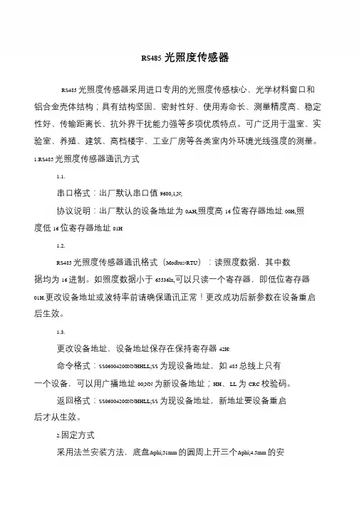
RS485光照度传感器
RS485 光照度传感器采用进口专用的光照度传感核心、光学材料窗口和铝合金壳体结构;具有结构坚固、密封性好、使用寿命长、测量精度高、稳定性好、传输距离长、抗外界干扰能力强等多项优质特点。
可广泛用于温室、实验室、养殖、建筑、高档楼宇、工业厂房等各类室内外环境光线强度的测量。
1.RS485 光照度传感器通讯方式
1.1.
串口格式:出厂默认串口值9600,1,N;
协议说明:出厂默认的设备地址为0AH,照度高16 位寄存器地址00H,照度低16 位寄存器地址01H
1.2.
RS485 光照度传感器通讯格式(Modbus-RTU):读照度数据,其中数据均为16 进制。
如照度数据小于65536lx,可以只读一个寄存器,即低位寄存器01H.更改设备地址或波特率前请确保通讯正常!更改成功后新参数在设备重启后生效。
1.3.
更改设备地址,设备地址保存在保持寄存器42H:
命令格式:SS06004200NNHHLL;SS 为现设备地址,如485 总线上只有一个设备,可以用广播地址00;NN 为新设备地址;HH、LL 为CRC 校验码。
返回格式:SS06004200NNHHLL;SS 为现设备地址,新地址要设备重启后才从生效。
2.固定方式
采用法兰安装方法,底盘φ51mm 的圆周上开三个φ4.5mm 的安。
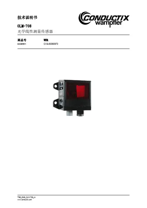
技术说明书OLM-708光学线性测量传感器商品号WNRCWA-600609703226597Conductix-Wampfler Automation GmbHHandelshof 16 A14478 PotsdamGermany电话: +49(0)331887344-0传真: +49(0)331887344-19邮件:**************************网址: 原文档的翻译2022年9月本技术说明中出现的使用名、商品名、商标等可能未作特殊标记,此时相应法律仍然适用。
© 2022 Conductix-Wampfler Automation GmbH技术说明书OLM-708目录目录目录 (3)1概述和安全 (5)1.1 用户须知 (5)1.2 提示标志 (6)1.3 责任范围 (7)1.4 版权保护 (7)1.5 符合性 (7)1.6 按照要求使用 (8)1.7 备件和维修 (8)1.8 保修 (9)1.9 客户服务 (9)1.10 改动和重组 (9)1.11 人员和资质 (10)1.12 废物处理指南和环保规定 (10)2产品说明 (11)2.1 使用范围/应用区域 (11)2.2 结构 (11)2.3 工作原理 (12)3安装, 连接, 调试 (13)3.1 条码条的铺设 (13)3.1.1 概述 (13)3.1.2 铺设计划指南 (14)3.1.3 剪裁的执行 (15)3.1.4 上升和下降段的铺设 (16)3.2 OLM-708的安装和对齐 (17)3.2.1 安装 (17)3.2.2 对齐 (18)3.3 OLM-708的电气连接 (19)3.4 调试 (19)技术说明书OLM-708目录4维护 (20)4.1 清洁 (20)4.2 保养 (20)5技术数据 (21)5.1 OLM-708的数据表 (21)5.2 OLM-708 尺寸图 (22)5.3 条码条的数据表 (23)5.4 条码条尺寸图 (23)5.5 条码条订购提示 (24)6故障排除 (25)技术说明书OLM-708概述和安全1概述和安全1.1用户须知本技术说明书包含这些型号的电源模块的技术信息:OLM-708本使用说明书描述了有关仪器的重要信息。
2013年重庆地区第7届“盛群杯”大学生单片机应用设计竞赛作品创意书********************************************************** ********************************************************** 作品编号:20130146基于HT66F50的智能花盆********************************************************** ********************************************************** 学校名称:重庆邮电大学院系名称:计算机科学与技术学院光电工程/国际半导体学院指导老师:周应华参赛学生1:冉敏参赛学生2:吕功建参赛学生3:史啸作品创意书一、摘要本作品主要采用HT66F50为核心采用来对花盆温度、湿度、光强、进行实时监控与调节的智能花盆系统。
在这个作品中我们采用数字式DS18B20作为温度传感器、土壤湿度计检测、可见光照度传感器On9658来实现对花盆的环境温度、土壤湿度、光照强度进行检测,并实时显示在液晶屏上。
通过键盘输入花盆中的植物在不同的时间段最适宜的生长条件(湿度、温度、光强),如若超过这一范围则会进行自动调控,如若经过调控后的花盆环境温湿度等依旧不达标,则通过报警的方式来提醒植物栽培者植物的生长处于不健康的状态,需要对其采取相应的措施。
本作品充分利用了HT66F50的A/D转换、时钟控制等功能,减少外部电路的扩展,以优良的软件设计来实现作品强大的功能。
在方案中我们的智能温度处理方法为采用电加热器升温,采用冷机进行降温处理;采用电磁阀滴灌加湿的方法来为植物提供水分,采用滴灌的方法的好处不仅是节约了水资源,而且有效的保证了植物生长期间不存在湿度过高的情况;LED灯组为植物补足光照,采用LED红蓝灯形成的灯组来为植物提供生长的光源。
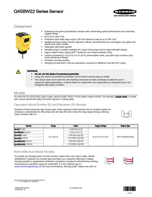
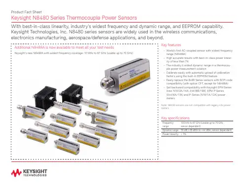
Datasheet•Advanced one-piece photoelectric sensors with outstanding optical performance and extremely rugged design•90 V AC to 250 V AC•Protected solid-state relay output; 300 mA maximum load at up to 250 V AC•Multiple sensing modes include: opposed, diffuse, retroreflective and convergent, plus glass and plastic fiber optic models •Selectable light/dark operate•Versatile plug-in modules available for output timing logic and/or signal strength display •Highly visible Power, Signal (AID ™ System 1), and Output indicator LEDs•Choice of prewired 2 m (6.5 ft) or 9 m (30 ft) unterminated cable, plus Mini-style or Micro-style quick-disconnect fittings •Versatile mounting options•Designed to withstand 1200 psi washdown; exceeds its NEMA 6P and IEC IP67 ratingWARNING:•Do not use this device for personnel protection•Using this device for personnel protection could result in serious injury or death.•This device does not include the self-checking redundant circuitry necessary to allow its use inpersonnel safety applications. A device failure or malfunction can cause either an energized (on) or de-energized (off) output condition.ModelsTo order the 9 m (30 ft) PVC cable model, add the suffix "W/30" to the cabled model number. For example, Q452E W/30. A model with a quick disconnect (QD) connector requires a mating cable.Opposed-Mode Emitter (E) and Receiver (R) ModelsBecause of their extremely high excess gain, these opposed-mode sensors are an excellent option for sensing in contaminated or dirty areas, and are also the best choice for long-range sensing. Sensingbeam: Infrared, 880 nmRetroreflective-Mode ModelsThe visible red sensing beam of these sensors makes them very easy to align. Model Q45BW22LP polarizes the emitted light and filters out unwanted reflections, makingsensing possible in applications otherwise considered unsuited to retroreflective sensing.Performance is specified using the model BRT-3 3-inch reflector (go to for more information). Sensing beam: Visible red, 680 nmQ45BW22 Series SensorOriginal Document 37209 Rev. G30 January 202037209Diffuse-Mode ModelsThese diffuse-mode models detect objects by sensing the reflection of their own emitted light.Ideal for use when the reflectivity and profile of the object to be sensed are sufficient to return alarge percentage of emitted light back to the sensor. Model Q45BW22DX is the first choice fordiffuse-mode applications when there are no background objects to falsely return light. Sensingbeam: Infrared, 880 nmConvergent-Mode ModelsThese sensors are ideal for reflective sensing of very small parts or profiles, and can accurately sensethe position of parts approaching from the side. Ignores all but highly reflective objects that are outsideof the sensing range. Sensing beam: Visible red, 680 nm - Tel: + 1 888 373 6767P/N 37209 Rev. GGlass Fiber-Optic ModelsThese models are an excellent choice for glass fiber optic applications where faster sensor response is not important. Their high excess gain means that opposed individual fibers can operate reliably in many very hostileenvironments. Also, special miniature bifurcated fiber optic assemblies with bundle sizes as small as 0.5 mm (0.020 in) dia. may be used successfully for diffuse-mode sensing when using sensor model Q45BW22F(Q). For more information on compatible glass fiber optics, go to .Plastic Fiber-Optic ModelsLower in cost than glass fiber optics, plastic fiber optics are ideal for use in situations whereenvironmental conditions allow (for example, low levels of acids, alkalis, and solvents). Most are easily cut to length in the field, and are available in a variety of sensing end styles. For more information on compatible plastic fiber optics, go to . Sensing beam: Visible red, 660 nmOverviewStatus indicator LEDs for power, signal, and output are clearly visible beneath a raised dome in the sensor’s transparent o-ring-sealed polycarbonate cover. Also located beneath the sensor’s o-ring-sealed cover are controls for light/dark operate selection and the sensitivity adjustment.•The power indicator (green) lights when power is applied to the sensor.•The signal indicator (red) lights when the sensor sees its modulated light source and pulses at a rate proportional to the strength of the received light signal; this is the AID ™ Alignment Indicating Device 2.•The output indicator (amber) lights when the sensor’s output is conducting. This indicator is especially useful when a timing logic module is used and signal and output conditions are not concurrent.1.LEDs•Green LED: Power on indicator •Red LED: Signal indicator•Amber LED: Output status indicator 2.Optional LED signal strength display 3.Optional timing adjustment 4.Optional timing adjustment 5.Light/dark operate switchP/N 37209 Rev. G - Tel: + 1 888 373 67673Wiring Diagram–+bn (1)bu (3)90–250 V AC1 = Brown 3 = Blue4 = Black1 = Red and black2 = Red and white3 = Red4 = GreenSpecificationsSupply Voltage and Current90 V AC to 250 V AC (50 to 60 Hz)Average current: 20 mAPeak current: 500 mA at 120 V AC, 750 mA at 250 V AC Supply Protection CircuitryProtected against transient voltagesOutput ConfigurationShort circuit/overload protected FET solid-state relayRepeatabilityOpposed mode: 0.25 millisecondsAll other sensing modes: 0.5 millisecondsResponse time and repeatability specifications are independent of signal strength.AdjustmentsLocated under the sensor’s transparent cover: Light/Dark Operate select switch; and multi-turn Sensitivity control (allows precise sensitivity setting—turn clockwise to increase gain). Optional logic and logic/display modules have adjustable timing functions. - Tel: + 1 888 373 6767P/N 37209 Rev. GOutput RatingContinuous current: 300 mA max. to 50 °C (derate to 200 mA at 70 °C, 5mA/°C)Inrush current: 3 A maximum for 100 milliseconds, 5 A maximum for 1millisecondOff-state leakage current: <100 microamps Saturation voltage: <3 V at 200 mA Output Protection CircuitryManually-resettable output latch-out trips in the event of an output overload or short circuit condition. The green Power LED flashes to indicate the latch-out. To reset the output, remove power to the sensor and load for 5seconds, then restore power.Output Response TimeOpposed mode: 2 milliseconds ON, 1 millisecond OFF All other sensing modes: 2 milliseconds ON/OFFNote: 100 millisecond delay on power-up.Output is non-conducting during this time.Required Overcurrent ProtectionWARNING: Electrical connections must bemade by qualified personnel in accordance with local and national electrical codes and regulations.Overcurrent protection is required to be provided by end product application per the supplied table.Overcurrent protection may be provided with external fusing or via Current Limiting, Class 2 Power Supply.Supply wiring leads < 24 AWG shall not be spliced.For additional product support, go to .ConstructionMolded reinforced thermoplastic polyester housing, o-ring-sealedtransparent polycarbonate cover, molded acrylic lenses, and stainless steel hardware. Q45s are designed to withstand 1200 psi washdown. The base of cabled models has a 1/2-in NPS integral internal conduit thread.IndicatorsIndicator LEDs are clearly visible beneath a raised transparent polycarbonate dome on top of the sensor.Power (green) LED: Lights whenever 90 V ac to 250 V ac power is applied,and flashes to indicate output overload or output short circuitSignal (red) AID ™ System LED: Lights whenever the sensor sees itsmodulated light source, and pulses at a rate proportional to the strength of the received light signalLoad (amber) LED: Lights whenever the output relay is energized Optional 7-element LED: Signal strength display module Environmental Rating NEMA 6P, IEC IP67ConnectionsPVC-jacketed 2 m (6.5 ft) or 9 m (30 ft) cables, or 3-pin Mini-style (“Q” suffix models) or 4-pin Micro-style (“Q1” suffix models) quick-disconnect (QD)fittings are available. QD cables are ordered separately.Operating Conditions–40 °C to +70 °C (–40 °F to +158 °F)90% at +50 °C maximum relative humidity (non-condensing)Application NotesOptional output timing modules are available.CertificationsDimensions2m (6.5') CableExternal thread (M30 x 1.5)hex nut suppliedQD ConnectorP/N 37209 Rev. G - Tel: + 1 888 373 67675Performance CurvesDiffuse-mode performance curves are based on a 90% reflectance white test card. - Tel: + 1 888 373 6767P/N 37209 Rev. Gwhite test card.Convergent mode performance curves are based on a 90% reflectanceP/N 37209 Rev. G - Tel: + 1 888 373 67677Plastic fiber optic Diffuse mode performance curves are based on a 90% reflectancewhite test card.AccessoriesCordsets - Tel: + 1 888 373 6767P/N 37209 Rev. GRetroreflective TargetsBanner offers a wide selection of high-quality retroreflective targets. See for complete information.Note: Polarized sensors require corner cube typeretroreflective targets. Non-polarized sensors may use any retroreflective target.BracketsOutput Timing Logic and Signal Strength Display ModulesQ45 sensors easily accept the addition of output timing logic and signal strength display functions. Display modules have a seven-element display that gives a more precise indication of excess gain than does the AID ™ system LED that is standard on Q45sensors. The modules listed below may be used with all Q45BW22 sensors. Refer to the module's datasheet for more information.P/N 37209 Rev. G - Tel: + 1 888 373 67679Banner Engineering Corp. Limited WarrantyBanner Engineering Corp. warrants its products to be free from defects in material and workmanship for one year following the date of shipment. Banner Engineering Corp. will repair or replace, free of charge, any product of its manufacture which, at the time it is returned to the factory, is found to have been defective during the warranty period. This warranty does not cover damage or liability for misuse, abuse, or the improper application or installation of the Banner product.THIS LIMITED WARRANTY IS EXCLUSIVE AND IN LIEU OF ALL OTHER WARRANTIES WHETHER EXPRESS OR IMPLIED (INCLUDING, WITHOUT LIMITATION, ANY WARRANTY OF MERCHANTABILITY OR FITNESS FOR A PARTICULAR PURPOSE), AND WHETHER ARISING UNDER COURSE OF PERFORMANCE, COURSE OF DEALING OR TRADE USAGE. This Warranty is exclusive and limited to repair or, at the discretion of Banner Engineering Corp., replacement. IN NO EVENT SHALL BANNER ENGINEERING CORP. BE LIABLE TO BUYER OR ANY OTHER PERSON OR ENTITY FOR ANY EXTRA COSTS, EXPENSES, LOSSES, LOSS OF PROFITS, OR ANY INCIDENTAL, CONSEQUENTIAL OR SPECIAL DAMAGES RESULTING FROM ANY PRODUCT DEFECT OR FROM THE USE OR INABILITY TO USE THE PRODUCT, WHETHER ARISING IN CONTRACT OR WARRANTY, STATUTE, TORT, STRICT LIABILITY, NEGLIGENCE, OR OTHERWISE.Banner Engineering Corp. reserves the right to change, modify or improve the design of the product without assuming any obligations or liabilities relating to any product previously manufactured by Banner Engineering Corp. Any misuse, abuse, or improper application or installation of this product or use of the product for personal protection applications when the product is identified as not intended for such purposes will void the product warranty. Any modifications to this product without prior express approval by Banner Engineering Corp will void the product warranties. All specifications published in this document are subject to change; Banner reserves the right to modify product specifications or update documentation at any time. Specifications and product information in English supersede that which is provided in any other language. For the most recent version of any documentation, refer to: .For patent information, see /patents.© Banner Engineering Corp. All rights reserved。
2THLxx可调恒流三极管系列产品可调恒流三极管2THLxx(CRT)作为第二代半导体恒流器件,是一种能为LED 或其他器件在电源电压变化时提供恒定电流的三端半导体器件,它和第一代产品CRD的应用是兼容的。
它利用一个可调整端,通过外部元件在一定范围内连续调节其输出电流,实现简单可靠的恒流源或最大峰值电流限制电路,即使出现电源电压供应不稳定或是负载电阻变化很大的情况,都能确保供电电流恒定。
该器件具有外围电路非常简单、输出电流可调、使用及其方便等特点,尤其适用于可调光LED 照明、动态LCD 背光、汽车电子、通信电路、手持设备、仪器仪表和微型机器等场合。
如果不用可调整端(空),和第一代产品CRD的使用完全相同。
■电气特性Fig.1 CRT可调恒流三极管电路标示图2THL060 8 2.0-69≤3.5 min0.8I H 6 max 1.157* 25 50 60 -(0.1-0.15)2DTL070 8 2.0-75≤3.5 min0.8I H 6 max 1.157*20 50 60 -(0.1-0.15)2DTL08082.0-85≤3.5min0.8I H6max 1.157*205060-(0.1-0.15)参数测试标准:I H ---- 恒定电流值,测试条件 Vs=5V;V K ---- 起始恒流电压,测试条件:测试电流 H K I I 8.0=; Z D ---- 动态阻抗,测试条件:V V S 10=; V R ---- 反向耐压,测试条件:nA I R 50=;K C ---- 控制电流比,测试条件:H P C I I K /=;时对应的电流是电压为E P V I ; T r ---- 脉冲上升时间; T f ---- 脉冲下降时间; I R ---- 反向漏电流 50nA;■产品系列、封装、最大额定值 :说明:1. 最大功耗P max 随型号、封装规格、散热条件会有所改变;2. 工作温度范围:-30~+150 ℃3. 存储温度:-40~+150 ℃4. 焊接温度:260 ℃5. 不带整流特性■ 产品测试电路Fig.2 恒流三极管测试电路原理注:E为测试电源,RK、RZ为可调电阻,mA为电流表,Vbo为整流二极管D二端的电压表,V为电压表, CRT为2THLxx可调恒流三极管。
一种日光温室自动监控系统王春萌;张大鹏【摘要】设计了一种以STR912为核心的的日光温室监控系统,同时选择了相关的温湿度、光照以及CO2传感器,并设计了相关的通信网络,并且使用了嵌入式操作系统FreeRtos.【期刊名称】《农业网络信息》【年(卷),期】2010(000)001【总页数】3页(P32-33,41)【关键词】日光温室;STR912;传感器;FreeRtos【作者】王春萌;张大鹏【作者单位】辽宁省农业科学院,辽宁,沈阳,110161;沈阳农业大学信息与电气工程学院,辽宁,沈阳,110866【正文语种】中文【中图分类】S126随着日光温室大棚的广泛应用,对环境控制的要求越来越高。
当前很多日光温室大棚采用人工监控,但是其所能达到的控制精度有限。
也有一部分日光温室使用了以单片机为核心的监控系统,但是受单片机性能的限制,难以完成日趋复杂的监控任务。
以下将介绍一种以ST公司的STR912为中央处理器,包括环境传感器、通信总线和执行机构所组成的日光温室监控系统。
1 控制系统总体结构1.1 系统总体结构监控系统如图1所示,整个系统既包括温湿度传感器、CO2传感器、光照传感器等,也包括中央控制台和485总线。
中央控制台以STR912为核心,包括人机界面(按键、液晶显示模块)、用户数据存储单元和控制执行机构的控制电路。
485总线负责把中央控制台和传感器连接到一起。
1.2 STR912介绍STR912是ST公司推出的基于ARM966E-S内核的微处理器,内核时钟可达96MHz,具有较强的处理能力,片上有544KB的Flash和96KB的SRAM,可以运行规模较大的程序,也适合移植一些嵌入式操作系统。
该处理器是工业级芯片,性能稳定、抗干扰能力强,可以适应复杂的应用环境且具有丰富的片上外设资源,本系统主要使用的是UART、SPI和ENET。
该处理器具有80个可用IO接口,可以支持较多的执行机构而无需其他扩展IO接口的芯片。
光照度传感器说明书适用型号:LH-LR2000修订记录:目录1.产品介绍 (2)2.规格参数 (2)3.产品尺寸 (3)4.485通信协议与数据格式 (3)4.1.通讯基本参数 (3)4.2.数据帧格式定义 (3)4.3.寄存器地址 (4)4.4.参数读取 (5)5.模拟量协议 (6)6.电气接线 (6)7.售后服务 (7)7.1.售后服务承诺 (7)7.2.免责声明 (8)7.3.联系方式 (8)1.产品介绍该变送器广泛适用于农业大棚、花卉培养等需要光照度监测的场合。
传感器内部的输入电源、感应探头、信号输出三部分完全隔离。
安全可靠,外观美观,安装方便。
2.规格参数3.产品尺寸图3.14.485通信协议与数据格式4.1.通讯基本参数4.2.数据帧格式定义采用Modbus-RTU 通询规约,格式如下:地址码=1字节功能码=1字节数据区=N字节错误校验=16位CRC码结束结构>=4字节的时间地址码:为设备的地址,在通询网络中是唯一的。
功能码:主机所发指令功能提示。
数据区:数据区是具体通询数区,注意16bits数据高字节在前。
CRC码:二字节的校验码。
地址码功能码寄存器起始地址寄存器长度校验码低位校验码高位问询1字节1字节2字节2字节1字节1字节地址码功能码有效字节数数据区校验码低位校验码高位应答1字节1字节1字节2字节1字节1字节4.3.寄存器地址4.4.参数读取(1)例:读取设备地址为01的传感器光照度地址码功能码起始地址数据值校验码低位校验码高位问询0x010x030x00,0x070x00,0x020x750xCA地址码功能码字节数数据值校验码低位校验码高位应答0x010x030x040x000x00,0x060xF60x7A0x31注释:光照度计算说明:000006F6H(十六进制)=1782=>光照度=1782Lux(2)例:查询设备地址、波特率地址码功能码起始地址数据值CRC低位CRC高位问询0x010x030x01,0x000x00,0x020xC50xF7应答地址码功能码有效字节数设备地址波特率CRC 低位CRC 高位0x010x030x040x00,0x010x00,0x030xEB0xF2读出设备地址为1;波特率为9600。
图1 照度计UV
传感器
照度计UV 传感器是为照度计RM12、RM21以及剂量控制仪UV-MAT 配置的测量UV 照射的探头。
根据眼睛对可见光的灵敏度曲线V (λ)(VISL ),它测量蓝光(VISB )或蓝-绿光(VISBG )的照度。
具有余弦校正功能的内置漫射器在非垂直照射中是非常必要的。
传感器根据PTB 标准而精确地校准。
传感器可以被制作成具有不同测量范围和符合IP65标准的防水类型,整合在内部的电子系统发生的信号电压通过封闭线路低噪声地传到照度计。
照度计UV 传感器
技术指标
测量范围 200mW/cm 2 (UV A/C ) 20 mW/cm 2 (UVB ) 分辨率 0.1 mW/cm 2 (UV A/C )
0.01 mW/cm 2 (UVB )
光谱范围 UVC 200-280nm
UVB 280-315nm UV A 315-400nm
工作电压 +/-5V 信号电压 0-2V 工作温度 0-40℃ 储藏温度 -10-40℃ 湿度 <80%
非冷凝
电缆 5股,2m 长
大小 Φ40,H 32mm
IP65:Φ50,H 47mm 重量 150g ,IP65:280g
图2 光谱灵敏度
货号
RM 传感器UVC 811040 RM 传感器UVB
811042 RM 传感器UV A 811090 RM 传感器UVC IP65 811240 RM 传感器UV A IP65 811290。
RS485光照度传感器
RS485光照度传感器
RS485 光照度传感器采⽤进⼝专⽤的光照度传感核⼼、光学材料窗⼝和铝合⾦壳体结构;具有结构坚固、密封性好、使⽤寿命长、测量精度⾼、稳定性好、传输距离长、抗外界⼲扰能⼒强等多项优质特点。
可⼴泛⽤于温室、实验室、养殖、建筑、⾼档楼宇、⼯业⼚房等各类室内外环境光线强度的测量。
1.RS485 光照度传感器通讯⽅式
1.1.
串⼝格式:出⼚默认串⼝值9600,1,N;
协议说明:出⼚默认的设备地址为0AH,照度⾼16 位寄存器地址00H,照度低16 位寄存器地址01H
1.2.
RS485 光照度传感器通讯格式(Modbus-RTU):读照度数据,其中数据均为16 进制。
如照度数据⼩于65536lx,可以只读⼀个寄存器,即低位寄存器01H.更改设备地址或波特率前请确保通讯正常!更改成功后新参数在设备重启后⽣效。
1.3.
更改设备地址,设备地址保存在保持寄存器42H:
命令格式:SS06004200NNHHLL;SS 为现设备地址,如485 总线上只有⼀个设备,可以⽤⼴播地址00;NN 为新设备地址;HH、LL 为CRC 校验码。
返回格式:SS06004200NNHHLL;SS 为现设备地址,新地址要设备重启后才从⽣效。
2.固定⽅式
采⽤法兰安装⽅法,底盘φ51mm 的圆周上开三个φ4.5mm 的安。
摘要随着互联网技术带动下的物联网的发展,智能家居逐渐开始迅猛发展。
照明作为家庭用电中的重要部分,智能照明也拥有广阔的发展前景。
而且随着人们对能源节约的越来越深入人心的认识,设计一种可以随着光照强度的变化来调节自身亮度的照明设备显得很有必要。
针对这一问题,本设计采用光照传感器模块采集环境光照强度,然后利用STC89C51单片机对灯光亮度进行控制,完成了光照强度的实时检测与显示,同时可对灯光进行相应的亮度调节,完成了各功能模块的硬件电路设计和软件程序编写,最后用Proteus进行了模拟仿真。
仿真结果表明该设计实现了光照强度的实时检测与显示并能对灯光亮度进行适当调节。
关键词:智能照明;光照强度检测;STC89C51;灯光自动控制;AbstractWith the development of Internet technology, the smart home is beginning to develop rapidly.As an important part of the household,intelligent illumination also has a huge development prospect.And as the understanding of energy saving is deeply rooted in people’s mind, designing a kind of light which can change its light intensity with the surrounding is very necessary.In order to solve this problem, this design uses the light sensor module to collect environmental light intensity and then use STC89C51 microcontroller to control the light pleted the real-time detection and display for the light intensity, and to adjust the brightness of the lighting accordingly a system of the design of the hardware system and software program. After the simulation with the Proteus. The simulation results show that the design realizes the real-time detection and display of the light intensity and can adjust the brightness of the light.Keywords:Intelligent lighting;Light intensity test;STC89C51;Automatic lighting control目录摘要 (I)目录 (III)1 绪论......................................................... - 1 -1.1 课题研究的背景及意义..................................... - 1 -1.2 国外研究现状............................................. - 2 -1.4 本设计主要内容........................................... - 3 -2 方案分析..................................................... - 4 -2.1 光照传感器的方案分析..................................... - 4 -2.2 调光方式的方案分析....................................... - 4 -3 硬件设计..................................................... - 6 -3.1 硬件选型及电路设计....................................... - 6 -3.1.1 单片机............................................ - 6 -3.1.2 晶振电路.......................................... - 7 -3.1.3 复位电路.......................................... - 8 -3.1.4 光照强度传感器.................................... - 8 -3.1.5 显示电路......................................... - 10 -3.1.6 调光电路.......................................... - 11 - 3.2 整体电路设计............................................ - 12 -4 软件设计.................................................... - 13 -4.1 系统软件功能............................................ - 13 -4.2 程序调试................................................ - 14 -4.3 仿真分析................................................ - 16 -致谢......................................................... - 23 -参考文献.................................................... - 24 -附录:程序代码................................................. - 26 -1 绪论1.1 课题研究的背景及意义电灯是人类最伟大的发明之一。
电子发烧友 电子技术论坛
电子发烧友 电子技术论坛
电子发烧友 电子技术论坛
电子发烧友 电子技术论坛
电子发烧友 电子技术论坛
电子发烧友 电子技术论坛
On9658 Ambient Light Sensor 静态电流&Vdd 0.0025 0.002 静态电流(mA 0.0015 0.001 0.0005 0 2.4 3.3 5 6 7 Vdd(V 8 9 10 11 12 Fig.9 静态电流随VDD变化的曲线功耗&温度 0.0016 0.0014 0.0012 0.001 功耗(W) 0.0008 0.0006 0.0004 0.0002 0 0 5 10 15 20 25 30 35 40 45 50 55 60 65 70 75 80 85 90 95 100 温度(℃) Fig.10 功耗随温度的变化曲线 On Elelctronics Co.,Ltd. Copyright v3.1 Web:www.On- 6
电子发烧友 电子技术论坛
On9658 Ambient Light Sensor ■ 典型应用电路 Fig.11 使用ON-9658传感器的二种光控典型电路。
左图:通过调整Rv使照度达到一定值LED关断;右图:通过调整Rv使照度达到一定值LED开启; Fig.12 LCD显示器背光亮度LED控制典型电路On Elelctronics Co.,Ltd. Copyright v3.1 Web:www.On- 7
电子发烧友 电子技术论坛
On9658 Ambient Light Sensor Fig.13 LCD 数字照度计典型电路■ 外形尺寸 Fig.15 普通Φ5mm 平头直插型外形封装尺寸单位:mm On Elelctronics Co.,Ltd. Copyright
v3.1 Web:www.On- 8
电子发烧友 电子技术论坛
On9658 Ambient Light Sensor ■ 封装材料部件名称晶元封装材料封装材料■ 注意事项不要在超出产品规格范围的情况下使用本传感器;本说明书中提到的应用电路仅仅作为使用范例,请注意根据外围设施来设计电路并调整参数设置;本传感器内有CMOS IC,应避免静电击穿;应保证焊接温度在最大额定范围内,在焊接过程中或刚刚焊接完毕时避免有外力作用于引脚,不可反复焊接;本产品符合欧共体RoHS指令;产品表面的损伤和污染均会影响光电流,注意防潮;普通
Φ5mm包装每包1000只;■ 法律声明本产品已取得中华人民共和国国家知识产权局授予的专利权,专利号 ZL200520060170.5。
任何单位和个人没有明确的书面许可,不得以任何形式包括对芯片样品、封装产品进行复制、仿制、修改、出售。
出于市场需求原因,所有相关厂商必须通过正当渠道及书面合约获准使用。
任何侵权行为必须承担由此引起的法律后果和赔偿专利权人的经济损失。
主要材料硅环氧树脂纳米环氧树脂颜色 --无色淡蓝色特性环保 RoHS RoHS RoHS --近红外光影响光电流紫外截止、近红外相对衰减。
On Elelctronics Co.,Ltd. Copyright v3.1 Web:www.On- 9。