TLC-V03 使用说明
- 格式:doc
- 大小:358.50 KB
- 文档页数:8
纽曼手持电视—C T V30使用手册VER 8.13您好感谢您选用本公司生产的产品!本品支持手持电视,多种音频、视频、图片,随意扩展空间将带您进入完美的便携影音播放世界。
播放设置更加人性化,足以体现您的个性风采,满足您的娱乐需求。
在使用本品之前,请仔细阅读我们随机提供的所有资料,本手册将为您介绍它的功能,使您在使用过程中更加轻松方便。
通过它您可以获取有关产品介绍、使用方法等方面的知识,以便您能更好地使用该产品。
在编写本手册时我们非常认真和严谨,希望能给您提供完备可靠的信息,然而难免有错误和疏漏之处,请您给予谅解并由衷地欢迎您批评和指正。
如果您在使用该产品的过程中发现什么问题,请及时拨打我们的服务热线,感谢您的支持与合作!请随时备份您的数据资料到您的计算机上。
本公司对于因软件、硬件的误操作、产品维修、电池更换或其它意外情况所引起的个人数据资料的丢失和损坏不负任何责任,也不对由此而造成的其它间接损失负责。
同时我们无法控制用户对本手册可能造成的误解,因此,本公司将不对在使用本手册过程中可能出现的意外损失负责,并不对因使用该产品而引起的第三方索赔负责。
本手册的信息以当前产品情况为准。
我们将继续开发提供新的功能,相关信息的更新恕不另行通知。
本手册信息受到版权保护,任何部分未经本公司事先书面许可,不准以任何方式影印和复制。
●产品及产品颜色款式请以购买的实物为准。
●本公司保留对本手册、服务手册及其相关资料的最终解释权。
企业执行标准:Q/BATB004-2010企业标准备案号:2010007注意事项★禁止儿童单独玩耍本机,请勿摔落或与硬物摩擦撞击,否则可能导致机器表面磨花、硬盘损伤、数据丢失或其它硬件损坏。
★建议不要大音量连续使用耳机,请将音量调整至合适的音量大小,并控制使用时间,以避免您的听力受损。
因为使用耳机时如果音量过大,可能导致永久性的听力损伤。
★请不要试图分解或改造本机,这样可能导致电击或妨碍产品质保。


T riCore Monitor Release 09.2023TRACE32 Online HelpTRACE32 DirectoryTRACE32 IndexTRACE32 Documents ...................................................................................................................... ICD In-Circuit Debugger ................................................................................................................ Processor Architecture Manuals .............................................................................................. TriCore ...................................................................................................................................... TriCore Monitor .. (1)Introduction (4)Brief Overview of Documents for New Users4 Quick Start of the TriCore Serial Monitor (5)Troubleshooting (6)FAQ (6)Basics (7)Monitor Features7General SYStem Settings and Restrictions (8)SYStem.CPU CPU type8 SYStem.CpuAccess Run-time memory access (intrusive)8 SYStem.Down Disables monitor9 SYStem.MemAccess Real-time memory access (non-intrusive)9 SYStem.Mode Establish the communication with the CPU10 SYStem.Option.IMASKASM Disable interrupts while single stepping11 SYStem.Option.IMASKHLL Disable interrupts while HLL single stepping11TrOnchip (12)TrOnchip.CONVert Adjust range breakpoint in on-chip resource12 TrOnchip.VarCONVert Adjust complex breakpoint in on-chip resource12 TrOnchip.RESet Set on-chip trigger to default state13 TrOnchip.TEnable Set filter for the trace13 TrOnchip.TOFF Switch the sampling to the trace to OFF13 TrOnchip.TON Switch the sampling to the trace to “ON”13Memory Classes (14)Version 10-Oct-2023IntroductionThis document describes the processor specific settings and features of the T riCore ROM Monitor. Y ou can find the description of the OCDS-L1 Debugger for the T riCore family at “TriCore Debugger and Trace”(debugger_tricore.pdf).Please keep in mind that only the Processor Architecture Manual (the document you are reading at the moment) is CPU specific, while all other parts of the online help are generic for all CPUs supported by Lauterbach. So if there are questions related to the CPU, the Processor Architecture Manual should be your first choice.Brief Overview of Documents for New UsersArchitecture-independent information:•“Training Basic Debugging” (training_debugger.pdf): Get familiar with the basic features of a TRACE32 debugger.•“T32Start” (app_t32start.pdf): T32Start assists you in starting TRACE32 PowerView instances for different configurations of the debugger. T32Start is only available for Windows.•“General Commands” (general_ref_<x>.pdf): Alphabetic list of debug commands.Architecture-specific information:•“Processor Architecture Manuals”: These manuals describe commands that are specific for the processor architecture supported by your Debug Cable. T o access the manual for your processorarchitecture, proceed as follows:-Choose Help menu > Processor Architecture Manual.•“OS Awareness Manuals” (rtos_<os>.pdf): TRACE32 PowerView can be extended for operating system-aware debugging. The appropriate OS Awareness manual informs you how to enable theOS-aware debugging.Quick Start of the TriCore Serial MonitorStarting up the ROM Monitor is done as follows:6.Select the device B: for the ROM Monitor.7.Transition to the down mode before pressing the reset button.This instruction is necessary when the system is restarted.8.Set the CPU type in the ROM Monitor program:9.Define the communication parameters.10.Activate the ROM monitorA typical start sequence is shown below:The start-up can be automated using the programming language PRACTICE.B:SYStem.Mode DownSYStem.CPU TC1796SYStem.PORT COM2 BAUD=38400SYStem.Up; for this example the TriBoard TC1796 Evaluation board is used B:SYStem.Mode Down WinCLREARSYStem.CPU tc1796 SYStem.PPORT COM2 BAUD=38400; select the Debugger device ; switch the system down ; clear all windows; set the CPU type for the user interfaceSYStem.Mode UpTroubleshooting No information available. FAQNo information availableBasicsMonitor FeaturesThe monitor requires no stack.General SYStem Settings and RestrictionsSYStem.CPU CPU type Format:SYStem.CPU <cpu><cpu>:TC1792 | TC1796 | TC1796EDSelects the processor type. The ROM debugger requires also a modification in the debug monitor fordifferent processor types.SYStem.CpuAccess Run-time memory access (intrusive) Format:SYStem.CpuAccess Enable | Denied | NonstopDefault: Denied.Enable Allows intrusive run-time memory access.In order to perform a memory read or write while the CPU is executingthe program, the debugger stops the program execution shortly. Eachshort stop takes 1…100ms depending on the speed of the debuginterface and on the number of the read/write accesses required.A white S against a red background in the state line of the TRACE32 mainwindow indicates this intrusive behavior of the debugger.Denied Locks intrusive run-time memory access.Nonstop Locks all features of the debugger that affect the run-time behavior.Nonstop reduces the functionality of the debugger to:•Run-time access to memory and variables•Trace displayThe debugger inhibits the following:•To stop the program execution•All features of the debugger that are intrusive (e.g. action Spot forbreakpoints, performance analysis via StopAndGo mode, condi-tional breakpoints, etc.)SYStem.Down Disables monitor Format:SYStem.DownSYStem.MemAccess Real-time memory access (non-intrusive) Format:SYStem.MemAccess Enable | StopAndGo | Denied | NEXUS |<cpu_specific>SYStem.ACCESS (deprecated)Real-time memory access during program execution to target is enabled.EnableCPU (deprecated)Denied (default)Real-time memory access during program execution to target is disabled.StopAndGo Temporarily halts the core(s) to perform the memory access. Each stoptakes some time depending on the speed of the JT AG port, the number ofthe assigned cores, and the operations that should be performed.For more information, see below.NEXUS Memory access is done via the NEXUS interface.SYStem.Mode Establish the communication with the CPU Format:SYStem.Mode <mode><mode>:DownNoDebugGoUpDefault: Down. Selects the target operating mode.Down The CPU is in reset. Debug mode is not active. Default state and state after fatalerrors.NoDebug The CPU is running. Debug mode is not active. Debug port is tristate. In thismode the target should behave as if the debugger is not connected.Go The CPU is running. Debug mode is active. After this command the CPU can bestopped with the break command or if any break condition occurs.Up The CPU is not in reset but halted. Debug mode is active. In this mode the CPUcan be started and stopped. This is the most typical way to activate debugging.If the mode “Go” is selected, this mode will be entered, but the control button in the SYStem window jumps to the mode “UP”.SYStem.Option.IMASKASM Disable interrupts while single stepping Format:SYStem.Option.IMASKASM [ON | OFF]Default: OFF.If enabled, the interrupt mask bits of the CPU will be set during assembler single-step operations. The interrupt routine is not executed during single-step operations. After single step the interrupt mask bits are restored to the value before the step.SYStem.Option.IMASKHLL Disable interrupts while HLL single stepping Format:SYStem.Option.IMASKHLL [ON | OFF]Default: OFF.If enabled, the interrupt mask bits of the CPU will be set during HLL single-step operations. The interrupt routine is not executed during single-step operations. After single step the interrupt mask bits are restored to the value before the step.TrOnchipTrOnchip.CONVertAdjust range breakpoint in on-chip resource The on-chip breakpoints can only cover specific ranges. If a range cannot be programmed into thebreakpoint, it will automatically be converted into a single address breakpoint when this option is active. This is the default. Otherwise an error message is generated.TrOnchip.VarCONVertAdjust complex breakpoint in on-chip resource The on-chip breakpoints can only cover specific ranges. If you want to set a marker or breakpoint to a complex variable, the on-chip break resources of the CPU may be not powerful enough to cover the whole structure. If the option TrOnchip.VarCONVert is set to ON , the breakpoint will automatically be converted into a single address breakpoint. This is the default setting. Otherwise an error message is generated. Format:TrOnchip.CONVert [ON | OFF ] (deprecated)Use Break.CONFIG.InexactAddress insteadTrOnchip.CONVert ONBreak.Set 0x1000--0x17ff /WriteBreak.Set 0x1001--0x17ff /Write…TrOnchip.CONVert OFFBreak.Set 0x1000--0x17ff /WriteBreak.Set 0x1001--0x17ff /Write ; sets breakpoint at range ; 1000--17ff sets single breakpoint ; at address 1001; sets breakpoint at range ; 1000--17ff ; gives an error messageFormat:TrOnchip.VarCONVert [ON | OFF ] (deprecated)Use Break.CONFIG.VarConvert insteadTrOnchip.RESet Set on-chip trigger to default state Format:TrOnchip.RESetSets the T rOnchip settings and trigger module to the default settings.TrOnchip.TEnable Set filter for the trace Format:TrOnchip.TEnable <par> (deprecated)Refer to the Break.Set command to set trace filters.TrOnchip.TOFF Switch the sampling to the trace to OFF Format:TrOnchip.TOFF (deprecated)Refer to the Break.Set command to set trace filters.TrOnchip.TON Switch the sampling to the trace to “ON”Format:TrOnchip.TON EXT | Break (deprecated)Refer to the Break.Set command to set trace filters.Memory ClassesMemory Class DescriptionD DataP ProgramC Memory access by CPUE Emulation memory accessA Absolute (physical) memory access。

TLC-FC2智能风机盘管控制器特点•适用于2/4管制风机盘管系统的温度控制•由–40 到 140 °C的极宽温度范围•3速风机自动/手动控制•可控制1个浮点阀或2级制冷或加热。
•节能功能节省使用成本•单级加热和制冷的盘管控制•用户参数和控制参数设置o温度设定点范围限制o允许控制设定点,风机转速和模式的转换o允许控制加热/制冷的转换和运行时间程序o选择您所需的显示内容o可选择电源故障后的操作模式•温度可用摄氏度或华氏度表示•时钟与时间进度表功能(高级型号)•LCD 带背光 (高级型号)•显示和操作终端可提供多种材质与外观设计应用•空气系统:o单管系统或双管系统的三速风机控制•空气/水系统:o2/4管制风机盘管控制o散热器、屋顶制冷等控制概述TLC-FC2控制器被设计用来控制3速风机盘管系统。
包括1路内置NTC温度传感器输入和4路开关输出。
具体的参数设置通过操作显示终端完成,不需要其他的工具和软件。
型号分类名称 描述/选项TLC-BC 紧凑型开关控制器 (2 可控硅)TLC-FC 紧凑型风机盘管控制器 (4可控硅)TLC-TFC 紧凑性风机盘管控制器,可外接温度传感器TLC-FC2 紧凑型风机盘管控制器 (5可控硅)TLC-RPU-V 紧凑性中央空调控制器,可外接温度传感器(5继电器)TLC-R5-V 风机盘管控制器 3 速风机, 2 开关序列, 5 DO (继电器)TLC-R5F-V 风机盘管 + PI控制 + 3速风机, 5 DO(可配置1路浮点)(继电器)TLC-R41-V 风机盘管 + PI控制 + 3速风机, 1 AO, 4 DO(继电器)-V: 供电电压 –24, -110, -230选择执行器和传感器开关量输出:可以控制水泵,风机,开关阀门,湿度控制等。
被控设备供电不得超过 250 VAC, 100W。
一个控制器请不要连接多个风机。
技术规范工作电压 190 – 250 V AC 50/60 Hz 功耗 最大 10 VA 电气连接接线端子电源电池(豪华版) 锂电池 CR1220 3V 信号输入温度输入范围 分辨率 精度RT 内接-40…140 °C 0.1 K 0.5 K信号输出可控硅电子开关输出额定负载电压 绝缘阻抗电缆长度 for dia. ≥ 1mm 2 DO1…DO5250V AC 100WAC2500 V ,根据 EN 60 730-1 最长 200 米 显示 (LCD)实际值和设定值显示分辨率 当数值< 1000 分辨率 当数值> 1000 数字信号 4 位数显示 0.1 1ON, OFF环境温度 -10 ~ 50°C ,根据 IEC 721-3-3 (14 ~ 122 °F)工作气候条件 温度 湿度 根据 IEC 721-3-3 class 3 K5 0…50°C <95% r.h.环境运输和存储气候条件 温度 湿度 机械条件 根据 IEC 721-3-2 与 IEC 721-3-1 class 3 K3 与class 1 K3 -25…70°C <95% r.h. class 2M2尺寸 前部: 21 x 88 x 88 (H x W x D) 电气盒: 30 x 50 x 60 一般重量260克外形尺寸预埋盒尺寸:60 x 50 x 30 [mm] (H x W x D)安装螺钉长度:Horizontal and vertical: 45 to 63 [mm]显示与操作TLC-FC2控制器外壳通过模块化结构设计,用户可选择不同外观及材料。
一、软件下载并安装1、服务器1 )下载Subversion 服务器端软件,网址:/。
在下载页面找到视窗系统NT, 2000, XP and 2003 ,然后点击相关连接进入即可下载,目前最新版本是svn-1.3.2-setup.exe 。
2 )下载后,运行svn-1.3.2-setup.exe 直到安装成功。
2、客户端1 )下载Subversion 的windows客户端程式TortoiseSVN 和中文语言包,网址:/。
目前最新版本是TortoiseSVN-1.3.5.6804-svn-1.3.2.msi 和LanguagePack-1.3.5.6804-win32-zh_CN.exe 。
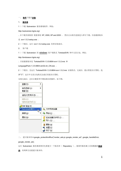
2 )下载后,先运行TortoiseSVN-1.3.5.6804-svn-1.3.2.msi 安装程式,完成后,提示要重启计算机,选择“否”,运行中文语言包程式完成后再重启计算机。
安装完成后,会在右键菜单中增加相应的操作,如下图:二、建立版本库<>google_protectAndRun("render_ads.js::google_render_ad", google_handleError, google_render_ad);运行Subversion 服务器需要首先要建立一个版本库(Repository ),能看作服务器上存放数据的数据库,有两种方法能建立版本库:1、命令行方法:在命令行模式下,运行svnadmin create f:\repository ,即可在F 盘下创建一个版本库repository 。
2、界面操作方法:在F:\repository 目录下,右键,选择TortoiseSVN 下的“在此创建文件库”,文件库类型选择默认的“本地文件系统(FSFS) ”,这样就会在该目录下创建一个版本库。
三、设置用户和权限1、在F:\repository\conf\svnserve.conf 文件中去掉# password-db = passwd 项前面的# 号和空格(空格一定要去掉,否则会报错)。

无刷微型真空泵V30系列产品说明书(Ver.2022.12.23)1产品版本及外观1.1V30(基础型)1.2V30(旋钮调速型)1.3V30(频率调速型)1.4V30(ding配型)2技术参数2.1关键参数注:1、该系列微型泵均使用直流电源,输入电压要求:DC24V±10%(24V型号泵)、DC12V±10%(12V型号泵);所需直流稳压电源为选配件,客户需自配,或也可从我司购买定做好的电源。
2、如无特别说明,技术参数均是在25℃、标准大气压101kPa的条件下的测定值;3、表中参数是在电机MAX转速时测得。
当转速变化时,压力/真空度基本不变;4、表中参数均在标配接口下测得,若选配其他类型接口,参数可能会发生小幅改变;5、表中峰值流量是指用玻璃转子流量计(去掉了针型阀)测得的流量值,平均流量是用皂膜流量计测得的流量值;不建议使用质量流量计进行测量,因原理等原因会导致较大误差(这不是微型泵的问题)。
6、该系列微型泵根据:(1)流量不同可分为:大流量-L,中流量-M,小流量-S;(2)性能、寿命、生产工艺、调试等不同,可分为简化版(简称J,下同)、标准版(B)、品质版(P);(3)功能不同,可细分为基础型(J)、旋钮调速型(X)、频率调速型(H)、ding配型(D);结合版本组合为:简化版-基础型(JJ)、标准版-旋钮调速型(BX)、标准版-频率调速型(BH)、品质版-旋钮调速型(PX)、品质版频率调速型(PH)、品质版-ding配型(PD)。
(4)是否可定做不同材质:①型号中带有后缀“B”的,可定做耐腐蚀材质(隔膜/单向阀材质:FKM(氟橡胶));②无后缀的,默认为:隔膜/单向阀材质:EPDM。
(4)【实例】(订购时,请一定注明流量、版本后缀!):①V30M-JJ-24V,意为V30微型真空泵中,中流量、简化版-基础型,DC24V供电;②V30S-PD-24V,意为V30微型真空泵中,小流量、品质版-ding配型,DC24V供电,品质MAX高,功能MAX齐全产品。
WVC-300(Life)智能微型并网逆变器使用手册微型逆变器的连接器和电缆芯线说明系统组成无线路由器阿里云服务器云智能APPWi-Fi手机控制数据互传双向电表电网开关G光伏阵列3-N-零线1-L-火线2-G-地线-黄&绿-地线(0.75mm )线端接头注、您可以额外选购专业定制的带有T 型连接器的交流总线,用此交流总线作为每条支路的交流总线,手拉手连接后构成模块化的微逆变支干线布线系统。
微型逆变器的LED 指示功能1.红灯长亮-------------微逆变器上电开机,红灯长亮,设备预备工作状态;2.红灯闪烁-------------微逆变器己全面准备好,进入延时开机状态;3.蓝灯快闪-------------MPPT 最大功率点搜索状态;4.蓝灯长亮-------------MPPT 最大功率点锁定状态;5.蓝灯变为红灯长亮----a.孤岛保护; b.频率保护;c.AC电压过欠压保护; d.DC电压过欠压保护;e.故障; f.软件关机;正常工作指示灯闪烁过程:逆变器连接上AC、DC端33灯快闪(MPPT 搜索)微,然后通电红灯长亮秒红灯闪烁0秒蓝最大功率点→→→灯亮,(MPPT锁定)。
→蓝长包装清单配件固定螺丝Micro InverterAC端连接线通讯天线说明书逆变器(0.75mm )(0.75mm )物联网智能微型逆变器使用手册(Life)物联网智能微型逆变器使用手册(Life)物联网智能微型逆变器使用手册(Life)云智能-物联网监控平台智能物联网监控系统(内置WiFi 数据终端)模组式功能可嵌入智能家居系统独立的一机一密使系统更安全智能移动设备多平台适应(Android /IOS )使用2.4G 穿透模式与路由器无缝连接每日发电量统计(千瓦时)节能减排环境分析统计实时交流输出电压、电流、功率显示实时直流输入电压、电流、功率显示历史功率曲线查询(日、周、月)逆变器工作环境温度显示实时功率输出调整限制功能远程逆变器启停功能控制性能稳定品质卓越智能物联科创未来数据通讯模式LoRa 通讯协议智能云A PP注意事项此二维码用于下载APP手机软件下载以及配网连接使用软件下载请使用二维码扫描下方二维码,安装"云智能"客户端应用程式,智能手机系统运行要求:Android 5.0 、IOS 9 及其以上录入设备启动配网初始化设备设备调节1添加设备长按复位键不放,当LED指示灯重新亮起并变成“蓝色灯”长亮显示状态后松开复位键,逆变器将自动完成复位。
一、安全使用为保证安全使用, 在仪表和说明书内使用下面的符号:警告表示如果不按照以下正确的方法进行操作, 可能产生对人身的危害或对仪表的损伤,以及如何避免的方法。
小心表示如果不按照以下正确的方法进行操作, 可能造成仪表的损伤以及如何避免的方法注意提醒使用者对仪表的操作和特性了解的符号。
为了避免操作者和仪表遭受电击和其它危险请遵守以下规则:警告? 在可燃性、易爆性气体、蒸汽存在的场合不要操作此仪表,在这些环境使用此表是极端危险的。
? 切勿将任何两个端子间和端子与接地间施加 30V 以上的电压。
小心? 除了专业的维修人员外, 其他人不得打开仪表外壳。
? 定期用湿布和清洁剂清理仪表的外壳,切勿使用腐蚀性溶剂。
注意? 为保证使用精度,开机后应预热 5分钟。
? 用户若对本仪表有更高的精度要求时,请与生产厂家或经销商联系。
二、仪表面板组成和功能- 1 -- 2 -LCD 显示区说明a显示此符号, 表示仪表处于输出状态 b显示此符号,表示仪表处于输入状c 显示此符号表示仪表处于校准状态d 0 FS : 仪表在校准状态时显示, 表示当前校准的零点或满点等 e: 显示此符号,表示电池将要用完, 现在需要更换(参看具体章节f▲ : 表示当前将要设定的输出位g Ω、 C 、℉ : 表示当前输出值的单位 h 表示接通输出信号i Pt10、 Pt100、 pt200、 pt500、 Cu50、 Cu10 : 表示热电阻(RTD 的分度号三、仪表维护本节提供一些基本的维护步骤。
说明书内不包含的仪表修理、校准以及维护均应由有经验的人员进行。
有关本说明书未提到的维护步骤, 请与本公司的授权服务中心联系。
(1一般维护● 定期用湿布及温和的清洁剂清理仪表的外壳,不要使用研磨剂及溶剂。
● 如果长时间不用,应取出电池。
● 插孔上的脏物或湿气能影响读数。
请遵循以下步骤清洁接线端口:(1 、关闭仪表电源并拆除所有的测试线。
(2 、清洁接线端口上的脏物。
TLC V03 灯光控制板使用说明
1.设备简介
TLC V03灯光控制板主要作用是采集数字相机的频闪灯和闪光灯信号并转化成可控脉宽的频闪和闪光灯控制信号输出。
并提取市电的过零信号转化成频率可控的脉冲,作为相机的采样同步信号,避免因市电过零时拍照而造成的图像失真问题。
在工程中根据实际情况调整灯光控制板相应的参数可使数字相机达到最佳拍摄效果
本板所有参数控制均由拨码开关设置。
1.1接口说明:
灯光控制板对外接口见表一,灯光板系统连接示意图见图一
图一系统连接示意图
表一灯光控制板接口描述
1.2 技术性能
2.参数设置
拨码开关键位的定义:当拨到ON的位置时代表数0 ,相反代表数字1。
例如上图的二进制数值=0x00
2.1拨码开关定义
拨码开关S1
拨码开关S2
拨码开关S3
2.2跳线选择
通过调整JP3 和JP4上的跳线帽来选择外部输入频闪和抓拍闪光信号类型。
如下图
通过调节JP5选择相机外同步信号源(只针对CY-200NA类相机)
通过调节JP6选择闪光1输出方式
通过调节JP10选择闪光1、补光1 、频闪1-3输出电压值
2.3光控调整方法
插上光敏电阻,先将S2 第8为拨到1的位置,此时灯受光控控制其亮灭。
再把S3的第8位拨到1的位置,此时灯的亮灭由瞬时环境光强决定。
然后在环境光强大约在50~200lux的环境下,反复调整VR1,使灯光的亮和灭处于临界状态,然后把S3的第8位拨到0的位置,完成调整。
3.接线柱说明
P2是一个6联接线柱上面信号说明见下表
P5 接口说明
建议使用缺省设置:具体设置方法如下 拨码开关S1 6
(1)7(0)8(0)
JP5 不接跳线帽,不使用同步信号,由相机自己控制帧率 JP6 接在EF 上,闪光1信号由相机产生 这种接法支持标准的相机及灯光设置
4. 灯光控制板升级说明
灯光控制板升级接线图
1. 按上图接好串口线
2. JP7插上短接子
3. 运行 LPC210x_ISP.exe ,见下图
4. 按复位键
5.点击键,如果失败请重复4~5步骤,直到读取ID成功
6.选择升级文件
7.点击键直到升级成功
8.取掉JP7短接子,复位。
升级控制台见附件。