关于汽车千斤顶冲压过程分析和设计文献翻译
- 格式:docx
- 大小:1.35 MB
- 文档页数:19

冲压工艺与外文翻译文档1. The mold designing and manufacturingThe mold is the manufacturing industry important craft foundation, in our country, the mold manufacture belongs to the special purpose equipment manufacturing industry. China although very already starts to make the mold and the use mold, but long-term has not formed the industry. Straight stabs 0 centuries 80's later periods, the Chinese mold industry only then drives into the development speedway. Recent years, not only the state-owned mold enterprise had the very big development, the three investments enterprise, the villages and towns (individual) the mold enterprise's development also rapid quietly.Although the Chinese mold industrial development rapid, but compares with the demand, obviously falls short of demand, its main gap concentrates precisely to, large-scale, is complex, the long life mold domain. As a result of in aspect and so on mold precision, life, manufacture cycle and productivity, China and the international average horizontal and the developed country still had a bigger disparity, therefore, needed massively to import the mold every year .The Chinese mold industry must continue to sharpen the productivity, from now on will have emphatically to the profession internal structure adjustment and the state-of-art enhancement. The structure adjustment aspect, mainly is the enterprise structure to the specialized adjustment, the product structure to center the upscale mold development, to the import and export structure improvement, center the upscale automobile cover mold forming analysis and the structure improvement, the multi-purpose compound mold and the compound processing and the laser technology in the mold design manufacture application, the high-speed cutting, the super finishing and polished the technology, the information direction develops . The recent years, the mold profession structure adjustment and the organizational reform step enlarges, mainly displayed in, large-scale, precise, was complex, the long life, center the upscale mold and the mold standard letter development speed is higher than the common mold product; The plastic mold and the compression casting mold proportion increases; Specialized mold factory quantity and its productivity increase; “The three investments" and the private enterprise developsrapidly; The joint stock system transformation step speedsup and so on. Distributes from the area looked, take Zhejiang Delta and Yangtze River delta as central southeast coastal area development quickly to mid-west area, south development quickly to north. At present develops quickest, the mold produces the most centralized province is Guangdong and Zhejiang, places such as Jiangsu, Shanghai, Anhui and Shandong also has a bigger development in recent years.2. Mold Present Status of TechnologyTechni cal level of China’s mold industry currently uneven, with wide disparities generally speaking, with the developed industrial countries, Hong Kong and Taiwan advanced level, there is a large gap.The use of CAD / CAM / CAE / CAPP and other technical design and manufacture molds, either wide application, or technical level, there is a big gap between both. In the application of CAD technology design molds, only about 10% of the mold used in the design of CAD, aside from drawing board still has a long way to go; in the application of CAE design and analysis of mold calculation, it was just started, most of the game is still in trial stages and animation; in the application of CAM technology manufacturing molds, first, the lack of advanced manufacturingequipment, and second, the existing process equipment (including the last 10 years the introduction of advanced equipment) or computer standard (IBM PC and compatibles, HP workstations, etc.) different, or because of differences in bytes, processing speed differences, differences in resistance to electromagnetic interference, networking is low, only about 5% of the mold manufacturing equipment of recent work in this task; in the application process planning CAPP technology, basically a blank state, based on the need for a lot of standardization work; in the mold common technology, such as mold rapid prototyping technology, polishing, electroforming technologies, surface treatment technology aspects of CAD / CAM technology in China has just started. Computer-aided technology, software development, is still at low level, the accumulation of knowledge and experience required. Most of our mold factory, mold processing equipment shop old, long in the length of civilian service, accuracy, low efficiency, still use theordinary forging, turning, milling, planning, drilling, grinding and processing equipment, mold, heat treatment is still in use salt bath, box-type furnace, operating with the experience of workers, poorly equipped, high energy consumption. Renewal ofequipment is slow, technological innovation; technological progress is not much intensity. Although in recent years introduced many advanced mold processing equipment, but are too scattered, or not complete, only about 25% utilization, equipment, some of the advanced functions are not given full play.3. Die trend(1) Mold software features integratedDie software features of integrated software modules required relatively complete, while the function module using the same data model, in order to achieve Syndicated news management and sharing of information to support the mold design, manufacture, assembly, inspection, testing and production management of the entire process to achieve optimal benefits. Series such as the UK Delcam's software will include a surface / solid geometric modeling, engineering drawing complex geometry, advanced rendering industrial design, plastic mold design expert system, complex physical CAM, artistic design and sculpture automatic programming system, reverse engineering and complex systems physical line measurement systems. A higher degree of integration of the software includes:Pro / __R, UG and CATIA, etc.. Shanghai Jiao tong University, China with finite element analysis of metal plastic forming systems and Die CAD / CAM systems; Beijing Bei hang Haier Software Ltd. CAXA Series software; Jilin Gold Grid Engineering Research Center of the stamping die mold CAD / CAE / CAM systems.(2) Mold design, analysis and manufacture of three-dimensionalTwo-dimensional mold of traditional structural design can no longer meet modern technical requirements of production and integration. Mold design, analysis, manufacturing three-dimensional technology, paperless software required to mold a new generation of three-dimensional, intuitive sense to design the mold, using three-dimensional digital model can be easily used in the product structure of CAE analysis, tooling manufacturability evaluation and CNC machining, forming processsimulation and information management and sharing. Such as Pro / E, UG and CATIA software such as with parametric, feature-based, all relevant characteristics, so that mold concurrent engineering possible. In addition, Cimarron company Mold expert, Delcam's Ps-mold and Hitachi Shipbuilding ofSpace-E/mold are professional injection mold 3D design software, interactive 3D cavity, core design, mold base design configuration and typical structure . Australian company Mold flow realistic three-dimensional flow simulation software MoldflowAdvisers been widely praised by users and applications. China Huazhong University of Science has developed similar software HSC3D4.5F and Zhengzhou University, Z-mold software. For manufacturing, knowledge-based intelligent software function is a measure of die important sign of advanced and practical one. Such as injection molding experts Cimarron’s software can automatically generate parting direction based parting line and parting surface, generate products corresponding to the core and cavity, implementation of all relevant parts mold, and for automatically generated BOM Form NC drilling process, and can intelligently process parameter setting, calibration and other processing results.(3) Mold software applications, networking trendWith the mold in the enterprise competition, cooperation, production and management, globalization, internationalization, and the rapid development of computer hardware and software technology, the Internet has made in the mold industry, virtualdesign, and agile manufacturing technology both necessary and possible.4. Heat Treatment of DieTraditional die and mould design, mainly by experience or semi―experience,is isolated from manufacturing process. Before the design is finalized,the scheme of die and mould is usually modified time and again,thus some disadvantages come into being, such as long development period, high cost and uncertain practical effect. Due to strong desires for precision, service life, development period and cost, modern die and mould should be designed and manufactured perfectly. Therefore more and more advanced technologies and innovations have been applied, for example, concurrentengineering, agile manufacturing virtual manufacturing, collaborative design, etc. Heat treatment of die and mould is as important as design, manufacture and assembly because it has a vital effect on manufacture,assembly and service life.Design and manufacture of die and mould have progressed rapidly,but heat treatment lagged seriously behind them.As die and mould industry develops,heat treatment must ensure die and mould there are good state of manufacture,assembly andwear―resistant properties by request. Impertinent heat treatment can influence die and mould manufacturing such as over―hard and―soft and assembly.Traditionally the heat treatment process was made out according to the methods and properties brought forward by designer.This could make the designers of die and mould and heat treatment diverge from each other,for the designers of die and mould could not fully realize heat treatment process and materials properties,and contrarily the designers rarely understood the service environment and designing thought. These divergences will impact the progress of die and mould to a great extent. Accordingly,if the process design of heat treatment is considered in the early designing stage,the aims of shortening development period,reducing cost and stabilizing quality will be achieved and the sublimation of development pattern from serial to concurrent will be realized.Concurrent engineering takes computer integration system as a carrier, at the very start subsequent each stage and factors have been considered such as manufacturing,heat treating,properties and so forth in order to avoid the error.The concurrent pattern has dismissed the defect of serial pattern, which bringabout a revolution against serial pattern.In the present work.the heat treatment was integrated into the concurrent circumstance of the die and mould development,and the systemic and profound research was performed.5. SummaryThe 21st century, in the new situation of economic globalization, with capital, technology and labor market re-integration of equipment manufacturing in China after joining the WTO will become the world's equipment manufacturing base. In the modern manufacturing industry, no matter which industry, engineering equipment, are increasingly used to provide the products from the mold industry. In order to meet the user's high-precision mold manufacturing, short delivery time, the urgent demand low-cost, mold industry is extensive application of modern advanced manufacturing technology to speed up the mold industry, technological progress, to meet the basic sectors of the mold process equipment urgent needs.。

武汉轻工大学毕业设计(论文)外文参考文献译文本2013届译文出处Modeling of Optimal Screw Jack Design 毕业设计(论文)题目螺旋千斤顶仿真设计院(系)机械工程学院专业名称机械设计制造及其自动化学生姓名学生学号指导教师译文要求:1、译文内容须与课题(或专业)有联系;2、外文翻译不少于4000汉字。
螺旋千斤顶的最优设计建模摘要:本文旨在使用在AutoCAD软件包中的VBA编程功能实现螺旋千斤顶的最优造型设计。
当下市场需求的增长需要良好的设计和优质的产品,同时希望花费尽可能短的时间,以达到更好的产品体验。
数字世界软件的发展在满足大量的要求上起到了重要的作用,因此笔者考虑用CAD软件来开发设计螺旋千斤顶。
该应用程序软件的指令是面向开发者而不是面向用户的。
当用户操作这款软件时,他们需要花相当长的时间来完成复杂的3D建模的设计。
在AutoCAD中,程序语言被嵌入到宏之中来满足我们的设计需求,并以此作为编程语言。
它包括Lisp 编程,自动编程,对话控制语言程序设计,Visual Basic编程。
本文设计的螺旋千斤顶使用Visual Basic辅助编程与AutoCAD的嵌入式编程语言开发。
Visual Basic 语言编程软件具有对于使用者的亲和力,这是一种Windows应用程序。
设计中所使用的对话框和代码的扩充,使之比其他在AutoCAD中的语言更容易调试。
基本上,三维建模设计需要占用一个巨大的空间来保存其操作进程,也不方便从一个系统转移到另一个系统配置。
该编程语言,占用空间小,也容易通过一个小的存储盘转移到其他系统的配置。
建模,2D设计以及其他的参数设计也很容易同时通过本文推荐的这款软件的对话框找到。
当点击对话框中的需要的命令按钮后,这个软件拥有螺旋千斤顶的造型优化设计代码。
这个软件就会一步步的执行语句来处理参数。
如果任何参数不是最优解,将忽略用户自定义的参数要求产生经精确设计的优化参数,并提供良好的设计。

毕业设计中英文翻译资料--冲压成形与板材冲压Stamping and Sheet Metal Forming1.The article overviewStamping is a kind of plastic forming process in which a part is produced by means of the plastic forming the material under the action of a die. Stamping is usually carried out under cold state, so it is also called stamping. Heat stamping is used only when the blank thickness is greater than 8~100mm. The blank material for stamping is usually in the form of sheet or strip, and therefore it is also called sheet metal forming. Some non-metal sheets (such as plywood, mica sheet, asbestos, leather)can also be formed by stamping.Stamping is widely used in various fields of the metalworking industry, and it plays a crucial role in the industries for manufacturing automobiles, instruments, military parts and household electrical appliances, etc.The process, equipment and die are the three foundational problems that needed to be studied in stamping.The characteristics of the sheet metal forming are as follows:(1)High material utilization(2)Capacity to produce thin-walled parts of complex shape.(3)Good interchangeability between stamping parts due to precision in shape anddimension.(4)Parts with lightweight, high-strength and fine rigidity can be obtained.(5)High productivity, easy to operate and to realize mechanization andautomatization.The manufacture of the stamping die is costly, and therefore it only fits to mass production. For the manufacture of products in small batch and rich variety, the simple stamping die and the new equipment such as a stamping machining center, are usually adopted to meet the market demands.The materials for sheet metal stamping include mild steel, copper, aluminum, magnesium alloy and high-plasticity alloy-steel, etc.Stamping equipment includes plate shear punching press. The former shears plate into strips with a definite width, which would be pressed later. The later can be used both in shearing and forming.2.Characteristics of stamping formingThere are various processes of stamping forming with different working patterns and names. But these processes are similar to each other in plastic deformation. There are following conspicuous characteristics in stamping:(1).The force per unit area perpendicular to the blank surface is not large but is enough to cause the material plastic deformation. It is much less than the inner stresses on the plate plane directions. In most cases stamping forming can be treated approximately as that of the plane stress state to simplify vastly the theoretical analysis and the calculation of the process parameters.(2).Due to the small relative thickness, the anti-instability capability of the blank is weak under compressive stress. As a result, the stamping process is difficult to proceed successfully without using the anti-instability device (such as blank holder). Therefore the varieties of the stamping processes dominated by tensile stress are more than dominated by compressive stress.(3).During stamping forming, the inner stress of the blank is equal to or sometimes less than the yield stress of the material. In this point, the stamping is different from the bulk forming. During stamping forming, the influence of the hydrostatic pressure of the stress state in the deformation zone to the forming limit and the deformation resistance is not so important as to the bulk forming. In some circumstances, such influence may be neglected. Even in the case when this influence should be considered, the treating method is also different from that of bulk forming.(4).In stamping forming, the restrain action of the die to the blank is not severs as in the case of the bulk forming (such as die forging). In bulk forming, the constraint forming is proceeded by the die with exactly the same shape of the part. Whereas in stamping, inmost cases, the blank has a certain degree of freedom, only one surface of the blank contacts with the die. In some extra cases, such as the forming of the blank on the deforming zone contact with the die. The deformation in these regions are caused and controlled by the die applying an external force to its adjacent area.Due to the characteristics of stamping deformation and mechanics mentioned above, the stamping technique is different form the bulk metal forming:(1).The importance or the strength and rigidity of the die in stamping forming is less than that in bulk forming because the blank can be formed without applying large pressure per unit area on its surface. Instead, the techniques of the simple die and the pneumatic and hydraulic forming are developed.(2).Due to the plane stress or simple strain state in comparison with bulk forming, more research on deformation or force and power parameters has been done. Stamping forming can be performed by more reasonable scientific methods. Based on the real time measurement and analysis on the sheet metal properties and stamping parameters, by means of computer and some modern testing apparatus, research on the intellectualized control of stamping process is also in proceeding.(3).It is shown that there is a close relationship between stamping forming and raw material. The research on the properties of the stamping forming, that is, forming ability and shape stability, has become a key point in stamping technology development, but also enhances the manufacturing technique of iron and steel industry, and provides a reliable foundation for increasing sheet metal quality.3.Categories of stamping formingMany deformation processes can be done by stamping, the basic processes of the stamping can be divided into two kinds: cutting and forming.Cutting is a shearing process that one part of the blank is cut from the other. It mainly includes blanking, punching, trimming, parting and shaving, where punching and blanking are the most widely used. Forming is a process that one part of the blank has some displacement from the other. It mainly includes deep drawing, bending, local forming,bulging, flanging, necking, sizing and spinning.In substance, stamping forming is such that the plastic deformation occurs in the deformation zone of the stamping blank caused by the external force. The stress state and deformation characteristic of the deformation zone are the basic factors to decide the properties of the stamping forming. Based on the stress state and deformation characteristics of the deformation zone, the forming methods can be divided into several categories with the same forming properties and be studied systematically.The deformation zone in almost all types of stamping forming is in the plane stress state. Usually there is no force or only small force applied on the blank surface. When is assumed that the stress perpendicular to the blank surface equals to zero, two principal stresses perpendicular to each other and act on the blank surface produce the plastic deformation of the material. Due to the small thickness of the blank, it is assumed approximately the two principal stresses distribute uniformly along the thickness direction. Based on this analysis, the stress state and the deformation characteristics of the deformation zone in all kinds of stamping forming can be denoted by the points in the coordinates of the plane principal stresses and the coordinates of the corresponding plane principal strains.4.Raw materials for stamping formingThere are a lot of raw materials used in stamping forming, and the properties of these materials may have large difference. The stamping forming can be succeeded only by determining the stamping method, the forming parameters and the die structures according to the properties and characteristics of the raw materials. The deformation of the blank during stamping forming has been investigated quite thoroughly. The relationships between the material properties decided by the chemistry component and structure of the material and the stamping forming has been established clearly. Not only the proper material can be selected based on the working condition and usage demand, but also the new material can be developed according to the demands of the blank properties during processing the stamping part. This is an important domain in stamping formingresearch. The research on the material properties for stamping forming is as follows: (1).Definition of the stamping property of the material.(2).Method to judge the stamping property of the material, find parameters to express the definitely material property of the stamping forming, establish the relationship between the property parameters and the practical stamping forming, and investigate the testing methods of the property parameters.(3).Establish the relationship among the chemical component, structure, manufacturing process and stamping property.The raw materials for stamping forming mainly include various metals and nonmetal plate. Sheet metal includes both ferrous and nonferrous metals. Although a lot of sheet metals are used in stamping forming, the most widely used materials are steel, stainless steel, aluminum alloy and various composite metal plates.5.Stamping forming property of sheet metal and its assessing methodThe stamping forming property of the sheet metal is the adaptation capability of the sheet metal to stamping forming. It has crucial meaning to the investigation of the stamping forming property of the sheet metal. In order to produce stamping forming parts with most scientific, economic and rational stamping forming process and forming parameters, it is necessary to understand clearly the properties of the sheet metal, so as to utilize the potential of the sheet metal fully in the production. On the other hand, to select plate material accurately and rationally in accordance with the characteristics of the shape and dimension of the stamping forming part and its forming technique is also necessary so that a scientific understanding and accurate judgment to the stamping forming properties of the sheet metal may be achieved.There are direct and indirect testing methods to assess the stamping property of the sheet metal.Practicality stamping test is the most direct method to assess stamping forming property of the sheet metal. This test is done exactly in the same condition as actual production by using the practical equipment and dies. Surely, this test result is mostreliable. But this kind of assessing method is not comprehensively applicable, and cannot be shared as a commonly used standard between factories.The simulation test is a kind of assessing method that after simplifying and summing up actual stamping forming methods, as well as eliminating many trivial factors, the stamping properties of the sheet metal are assessed, based on simplified axial-symmetric forming method under the same deformation and stress states between the testing plate and the actual forming states. In order to guarantee the reliability and generality of simulation results, a lot of factors are regulated in detail, such as the shape and dimension of tools for test, blank dimension and testing conditions(stamping velocity, lubrication method and blank holding force, etc).Indirect testing method is also called basic testing method its characteristic is to connect analysis and research on fundamental property and principle of the sheet metal during plastic deformation, and with the plastic deformation parameters of the sheet metal in actual stamping forming, and then to establish the relationship between the indirect testing results(indirect testing value) and the actual stamping forming property (forming parameters). Because the shape and dimension of the specimen and the loading pattern of the indirect testing are different from the actual stamping forming, the deformation characteristics and stress states of the indirect test are different from those of the actual one. So, the results obtained form the indirect test are not the stamping forming parameters, but are the fundamental parameters that can be used to represent the stamping forming property of the sheet metal.冲压成形与板材冲压1.概述通过模具使板材产生塑性变形而获得成品零件的一次成形工艺方法叫做冲压。
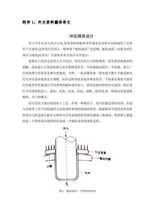
附件1:外文资料翻译译文冲压模具设计对于汽车行业与电子行业,各种各样的板料零件都是有各种不同的成型工艺所生产出来的,这些均可以列入一般种类“板料成形”的范畴。
板料成形(也称为冲压或压力成形)经常在厂区面积非常大的公司中进行。
如果自己没有去这些大公司访问,没有站在巨大的机器旁,没有感受到地面的震颤,没有看巨大型的机器人的手臂吧零件从一个机器移动到另一个机器,那么厂区的范围与价值真是难以想象的。
当然,一盘录像带或一部电视专题片不能反映出汽车冲压流水线的宏大规模。
站在这样的流水线旁观看的另一个因素是观看大量的汽车板类零件被进行不同类型的板料成形加工。
落料是简单的剪切完成的,然后进行不同类型的加工,诸如:弯曲、拉深、拉延、切断、剪切等,每一种情况均要求特殊的、专门的模具。
而且还有大量后续的加工工艺,在每一种情况下,均可以通过诸如拉深、拉延与弯曲等工艺不同的成形方法得到所希望的得到的形状。
根据板料平面的各种各样的受应力状态的小板单元体所可以考虑到的变形情形描述三种成形,原理图1描述的是一个简单的从圆坯料拉深成一个圆柱水杯的成形过程。
图1 板料成形一个简单的水杯拉深是从凸缘型坯料考虑的,即通过模具上冲头的向下作用使材料被水平拉深。
一个凸缘板料上的单元体在半径方向上被限定,而板厚保持几乎不变。
板料成形的原理如图2所示。
拉延通常是用来描述在板料平面上的两个互相垂直的方向被拉长的板料的单元体的变形原理的术语。
拉延的一种特殊形式,可以在大多数成形加工中遇到,即平面张力拉延。
在这种情况下,一个板料的单元体仅在一个方向上进行拉延,在拉长的方向上宽度没有发生变化,但是在厚度上有明确的变化,即变薄。
图2 板料成形原理弯曲时当板料经过冲模,即冲头半径加工成形时所观察到的变形原理,因此在定向的方向上受到改变,这种变形式一个平面张力拉长与收缩的典型实例。
在一个压力机冲程中用于在一块板料上冲出一个或多个孔的一个完整的冲压模具可以归类即制造商标准化为一个单工序冲孔模具,如图3所示。

Design and Fabrication of Hydraulic Jack (SelfJacking)1Jayapradha P, 2Krishna Kumar, 3Priyadharshini1Assistant Professor, 2Student, 3StudentDepartment of Mechanical Engineering, Karpagam Academy of Higher Education, Coimbatore, India_____________________________________________________________________________________________________ Abstract - This paper is regarding the design of fabrication of self-jacking mechanism in four wheeler cars. Driving a car in quite common now a days, whereas tyre failure during the journey is also quite common and unexpected. In this situation lifting a car from the road surface using a mechanical jack is a Hercules task. This process requires excess manual effort and is a time consuming process also. In this regard this mechanism helps to overcome these disadvantages. The motive of this paper is to develop a automatic jacking mechanism that can be operated by the driver from inside the car. The buttons are provided separately in order to convert the right and left side jacks. By pressing the provided button in the dashboard, the inbuilt self jacking mechanism gets activated. This paper deals with the design of fabrication of this mechanism. The reason for using this technique is because of the less power loss and its simple design. Keywords: Hydraulic Jack_____________________________________________________________________________________________________ I. INTRODUCTIONA jack is a mechanical device used as a lifting device in order to lift heavy loads or to exert great forces. In order to perform maintenance process in automobiles, jacks are commonly used. The most common tyre is car jack, floor jack or gauge jack .Basically it is very difficult to operate a mechanical jack. Only skilled labours are able to operate it. Expecting skilled labour all the time is not possible .The main objective of this project is to minimize the manual effort during the jack operation.A mechanical jack is a mobile device which provides mechanical advantage to allow a human to lift heavy equipment. Hydraulic jack works on the principle of Pascal’s law. Blaise pascal[1]derived the basic law of hydraulics. Pascal’s law also known as principles of transmission of fluid –pressure is the statement that in a fluid at rest in a closed container , a pressure change in one part is transmitted without loss to every portion of the fluid and to the walls of the container.∆P = ρg(∆h)Where,∆P is hydrostatic pressureρ is fluid densityg is acceleration due to gravity∆h is height of fluid above the point of measurement.P.S.Rana et al[2] Concludes that implementing the idea of integrated automated jacks for 4 wheelers in which the system can be operated by the button in the dashboard. Mohammed abuzard et al [3] concludes that an inbuilt hydraulic jack system that an inbuilt hydraulic jack system that is fitted to the automobile front and rear chassis. Parth M Patel et al [4] concludes that the implementation of automatic hydraulic jack mechanism in a four wheeler is powered by the battery. Mayanak Agarwal et al [5] concludes that there an inbuilt hydraulic jack system has many benefits and can be easily operated from inside the car by the driver. Aditya Masiwal et al [6] concludes that using the inbuilt hydraulic jack system will be very useful for ladies and old people. P.S Borkar , S.V Sontakke , R.R Dorwe, A.B Ganorkar and S.P Lokhande et al [7] deals with the study and application of pressurical air to produce motion mechanically.1.1 PROBLEM STATEMENTNow a day’s one of the most common and easy thing is driving a car especially among young peoples, ladies to old peoples. But the problem is in the maintenance and the replacement of the car. Although technology has grown to a greater extend, still people face problem in replacing the tyre when it gets punctured at an unexpected place and at an unexpected time. In this regard the one and only situation is to get out of the car, search for the equipment and does the replacement process manually. This process is time taking and a difficult task respectively. Introduction of tubeless tyre have overcome this problem to a particular extend but not completely. in case of a puncture , tubeless tyre also need replacement after a few kilometers of journey . but this project helps to replace the tyre easily and time consumption is also less . this system requires initial implementation cost but provides various benefits during the time of puncture.2. SPECIFICATIONS OF HYDRAULIC JACKThe following specifications were used in fabrication of hydraulic jack.Sl.No. Description Specifications1 Working Load Limit 2000Kg2 Closed Height 180mm3 Lift 115mm4 Extension screw Height 50mm5 Maximum Height 345mm6 Base Area 142mmx92mm7 Weight 2.4KgTable 1. Specification of hydraulic jackFig 1.1 Schematic representation of Self-Jacking mechanism in four wheelers.3. FABRICATION:Two hydraulic jacks were mounted on the top of the frame in accordance with the time of center of gravity. Two motors are used to control the jacks separately. The motors are connected with the crank shaft which is connected to the hydraulic jacks .And also suspension spring is attached at both the sides and the red is attached with the floor bed respectively. The batteries of 12V on each side are soldered and the separate buttons are provided in order to control both side separately. These buttons will be placed on the dashboard when fitted in the vehicle. Four buttons are provided left up, left down, right up and right down respectively. When the left down button is pressed, the left jack is operated making the left floor bed touch the ground resulting in the lifting of left side of the vehicle. This same process is done at the right side by pressing the right down button. Both the buttons can also be pressed simultaneously in order to lift the whole vehicle.Fig 1.2 Image of two hydraulic jacks fitted on the frame.Fig 1.3 Image of arrangement of components on the chassis frame.Fig 1.4 Image of the chassis frame fitted with hydraulic jacks.Fig 1.5 Image of the fabricated self-jacking mechanism prototype model.4. CONCLUSIONThis self jacking mechanism system can be easily installed to the automobile chassis and frames .This systems’s arrangement has many advantages such as maintenance and servicing of the vehicle. At times of puncture this system will be very helpful in saving time as well as reduces manual effort. With the help of this system driving of vehicles will be easy especially for old persons and ladies. People can go on for a long drive without any hesitations. This system eliminates the need to carry a mechanical jack during the time of travel. This system will be easy to use and transmission loss during the operation of this mechanism is also very less. This mechanism performs very well and capable of lifting 125 kgs.•At first trial the prototype was loaded with 65 kgs and the lifting was successful.• At second trial the prototype was loaded with 75 kgs and the lifting was successful.•At third trial the prototype was loaded with 100 kgs and the lifting was successful.•At fourth trial the prototype was loaded with 120 kgs and the lifting was successful.•At fifth trial the prototype was loaded with 125 kgs and the lifting was successful.REFERENCES[1] Jan Schuren, Kay Mohr (2008), Pascal's law and the dynamics of compression therapy: a study on healthy volunteers.[2] P.S. Rana, P.H. Belge, N.A. Nagrare, C.A. Padwad, P.R. Daga, K.B. Deshbhratar, N.K. Mandavgade, (2012), Integrated Automated Jacks for 4-wheelers, European Journal of Applied Engineering and Scientific Research, 2012, 1 (4):167-172 [3] Mohammed Abuzaid, Mohammad Hasnain, Shabaj Alam, Sohail khan, Prof. Surendra Agarwal, (2013), International Journal of Innovations in Engineering and Technology, Vol 2 Issue 2 Pg. 76-84[4] Parth M. Patel, Parth S. Patel, Vaibhav H. Shah, Suril R. Shah, (2016), International Journal Of Scientific & Technology Research Volume 5, Issue 08, August 2016, Pg 156-158[5] Mayank Agrawal, Minti Gehlot Thakur, Deepanshu Mahajan, Tejveer Singh Chahar, (2018), International Research Journal of Engineering and Technology (IRJET), Volume: 05 Issue: 02 Feb-2018 Pg 1386-1390[6] Aditya Masiwal, Aman Kanunga, Ishan Rawlley,Devendra Jha,Ashutosh singh, Dhurv kumar,Ram Jatan Yadhav (2018),International Research Journal of Engineering and Technology(IRJET), volume:05Issue:04/Pg 2842-2847[7] P. S. Borkar, S. V. Sontakke, R. R. Dorwe, A. B. Ganorkar, and S. P. Lokhande, Issue 03, 2015/ “Design of Pneumatic Operated Jack for Four-Wheelers”; International Journal for Scientific Research & Development. Vol. 3ISSN (online): 2321-0613.。
General all-steel punching die’s punching accuracy Accuracy of panel punching part is display the press accuracy of the die exactly. But the accuracy of any punching parts’ linear dimension and positional accuracy almost depend on the blanking and blanking accuracy,. So that the compound mould of compound punching’s accuracy, is typicalness and representation in the majority. Analyse of the die’s accuracyFor the analyse of pracyicable inaccuracy during production of dies to inactivation, we could get the tendency when it is augmentation in most time. From this we could analyse the elements. When the new punch dies pt into production to the first cutter grinding, the inaccuracy produced called initial error; if the die grinding more than twenty times, until it’s discard, the inaccuracy called conventional error; and before the dies discard, the largest error of the last batch permit, called limiting error. at job site, the evidence to confirm life of sharpening is the higher of the blanking, punched hole or punched parts. Because all finished parts had been blanked ,so it is especially for the compound dies. Therefore, the analyse of burr and measurement is especially important when do them as enterprise standardization or checked with <<the height of punching part>>.The initial error usually is the minimal through the whole life of die. Its magnitude depend on the accuracy of manufacture, quality, measure of the punching part, thickness of panel, magnitude of gap and degree of homogeneity. The accuracy of manufacture depend on the manufacture process. For the 1 mm thicked compound punching part made in medium steel, the experimental result and productive practice all prove that the burr of dies which produced by spark cutting are higher 25%~~30% than produced by grinder ,NC or CNC. The reason is that not only the latter have more exact machining accuracy but also the value of roughness Ra is less one order than the formmer, it can be reached 0.025μm. Therefore, the die’s initial blanked accuracy depends on the accuracy of manufacture, quality and so on.The normal error of the punch die is the practicable error when the fist cutter grinding and the last cutter grinding before the die produce the last qualified product. As the increase of cutter grinding, caused the measure the nature wear of the dies are gradual increasing, the error of punching part increase also, so the parts are blew proof. And the die will be unused. The hole on the part and inner because the measure of wear will be small and small gradually, and its outside form will be lager in the same reason. Therefore, the hole and inner form in the part will be made mould according to one-way positive deviation or nearly equal to the limit max measure. In like manner, the punching part’s appearance will be made mould according to one-way negative deviation or nearly equal to limit mini measure. For this will be broaden the normal error, and the cutter grinding times will be increased, the life will be long.The limit error in punching parts are the max dimension error which practicable allowed in the parts with limit error. This kind of parts usually are the last qualified products before the die discard.For the all classes of dies, if we analyse the fluctuate, tendency of increase and decrease and law which appeared in the die’s whole life, we will find that the masterof the error are changeless; the error that because the abrade of the cutter and impression will be as the cutter grinding times increased at the same time. And that will cause the error oversize gradually; and also have another part error are unconventional , unforeseen. Therefore, every die’ s error are composed of fixed er ror, system error, accident error and so on.1. fixed errorAt the whole process when the New punching die between just input production to discard, the changeless master error that in qualified part are called fixed error. It’s magnitude is the deviation when the die production qualified products before the first cutter grinding. Also is the initial error, but the die have initial punching accuracy at this time. Because of the abrade of parts, the die after grinding will be change the dimension error. And the increment of deviation will oversize as the times of cutter grinding. So the punching accuracy after cutter grinding also called “grinding accuracy” and lower tan initial accuracy. The fixed error depend on the elements factor as followed :(1) the material , sorts, structure, (form) dimension, and thick of panelthe magnitude of punching gap and degree of homogeneity are have a important effect for the dimension accuracy. Different punching process, material, thick of panel, have completely different gap and punching accuracy. A gear H62 which made in yellow brass with the same mode number m=0.34, 2mm thick and had a center hole, when the gap get C=0.5%t (single edge) , and punched with compound punching die, and the dimension accuracy reached IT7, the part have a flat surface ,the verticality of tangent plane reached 89.5°, its roughness Ra magnitude are 12.5μm, height of burr are 0.10mm; and the punching part are punched with progressive die, the gap C=7%t (single edge) , initial accuracy are IT11, and have an more rough surface, even can see the gap with eyes. In the usual situation, flushes a material and its thickness t is theselection punching gap main basis. Once the designation gap haddetermined flushes the plane size the fixed error main body; Flushesthe structure rigidity and the three-dimensional shape affects itsshape position precision.(2) punching craft and molder structure typeUses the different ramming craft, flushes a precision and the fixederror difference is really big. Except that the above piece gearexample showed, the essence flushes the craft and ordinary punching flushes a precision and the fixed error differs outside a magnitude,even if in ordinary punching center, uses the different gap punching, thefixed error difference very is also big. For example material thickt=1.5mm H62 brass punching, selects C <= the 40%t unilateral I kind ofsmall gap punching compared to select C <= 8%t (unilaterally) III kindof big gap punching, will flush a fixed error to enlarge 40% ~ 60%, theprecision at least will fall a level. Side in addition, whether thereis picks builds a row of type side, flushes a error to have far to bebigger than has builds a row of type to flush. Side not builds a rowof type to flush. Side not builds a row of type to flush a precisionto be lower than the IT12 level side, but most has builds a row oftype to flush a precision in IT11 between ~ IT9 level, material thickt > 4mm flushes, the size precision can lower some. Different die’s structure type, because is suitable the rammingmaterial to be thick and themanufacture precision difference, causesto flush a fixed error to have leaves. Compound die center, multi-locations continuous type compound die because flushes continuously toduplicate the localization to add on the pattern making error to bebigger, therefore it flushes a fixed error compound punching die to wantcompared to the single location Big 1 ~ 2 levels(3) the craft of punching die’s manufacturethe main work of punching die namely are raised, the concave moldprocessing procedure, to operates on the specification not to behigh, can time form a more complex cavity. But its processing surfaceapproximately is thick > 0.03 ~ 0.05mm is the high temperatureablation remaining furcated austenite organization, degree ofhardness may reach as high as HRC67 ~ 70, has the micro crack, easilywhen punching appears broke the cutter or flaking. The Italian CorradaCorporation''s related memoir called "the line cut the processing contruction to have the disadvantageous influence to the superficialgold, in fact already changed the gold contruction. We must use theJin''gang stone powder to grind or the numerical control continual pathcoordinates rub truncate (cut to line) to make the precision work ". In recent years country and so on Switzerland and Japan, has conductedthe thorough research to the electrical finishing equipment and abigger improvement, makes function complete high accuracy NC and theCNC line cutter, the processing precision may reach ±0.005 ~ 0.001mm,even is smaller. The processing surface roughness Ra value can achieve0.4 mu m. According to the recent years to the domestic 12 productionlines cutter factory investigation and study, the domesticallyproduced line cutter processing precision different factory differentmodel line cutter might reach ±0.008 ~ ±0.005mm, generally all in±0.01mm or bigger somewhat, was individual also can achieve±0.005mm, the processing surface roughness Ra value was bigger than1.6μm. However, the electrical finishing ablation metal surface thus the change and the damage machined surface mental structure character can not change, only if with rubs truncates or other ways removes this harmful level. Therefore, merely uses electricity machining, including the spark cutting and the electricity perforation, achieves with difficulty punching, especially high accuracy, high life punching die to size precision and work components surface roughness Ra value request.With precisely rubs truncates the law manufacture punching die, specially makes the high accuracy, the high life punching die, such as: Thin material small gap compound punching die, multi- locations continuous type compound die and so on, has the size precision high, the work component smachined surface roughness Ra value is small, the mold life higher characteristic. Its processing craft at present changed the electrical fire by the past ordinary engine bed rough machining spark cutting or the electricity puncher rough machining, finally precisely rubs truncates, also from takes shape rubs, optics curve rubs, the manual grid reference rubs gradually filters the continual path grid reference to rub and NC and the CNC continual path grid reference rubs, Processing coarseness may reach ±0.001 ~ 0.0005mm, the processing surface roughness Ra value may reach 0.1 ~ 0.025 mu m. Therefore, with this craft manufacture the die , regardless of the size precision, the work components surfaceroughness, all can satisfy die, each kind of compound request, the die is especially higher than the electrical finishing craft manufacture scale.(4) gap size and degree of homogeneitythe flange and other sheet forming sgene rally all must first punching (fall material) the plate to launch the semi finished materials, after also has the forming to fall the material, the incision obtains the single end product to flush. Therefore punching the work, including is commonly used punching hole, the margin, cut side and so on, regarding each kind of sheet pressing partall is necessary. Therefore punching the gap to flushes a out form in chprecision to have the decisive influence. punching the gap small and is even, may cause punching the size gain high accuracy. Regarding drawability, is curving and so on mould, the gap greatly will decide increases flushes the oral area size error and the snapping back. The gapnon-uniformity can cause to flush a burr enlarges and incurs cutting edge the non-uniform attrition.(5) ramming equipment elastic deformation In the ramming processAfter the punch press load bearing can have the certain elastic deformation. Although this kind of distortion quantity according to flushes the pressure the size to change also to have the obvious directivity, but on the pressing part, mainly is to has the volume ramming archery target stamping, embosses, the equalization, the pressure is raised, the wave, flushes crowds, the shape, the flange, hits flatly, thinly changes draw ability and so on the craft work punching forming flushes, has the significant influence to its ramming aspect size precision普通全钢冲模的冲压精度分析板料冲压件的精度准确显示出其冲模的冲压精度。
附录1Categories of stamping formingMany deformation processes can be done by stamping, the basic processes of the stamping can be divided into two kinds: cutting and forming.Cutting is a shearing process that one part of the blank is cut form the other .It mainly includes blanking, punching, trimming, parting and shaving, where punching and blanking are the most widely used. Forming is a process that one part of the blank has some displacement form the other. It mainly includes deep drawing, bending, local forming, bulging, flanging, necking, sizing and spinning.In substance, stamping forming is such that the plastic deformation occurs in the deformation zone of the stamping blank caused by the external force. The stress state and deformation characteristic of the deformation zone are the basic factors to decide the properties of the stamping forming. Based on the stress state and deformation characteristics of the deformation zone, the forming methods can be divided into several categories with the same forming properties and to be studied systematically.The deformation zone in almost all types of stamping forming is in the plane stress state. Usually there is no force or only small force applied on the blank surface. When it is assumed that the stress perpendicular to the blank surface equal to zero, two principal stresses perpendicular to each other and act on the blank surface produce the plastic deformation of the material. Due to the small thickness of the blank, it is assumed approximately that the two principal stresses distribute uniformly along the thickness direction. Based on this analysis, the stress state and the deformation characteristics of the deformation zone in all kind of stamping forming can be denoted by the point in the coordinates of the plane principal stress(diagram of the stamping stress) and the coordinates of the corresponding plane principal stains (diagram of the stamping strain). The different points in the figures of the stamping stress and strain possess different stress state and deformation characteristics.When the deformation zone of the stamping blank is subjected toplanetensile stresses, it can be divided into two cases, that is σγ>σθ>0,σt=0andσθ>σγ>0,σt=0.Inboth cases, the stress with the maximum absolute value is always a tensile stress. These two cases are analyzed respectively as follows.2)In the case that σγ>σθ>0andσt=0, according to the integral theory, the relationships between stresses and strains are:εγ/(σγ-σm)=εθ/(σθ-σm)=εt/(σt -σm)=k (1.1)where, εγ,εθ,εt are the principal strains of the radial, tangential and thickness directions of the axial symmetrical stamping forming; σγ,σθand σt are the principal stresses of the radial, tangential and thickness directions of the axial symmetrical stamp ing forming;σm is the average stress,σm=(σγ+σθ+σt)/3; k is a constant.In plane stress state, Equation 1.13εγ/(2σγ-σθ)=3εθ/(2σθ-σt)=3εt/[-(σt+σθ)]=k (1.2)Since σγ>σθ>0,so 2σγ-σθ>0 and εθ>0.It indicates that in plane stress state with two axial tensile stresses, if the tensile stress with the maximum absolute value is σγ, the principal strain in this direction must be positive, that is, the deformation belongs to tensile forming.In addition, because σγ>σθ>0,therefore -(σt+σθ)<0 and εt<0. The strain in the thickness direction of the blankεt is negative, that is, the deformation belongs to compressive forming, and the thickness decreases.The deformation condition in the tangential direction depends on the values ofσγand σθ. When σγ=2σθ,εθ=0;when σγ>2σθ,εθ<0;and when σγ<2σθ,εθ>0.The range of σθis σγ>=σθ>=0 . In the equibiaxial tensile stress state σγ=σθ,according to Equation 1.2,εγ=εθ>0 and εt <0 . In the uniaxial tensile stress stateσθ=0,according to Equation 1.2 εθ=-εγ/2.According to above analysis, it is known that this kind of deformation condition is in the region AON of the diagram of the diagram of the stamping strain (see Fig .1.1), and in the region GOH of the diagram of the stamping stress (see Fig.1.2).2)When σθ>σγ >0 and σt=0, according to Equation 1.2 , 2σθ>σγ>0 and εθ>0,This result shows that for the plane stress state with two tensile stresses, when the absoluste value of σθ is the strain in this direction must be positive, that is, it must be in the state of tensile forming.Also becauseσγ>σθ>0,therefore -(σt+σθ)<0 and εt<0. The strain in the thickness direction of the blankεt is negative, or in the state of compressive forming, and the thickness decreases.The deformation condition in the radial direction depends on t he values ofσγ and σθ. When σθ=2σγ,εγ0;when σθ>σγ,εγ<0;and when σθ<2σγ,εγ>0.The range of σγis σθ>= σγ>=0 .When σγ=σθ,εγ=εθ>0, that is, in equibiaxial tensile stress state, the tensile deformation with the same values occurs in the two tensile stress dire ctions; when σγ=0, εγ=-εθ/2, that is, in uniaxial tensile stress state, the deformation characteristic in this case is the same as that of the ordinary uniaxial tensile.This kind of deformation is in the region AON of the diagram of the stamping strain (see Fig.1.1), and in the region GOH of the diagram of the stamping stress (see Fig.1.2).Between above two cases of stamping deformation, the properties ofσθandσγ, and the deformation caused by them are the same, only the direction of the maximum stress is different. These two deformations are same for isotropic homogeneous material.(1)When the deformation zone of stamping blank is subjected to two compressive stressesσγandσθ(σt=0), it can also be divided into two cases, which are σγ<σθ<0,σt=0 and σθ<σγ<0,σt=0.1)When σγ<σθ<0 and σt=0, according to Equation 1.2, 2σγ-σθ<0与εγ=0.This result shows that in the plane stress state with two compressive stresses, if the stress with the maximum absolute value is σγ<0, the strain in this direction must be negative, that is, in the state of compressive forming.Also because σγ<σθ<0, therefore -(σt+σθ)>0 and εt>0.The strain in the thickness direction of the blankεt is positive, and the thickness increases.The deformation condition in the tangential direction depen ds on the values ofσγand σθ.When σγ=2σθ,εθ=0;when σγ>2σθ,εθ<0;and when σγ<2σθ,εθ>0.The range of σθis σγ<σθ<0.When σγ=σθ,it is in equibiaxial tensile stress state, henceεγ=εθ<0; when σθ=0,it is in uniaxial tensile stress state, hence εθ=-εγ/2.This kindof deformation condition is in the region EOG of the diagram of the stamping strain (see Fig.1.1), and in the region COD of the diagram of the stamping stress (see Fig.1.2).2)When σθ<σγ<0and σt=0, according to Equation 1.2,2σθ-σγ<0 and εθ<0. This result shows that in the plane stress state with two compressive stresses, if the stress with the maximum absolute value is σθ, the strain in this direction must be negative, that is, in the state of compressive forming.Also becauseσθ<σγ<0 , therefore -(σt+σθ)>0 and εt>0.The strain in the thickness direction of the blankεt is positive, and the thickness increases.The deformation condition in the radial direction depends on the values ofσγ and σθ. When σθ=2σγ, εγ=0; when σθ>2σγ,εγ<0; and when σθ<2σγ,εγ>0.The range of σγis σθ<= σγ<=0 . When σγ=σθ , it is in equibiaxial tensile stress state, hence εγ=εθ<0; when σγ=0, it is in uniaxial tensile stress state, hence εγ=-εθ/2>0.This kind of deformation is in the region GOL of the diagram of the stamping strain (see Fig.1.1), and in the region DOE of the diagram of the stamping stress (see Fig.1.2).The deformation zone of the stamping blank is subjected to two stresses with opposite signs, and the absolute value of the tensile stress is larger than that of the compressive stress. There exist two cases to be analyzed as follow:1)When σγ>0, σθ<0 and |σγ|>|σθ|, according to Equation 1.2, 2σγ-σθ>0 and εγ>0.This result shows that in the plane stress state with opposite signs, if the stress with the maximum absolute value is tensile, the strain in the maximum stress direction is positive, that is, in the state of tensile forming.Also because σγ>0, σθ<0 and |σγ|>|σθ|, therefore εθ<0. The strain in the compressive stress direction is negative, that is, in the state of compressive forming.The range of σθis 0>=σθ>=-σγ. When σθ=-σγ, then εγ>0,εθ<0 , and |εγ|=|εθ|;when σθ=0, then εγ>0,εθ<0, and εθ=-εγ/2, it is the uniaxial tensile stress state. This kind of deformation condition is in the region MON of the diagram of the stamping strain (see Fig.1.1), and in the region FOG of the diagram of the stamping stress (see Fig.1.2).2)When σθ>0, σγ<0,σt=0 and |σθ|>|σγ|, according to Equation 1.2, bymeans of the same analysis mentioned above, εθ>0, that is, the deformation zone is in the plane stress state with opposite signs. If the stress with the maximum absolute value is tensile stress σθ, the strain in this direction is positive, that is, in the state of tensile forming. The strain in the radial direction is negative (εγ<=0), that is, in the state of compressive forming.The range of σγis 0>=σγ>=-σθ. When σγ=-σθ, then εθ>0,εγ<0 and |εγ|=|εθ|; when σγ=0, then εθ>0,εγ<0, andεγ=-εθ /2. This kind of deformation condition is in the region COD of the diagram of the stamping strain (see Fig.1.1), and in the region AOB of the diagram of the stamping stress (see Fig.1.2).Although the expressions of these two cases are different, their deformation essences are the same.The deformation zone of the stamping blank is subjected to two stresses with opposite signs, and the absolute value of the compressive stress is larger than that of the tensile stress. There exist two cases to be analyzed as follows:1)When σγ>0,σθ<0 and |σθ|>|σγ|, according to Equation 1.2, 2σθ- σγ<0 and εθ<0.This result shows that in plane stress state with opposite signs, if the stress with the maximum absolute value is compressive stress σθ, the strain in this direction is negative, or in the state of compressive forming.Also because σγ>0 and σθ<0, therefore 2σγ- σθ<0 and εγ>0. The strain in the tensile stress direction is positive, or in the state of tensile forming.The range of σγis 0>=σγ>=-σθ.When σγ=-σθ, then εγ>0,εθ<0, and εγ=-εθ;when σγ=0, then εγ>0,εθ<0, and εγ=-εθ/2. This kind of deformation is in the region LOM of the diagram of the stamping strain (see Fig.1.1), and in the region EOF of the diagram of the stamping stress (see Fig.1.2).2)When σθ>0, σγ<0 and |σγ|>|σθ|, according to Equation 1.2 and by means of the same analysis mentioned above,εγ< 0.This result shows that in plane stress state with opposite signs, if the stress with the maximum absolute value is compressive stress σγ,the strain in this direction is negative, or in the state of compressive forming, The strain in the tensile stress direction is positive, or in the state of tensile forming.The range of σθis 0>=σθ>=-σγ.When σθ=-σγ, then εθ>0,εγ<0, and εθ=-εγ;whenσθ=0, then εθ>0,εγ<0, and εθ=-εγ/2. Such deformation is in the region DOF of the diagram of the stamping strain (see Fig.1.1), and in the region BOC of the diagram of the stamping stress (see Fig.1.2).The four deformation conditions are related to the corresponding stamping forming methods. Their relationships are labeled with letters in Fig.1.1 and Fig.1.2.The four deformation conditions analyzed above are applicable to all kinds of plane stress states, that is, the four deformation conditions can sum up all kinds of stamping forming in to two types, tensile and compressive. When the stress with the maximum absolute value in the deformation zone of the stamping blank is tensile, the deformation along this stress direction must be tensile. Such stamping deformation is called tensile forming. Based on above analysis, the tensile forming occupies five regions MON, AON, AOB, BOC and COD in the diagram of the stamping stain; and four regions FOG, GOH, AOH and AOB in the diagram of the stamping stress.When the stress with the maximum absolute value in the deformation zone of the stamping blank is compressive, the deformation along this stress direction must be compressive. Such stamping deformation is called compressive forming. Based on above analysis, the compressive forming occupies five regions LOM, HOL, GOH, FOG and DOF in the diagram of the stamping strain; and four regions EOF, DOE, COD and BOC in the diagram of the stamping stress.MD and FB are the boundaries of the two types of forming in the diagrams of the stamping strain and stress respectively. The tensile forming is located in the top right of the boundary, and the compressive forming is located in the bottom left of the boundary.analysis mentioned above,εγ< 0.This result shows that in plane stress state with opposite signs, if the stress with the maximum absolute value is compressive stress σγ,the strain in this direction is negative, or in the state of compressive forming, The strain in the tensile stress direction is positive, or in the state of tensile forming.The range of σθis 0>=σθ>=-σγ.When σθ=-σγ, then εθ>0,εγ<0, and εθ=-εγ;when σθ=0, then εθ>0,εγ<0, and εθ=-εγ/2. Such deformation is in the region DOF of the diagram of the stamping strain (see Fig.1.1), and in the region BOC of the diagram ofthe stamping stress (see Fig.1.2).The four deformation conditions are related to the corresponding stamping forming methods. Their relationships are labeled with letters in Fig.1.1 and Fig.1.2.The four deformation conditions analyzed above are applicable to all kinds of plane stress states, that is, the four deformation conditions can sum up all kinds of stamping forming in to two types, tensile and compressive. When the stress with the maximum absolute value in the deformation zone of the stamping blank is tensile, the deformation along this stress direction must be tensile. Such stamping deformation is called tensile forming. Based on above analysis, the tensile forming occupies five regions MON, AON, AOB, BOC and COD in the diagram of the stamping stain; and four regions FOG, GOH, AOH and AOB in the diagram of the stamping stress.When the stress with the maximum absolute value in the deformation zone of the stamping blank is compressive, the deformation along this stress direction must be compressive. Such stamping deformation is called compressive forming. Based on above analysis, the compressive forming occupies five regions LOM, HOL, GOH, FOG and DOF in the diagram of the stamping strain; and four regions EOF, DOE, COD and BOC in the diagram of the stamping stress.MD and FB are the boundaries of the two types of forming in the diagrams of the stamping strain and stress respectively. The tensile forming is located in the top right of the boundary, and the compressive forming is located in the bottom left of the boundary.Because the stress produced by the plastic deformation of the material is related to the strain caused by the stress, there also exist certain relationships between the diagrams of the stamping stress and strain. There are corresponding locations in the diagrams of the stamping stress and strain for every stamping deformation. According to the state of stress or strain in the deformation zone of the forming blank, and using the boundary line in the diagram of the stamping stress MD or the boundary line in the diagram of the stamping strain FB, it is easy to know the properties and characteristics of the stamping forming.The locations in the diagrams of the stamping stress and strain for various stressstates and the corresponding relationships of the two diagrams are listed in Table 1.1.It shows that the geometrical location for every region are different in the diagrams of the stamping stress and strain, but their sequences in the two diagrams are the same. One key point is that the boundary line between the tensile and the compressive forming is an inclined line at 45°to the coordinate axis. The characteristics of the stamping technique for tensile and compressive forming are listed in Table 1.2.Table 1.2 clearly shows that in the deformation zone of the blank, the characteristics of the force and deformation, and the patterns relevant to the deformation for each stamping method are the same. Therefore, in addition to the research on the detail stamping method, it is feasible to study stamping systematically and comprehensively. The characteristic of the systematic research is to study the common principle of all different types of stamping methods. The results of the systematic research are applicable to all stamping methods. The research on the properties and limit of the sheet metal stamping has been carried out in certain extent. The contents of the research on the stamping forming limit by using systematic method are shown in Fig.1.附录2冲压变形冲压变形工艺可完成多种工序,其基本工序可分为分离工序和变形工序两大类。
Automobile manufacture stamping process of new development Automobile manufacture has a 60-70% of metal parts must be approved by the plastic processing forming, stamping process is complete metal plastic forming a kind of important means, it is the most basic, the most traditional, the most important one of metal processing method. Such as vehicle body all kinds of covering parts, car support pieces, structure strengthen pieces, there's plenty of auto parts, such as engine exhaust muffler, hollow tube bending and camshaft, the oil pan, engine stents, frame structure, horizontal longeron etc, it is by stamping technology positively precision, multi-function, high efficiency and energy saving, safe cleaning production direction, stamping workpiece manufacturing technology level and quality, in great degree of automobile manufacturing quality and cost has direct impact.So-called stamping technology refers to the adaptability of the stamping to handicraft, namely the design of stamping in size, size accuracy and benchmarks, structure shape stamping processing of compliance with technological requirements. Automotive stamping parts should be good technological characteristics, and the economy, measure the level of the important symbol has stamping process number, body assemblies block number and size, stamping structure, and other factors. Reduce the number of punching process procedure, that means less stamping tooling quantity, number of packages, save simplified punching process of conveyors, Narrows the operators and stamping area, is to save investment and energy consumption extremely good measures, so stamping manufacturers can put punching process reduce vehicle number design as the important way to manufacture cost, even ?Modern stamping development and research of the major subjects include:(1) module type and control。
汽车制造中冲压工艺发展研讨(中英文翻译)Automobile manufacture stamping process of new development Automobile manufacture has a 60-70% of metal parts must be approved by the plastic processing forming, stamping process is complete metal plastic forming a kind of important means, it is the most basic, the most traditional, the most important one of metal processing method. Such as vehicle body all kinds of covering parts, car support pieces, structure strengthen pieces, there's plenty of auto parts, such as engine exhaust muffler, hollow tube bending and camshaft, the oil pan, engine stents, frame structure, horizontal longeron etc, it is by stamping technology positively precision, multi-function, high efficiency and energy saving, safe cleaning production direction, stamping workpiece manufacturing technology level and quality, in great degree of automobile manufacturing quality and cost has direct impact.So-called stamping technology refers to the adaptability of the stamping to handicraft, namely the design of stamping in size, size accuracy and benchmarks, structure shape stamping processing of compliance with technological requirements. Automotive stamping parts should be good technological characteristics, and the economy, measure the level of the important symbol has stamping process number, body assemblies block number and size, stamping structure, and other factors. Reduce the number of punching process procedure, that means less stamping tooling quantity, number of packages, save simplified punching process of conveyors, Narrows the operators and stamping area, is to save investment and energy consumption extremely good measures, so stamping manufacturers can put punching process reduce vehicle number design as the important way to manufacture cost, even ?Modern stamping development and research of the major subjects include:(1) module type and control; stamping(2) new material and composite stamping processing new craft;(3) special stamping technology;(4) computer simulation stamping mold testing technology; and virtual(5) die & mould manufacturing technology,(6) stamping process of automatic monitoring and instability mechanism analysis and so on .Module type stampingModule type of prominent advantages in stamping the stamping processing system of the flexible and efficient production of organic unifies in together. Flexible meaning a broader, such as stamping the geometry of the various demands, so long as can be obtained through the freedom to programming, which reflects the processing shape of flexible. And as both to be suitable mass single variety stamping production, more for small batch multi-species processing play advantage, and also show flexibility. Oerall, module type stamping water-holding point is:(1) the stamping process can be replaced rapidly combination to improve production efficiency; mould(2) due to its strip for belt and masking belt device, can save another set feeding blanking process,(3) achieved great work pieces the non-stop machining,(4) can both independent and can become series of control combination dies action can continually stamping processing;(5) dies with programmable and the flexible characteristics.A module type stamping processing system by a with control function module type of cold stamping press, coil strip send into outfit porch, strip correction machines and programmable feeding device, etc. The stamping system at run-time can undertake stamping transverse displacement, strip feeding positioning, die repeat operation and automatic adjustment work step punching adjustment etc multiple functions. Because the stamping process programmable stamping, make this kind of module type stamping system can adapt production requirements, flexible in same strip on March different workpiece and batch production, realizing mixed non-stop string &joint processing, also in two sides stamping workpiece machining, which has greatly enhanced the work efficiency, have data show that the module type stamping makes processing cost can fall to 40% - 50%.The current module type stamping device integration is very high, in width is300MM size range can arrange of 35 mold, through the roof top of stamping die for independent type series of control, is formed namely die of integrated control. The whole system programmable in WINDOWS user interface and menu under implementation, programming involves mould along the lateral positioning shaft servo drive positioning, strip inspection correction and longitudinal feeding positioning, stamping quality follow-up inspection, punching machine; the adjustment and Condition monitoring and versatility.When stamping reconfigure or alteration, these changes would be parameters and controlled system to store, next time query and invoke. Declarations Die data include the punch and their combination tags, punch combination in X, Y of die and mould shaft Numbers coordinates and other information. Figure 3 shows programmable punching system, figure in A standard mould transverse axis, can undertake servodynamic to stamping area, B for the supporting shaft with punching die, C, D for spare axis to orange roll type with material are feeding.And submillimeter stamping projectAnd submillimeter stamping "refers to the automotive stamping accuracy control at 0 to 1.0 MM within the scope of the traffic in the past, and manufacturing error of2MM compared, is a very big enhancement. This is an improving punching quality and manufacturing technology as the goal of integrated project. The project with"2MM engineering "are all in the late 1990s America QiCheJie conduct large-scale research project. So-called" the car is 2MM engineering knowledge, body assembly size changes within 2MM quantity control, greatly in strict in the original 8MM error range.Stamping processing forming technology affect auto body manufacturing level is one of the key factors, the American experts worked in a car assembly line to over 50 cases field analysis shows that, cause body size error change many reasons, stamping itself size caused by error accumulation 23 percent, its main reason is that the traditional based on experience and original technology based on low level of mold design and manufacturing.And submillimeter stamping is the center of precision stamping with increasing agility two goals, precision is to make the stamping size accuracy control in 0 mm or and submillimeter level, the key is to control body stents, pillar on the pieces of the feet, and make changes in body covering parts, such as partitioned degrees by whole left-right side plate and the top cover plate, etc. Increasing agility meaning is refers to reduce stamping prajapati was preparation time up to 30%, including tooling design, manufacturing and tooling, sample preparation time, in order to achieve greatly shorten the purpose of the new models manufacturing cycle, this project diet aredie-cutting and assembly integration design, stamping system agile design and manufacturing, stamping process of intelligent detecting and monitoring, whole system integration four subsystems project.Through a study of the program and submillimeter stamping, stamping technology has witnessed progress, including:(1) the stamping process and component assembly process design by based on experience and the traditional craft to science and data process of transformation, (2) stamping design to CAD and simulation test mode transformation, rejected traditional attempt method,(3) to implement the mould design manufacture serial manner by the past to parallel transformation,(4) realized process monitoring and equipment maintenance from passive response to scientific prediction type transformation. "2MM project" and "and submillimeter stamping" two project has successively is complete, and the three major automobile manufacturing company popularization and application, and achieved many beneficial results, stamping cost greatly decreased, obtain the growing economic benefit of social benefit, and gradually applied to other countries.Special stamping technologyModern automotive stamping technology requirements towards structure is complex, block size increases, related edge parts more, carrying capacity is large and internal limit strictly etc direction. This requirement and promote special stamping technology such as hydraulic pressure forming, precision forming, explosive forming and spinning forming, no die forming, laser forming and electromagnetic forming technology development. Limited to this paper length, here basically introduces pressure inside the forming and electromagnetic forming two technologies.Modern automotive stamping technology requirements towards structure is complex, block size increases, related edge parts more, carrying capacity is large and internal limit strictly etc direction. This requirement and promote special stamping technology such as hydraulic pressure forming, precision forming, explosive forming and spinning forming, no die forming, laser forming and electromagnetic forming technology development. Limited to this paper length, here basically introduces pressure inside the forming and electromagnetic forming two technologies.The hydraulic or injection of the forming technology of elastic postures, itshigh-pressure forming process generally includes:(1) effective media such as ice expansion iscm make the internal pressure pressed into the penalty extremely slow growth process,(2) fluid static penalty bone high-pressure forming process,(3) extreme pressure as an explosion dynamic process, etc. Medium can is amorphous solid, liquid, or gas, in the system of medium can be basis must processing shape make arbitrary changes, fulfill the punch function, so medium can be equated to a universal mold. Figure 4 is plank super shobach the example, forming from the graph visible at effective media becomes the punch.The hydraulic internal high-pressure forming technology compared with other stamping technology, there are several obvious advantages:(1) the forming process can one processing out like axle, top cover, doorcase and other large and complex 3d geometric shapes of workpiece,(2) because of liquid in the forming process cooling effect, make the workpiece is a "cold strengthening", won than ordinary stamping workpiece machining higher strength, this makes allowing a thinner plank, to make the work more lightweighting;(3) workpiece surface appearance only with pressure liquid contact, pressure is gentle, parts forming process changes, can obtain the symmetry of uniform pressure distribution, and can winner much better smooth outside surface,(4) in stamping and bloom some hydraulic tool charge can reduce 40%, special reduced convex parts processing of takt time is shorter, about 0.1-0.5 MIN, this in special forming process is shorter, may realize the batch production.Using the electromagnetic force generated electricity coil electromagnetic forming process, is the present quite promising another new processing method. This process from 1960s nuclear fission research achievement, but unfortunately has not been people attention. Electromagnetic forming technology principle diagram, when the coil access to electricity. Few microseconds inside establish electromagnetic field, so the metal workpieces especially conductivity strong copper aluminum texture produce electric current, a current, induced current induced by magnetic force and effect, makethe workpiece create tension and dies.the anastomosis and rapid forming. When the coil in the workpiece in electromagnetic force will make workpiece outside of the current application, zhang forming widespread a kind of technology, When the coil planar parallel to the board piece is placed, electromagnetic force will make workpiece stretch forming.Electromagnetic forming technology is a non-contact forming process, and its outstanding merits are shaping a rapid high efficiency, 2 it is often used in metal or nonmetal connection, can replace adhesive or welding, A third is not consumption lymphocy help materials such as lubricating grease, etc, the advantageous environment protection.Stamping process automatic monitoringModern scramjet another important feature is for punching process automatic monitoring to protect the stamping quality. In the mm stamping project automatic detection and monitoring, its research results will include: 1. The stamping process characteristics of online preach diagnosis and detection system, 2. High speed and non-contact measuring system; the stamping 3. Die maintenance scientific prediction system; 4. Stamping key parameters online adjust and compensation system, etc.Stamping process changes caused by workpiece quality is mainly caused by the wear of convex punching die, crack, dislocation, these small changes can be made of high resolution of a transfer sensor and rushed pressure turn sensor tracking detection. One extremely important displacement measurement is a kind of measure, this device, usually by installed in the mould, the GuanYuan and located below the receiving unit constitution, can monitor deviation, tracking processing process, timely output monitoring information and alarm downtime.An online stamping graphical processing system, is the effective guarantee stamping workpiece quality testing method, it can carry out 2-d geometric figure of standard testing, the project has the length, diameter, parallelism, Angle, pressing plank structure and identification of waste, etc. Graphics processing system is by like meter, optical instrument and lighting equipment etc, the standard of CCD like instrument of bashan 750X580 bar lattice resolution for grid and jokshan horizontal direction for every sheshan lattice 0.026 mm, vertical accuracy of fungi mm/sheshan lattice.Surveillance systems use the displacements and the Angle sensor are optical type and electrical type two kinds, the former has the laser testing technology and die like light sheshan technical support, The latter has a inductance and capacitance streaming media, they test accuracy resolution all may achieve the 1-10um grade level. The most suitable stamping technology transfer sensor installation plan is to put multiple turn sensor installed in a centralized sensor board, then put it precisely fixed in the mold outlet, namely the punch clamping board, using sensor data monitoring stamping process, and through the controller get timely treatment, guarantee the quality of the stamping.汽车制造中冲压工艺的新进展汽车制造中有60%-70%的金属零部件需经塑性加工成形,冲压加工是完成金属塑性成形的一种重要手段,它是最差不多、最传统、最重要的金属加工方法之一。
以较少的生产步骤分析和设计汽车千斤顶的冲压过程关键词:Body jack case 汽车千斤顶 Nonlinear finite element analysis 非线性有限元分析Formability 成形性 Sheet metal stamping钣金冲压文献摘要成形性分析是物理试用前成功设计钣金成形工艺的重要步骤。
本篇文章介绍了在工业实践中的一个新的汽车千斤顶形成过程一个设计方法。
这种设计方法需要符合功能和减少生产步骤,相比以往需要的设计当中。
特别是焊接工序。
这一部分可以通过冲压扁钢生产,而且不再需要重复焊接。
冲压工艺师通过使用非线性有限元法(FEM)一致分析地。
成形性是通过使用一个成形极限图(FLD)为主要关键性能指标(KPI)来验证的。
除了成形性,其他制造业方面(即、修剪线和成本)也要考虑在内。
为了确定最佳的工艺条件下,主要参数(即、第一部分的结构、毛坯结构以及结构材料)进行了探索。
在可接受的冲压件下,根据FLD,从逆分析出毛坯结构的结果。
然而,这需要额外的修整成本并且使得冲压件的周长太靠近修剪线。
一个简单的毛坯结构已经表明在本研究中。
它能够满足设计要求,还可以看出,材料的选择部分成形性起着重要的作用。
在这项研究中,JIS SPCE被选择过,JIS SPCC 和JIS SPCEN由于其加工性和成本的优点也分别被选择。
1.介绍很长一段时间,汽车行业一直是世界经济的主要部门。
2006年在泰国,该部门也被视为国家经济发展计划的五大主要工业部门。
在技术方面,在这个行业中有竞争力的重要手段就是尽量减少复杂的制造工艺,并通过高效和有效的设计成本。
典型的汽车零部件制造业发展的总体目标是生产零件形状的一致性和不开裂或者撕裂或者起皱。
通过物理实验,一个试错方法可以实现搜索最佳工艺。
然而,每个实验的设置在汽车零部件行业中通常是非常昂贵的而且是费时的。
在这个工业应用中和显示其他应用程序中,基于仿真设计已经非常具有吸引力。
在最近一些人宋的作品,2007年进行了汽车零件冲压工艺过程中的基于仿真的设计参数研究。
在基准问题相比于模拟预测和实验结果,金属板材成型模型的有效性模拟已经在许多国际会议(如NUMISHEET2005分析论文中)提出并强调。
本篇文章提出了一种汽车千斤顶的制造设计过程。
汽车千斤顶的一个组成部分如图1所示。
该部分通常由钢板冲压工艺所造,而且其顶壳和底座的焊接情况如图2所示。
本研究的主要设计目标就是有一个新的设计,不再需要通过焊接完成,以减少生产过程中的额外费用。
在新的设计理念中,顶壳和底座被合并在一个又吸引力的形状在而且功能保持不变。
这种制造的尝试一直是许多作品的追求。
例如,Cao等,(2001)制作的带有更少步骤形成一个轴对称拉深部分。
本文首先介绍了一个新的部分结构。
然后,工具和材料在本研究中也进行介绍。
非线性有限元分析(FEA)和成形极限图(FLD)被引入作为主要的分析工具。
该分析结果给出了JIS SPCE材料,以保持本文简洁。
然后,该材料的选择(其中JISSPCC,JIS SPCE和JIS SPCEN)被提供。
最后本文的结论被绘制出。
图1-千斤顶的一个例子图2-汽车千斤顶顶壳基本情况2.新的零件结构测试一个制造设计以较少的制造步骤,设计思想是给定的,如图3所示。
对于这个设计,有需要回答下列重要的问题。
是否可以在没有任何瑕疵下制造的设计在一步冲压中,以至于没有必要进行进一步的焊接工艺?哪种材料(在SPCC、SPCE、和SPCEN中)应该被使用?最初的毛坯结构是什么?为了回答这些设计问题,并且有一个成功的产品,设计人员需要对材料变形行为和制造工艺进行充分的理解。
在当今竞争激烈的市场中,良好的生产不仅意味着一种可生产的设计,也包活最容易进行的操作流程,其中包括最低数量的生产步骤,都在这个案例研究中体现。
在汽车千斤顶这个设计过程中,设计者仅打算具有三个步骤:(1)图面(2)修整(3)钻(孔),从这个可以看出,拉拔处理是需要最仔细的工程设计是最重要的过程。
通常,较少的制造步骤意味着更少的操作成本,而且还意味着在每一部有更复杂的操作,因为这些操作被集成在一起。
因此,必须认真核实的理念来整合操作步骤。
图3-千斤顶的一种新设计3.工具和材料在本研究中使用的模具组已经提出,如图4所示,冲压工艺主要包括一个毛坯,一个冲头,粘合剂和一个模具。
图4设计的模具毛坯材料在本研究中的候选是低碳钢薄钢(SPCC,SPCE,SPCEN)。
最初的毛坯厚度为1.6mm。
坯件的密度为7850kg/m3。
杨氏模量(E)为207 GPA。
泊松比(ʋ)为0.28。
SPCC,SPCE,和SPCEN的初始屈服强度(Y)分别为211,176和156MPa。
其真实应力(α)和材料的真实应变(ε)之间的流动曲线假定为遵循幂律如下:其中,K为强度系数,n为硬化指数。
许多金属板材展面内各向异性行为可以通过塑性应变或R值表示。
在大多数工业做法,从三个主要方向的平均R值通常采用如下:其中R0,R45,和R90是从0◦得到的R值,45◦和90◦,分别相对于板材的轧制方向。
这种近似被称为横向各向异性材料。
屈服面的各向同性硬化也采用。
每一种材料的机械性质总结于表1中。
塑性理论的进一步的背景可能会在希尔咨询(1950)和霍斯福德和卡德尔(1993)。
给定的材料模型(即正态分布,横向各向异性,各向同性硬化)是被广泛接受的金属板材成形的应用(见Buranathiti报告和Cao,2005年a,b)。
此外,大多数材料供应商时下能使用这些机械性能。
4.非线性有限元分析在汽车零件的高效设计中,有必要通过一种有效的数学模型来分析金属板料成形过程的成形性能。
金属板材成形过程包含许多困难的机制。
主要是,塑性变形和接触碰撞过程是通过增量显式非线性有限元程序模拟。
明确的代码通常采用以上的工业钣金应用隐式码,在Buranathiti和Cao看出(2005年,B),因为它们的计算时间线性问题的大小,而不是在隐式编码的二次生长。
本文采用Dynaform软件(ETA,2006)和LS-DYNA(LSTC,2006)来验证每一个设计的可成形性。
在本研究中,坯料被建模为一个变形体,而其他组件/工具被建模为刚性体。
毛坯展面是由平面应力假设和五个积分点沿厚度方向采用3D壳单元。
在这个问题上,撕裂和起皱是主要关注的。
回弹现象是不用考虑的,因为在这个过程中主要是受拉,而不是弯曲。
因此,没有必要对七个或者更多的集成点通过数值敏感性分析在一个U型通道形成的获得,如在Buranathiti和Kositpipat(2006)所示,并且即使51点在瓦格纳和Li(2007)在严格的回弹预测表明。
在这项研究中使用的大多数元件是四边形优于三角形元素的元素。
毛坯的初始数值大约为800。
平均单元尺寸为约5mm×5mm的则为约3mm的凹模圆角半径。
然而,当最大网格自适应设定为三个级别,元件尺寸可以减小到0.625毫米×0.625毫米。
模具被建模为刚性体和模具的速度被设定为约2000毫米/秒,以节省计算时间,因为临界时间步长是由材料性能和最小的单元尺寸约束。
粘结力或压边力设定为12,000 N。
的摩擦系数(α)设定为0.125。
在对于每一个形成分析的每一个分析中,有限元分析可以提供应力信息和应变信息。
然而,只有应力信息和应变信息不足时可以得到一个成形性结论,特别是由于塑料稳定现象在金属板材的成形中撕裂。
对塑料的不稳定性相应的材料模型是需要通过FLD。
FLD一直是在金属板材成形分析的重要工具,Keeler和Backofen(1964)和Marciniak 和Kuczynski(1967年)的作品。
在这项工作中,关键性的主应变的解析模型,即,ε∗ 1 and ε∗ 2,FLD从Semitin和Jonas(1984)第一季度采用如下:在这项研究中,首先使用的初始毛坯结构是从通过MSTEP在Dynaform软件使用逆分析(IA)获得,在本篇文章中被称为“毛坯形状”。
逆分析的详细过程和效益可以看出在最近的一次Buranathiti and Cao (2007)的工作。
总之,该部分的中面被用作输入到执行机构,以获得最佳坯料结构。
从现在开始,只有SPCE钢板将用于提供分析结果,以保持演示文稿简洁,而其他钢将总结毛坯结构后计算。
毛坯形状大概从逆分析的结构图5中所示。
对于本篇文章,它简明地标示为情况A。
图5-毛坯形状结构可以看出,这种结构是有些不规则,并且需要复杂的修剪操作,这对于厂家就是一个额外的成本。
因此,一个简单的毛坯构成,在本篇文章中就是所谓的“毛坯尺寸”,经过测试,标价为情况B。
方案B是通过添加大约5mm到每一侧,以成为一个简单的矩形形状,如图6所示定义为相对于情况A.图6-毛坯尺寸#1配置(方案B)然后,另一个简单的毛坯结构进行测试,并且标记为案例C。
情况C被相对情况B定义。
坯料修整在如图7所示中所有四个角,为提前成功实施Buranathiti和Kositpipat(2007)减少皱纹。
探讨一种汽车燃料箱组件的成形设计的工作和发现,修剪四种情况导致了更好的形成部分。
图7-毛坯尺寸#2配置(方案C)。
5.分析结果和讨论每种情况下的设计必须贯彻采用有限元分析和FLD测试,以验证物理试用品可以进行在成形之前的可行性。
有限元模拟已经在PC工作站采用英特尔2.0GHz的氙气和1GB的RAM已进行。
每个模拟需要大约30分钟的计算时间。
但应注意的是,有限元分析可以很好地提供应力和应变的预测。
然而,在可成形性的问题,不能由应力的绝对值被简单地判断。
尽管它有因线性应变历史,其假设的限制,根据基于应变的FLD破坏准则是更合适的KPI。
设计师们鼓励修改KPI模型时,一个更好的破坏准则是可用的。
5.1 情况A从有限元分析和FLD在情况A中提出的新设计的分析结果,提出了图8.该FLD表明,没有裂缝存在于绘制的部分,因为有一个与元素主要应力是上面的状态没有元素应变为基础的成形极限曲线(FLC)或裂纹线。
换句话说,它是可成形的。
尽管周围的凸缘区域的起皱趋势显示在FLD,它仍然是可以接受的,因为该区域由粘合剂抑制。
应当指出,大多数元素的状态是在FLD第二季。
在一个集成的设计中,成形性是不是一个好的设计的唯一指示。
必须有其他制造业方面也需要被考虑在内。
图8-情况A中基于FLD成形性吸取式是用来观察坯料在各拉伸工序的流向另一个参数。
可以看出在图9,该拉入量是有点不均匀,这是所希望的。
在一般情况下,过度的拉伸中,通常引起的裂纹和皱纹。
图9-情况A中拉深从制造点这个角度关注,拉深部分的周边被认为是相对于如图所示的修剪线,如图10所示。
可以看出,该部分的外周太靠近修剪线。
其结果,最终的产品可能不符合设计规格。