电子膨胀阀驱动驱动器
- 格式:xls
- 大小:89.50 KB
- 文档页数:4
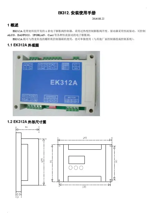
.EK312.安装使用手册-----2016.08.251 概述EK312A是得麦科技开发的1款电子膨胀阀控制器,采用过热度控制膨胀阀开度。
驱动器采用恒流驱动。
可控制ALCO、DANFOSS、SPORLAN、Carel等各种恒流驱动的电子膨胀阀。
EK312A既可与得麦科技的螺杆机控制器联机使用,也可单独使用(与其他厂家控制器组成控制系统)。
1.1 EK312A外观图1.2 EK312A外形尺寸图..1.3 EK312A 电气连接示意图EK312A电气连接示意图B-GA++-G TI DO W3W2W4AI +24G DI Com ComW1MotorB-GND A+ONOFF1234ON OFF1234O NO F FSW2JP2JP1JP3JP4JP5SW1VCCIout SW1地址1234OFF OFF 1ON OFF 2OFF ON 3ON ON4N LAC220VO N O FFSW212345V 10V举例1:12345123412312345612JP2-5设置为4-20mA输入O N O F FSW21234C V 5V 10V 举例2:JP2-5设置为0-10V输入O NO F FSW21234C V 5V 10V电子膨胀阀接线说明:ALCO膨胀阀:W4:白色W3:黑色W2:棕色W1:蓝色Danfoss膨胀阀:W4:黑色W3:白色W2:绿色W1:红色SPORLAN膨胀阀:W4:白色W3:黑色W2:绿色W1:红色Carel膨胀阀:W4:黄色W3:白色W2:棕色W1:绿色地址拔码说明:模拟输入拔码说明:报警输出启停开关电子膨胀阀24V电源输入压力传感器温度传感器通讯线运行故障通讯确认向上向下C V 0|10V0|5V 电压型电流型使用按键显示板备用注1:压力传感器接线:注2:压力传感器接线处,板内供电是24V ,如果传感器不是24V 供电,则要外接电源,之后将电源的负极接到板上的地(JP2-4)即可。

293VALVES - CarelWhy use an Electronic Expansion Valve?Limitations of Mechanical Valves:• Narrow Capacity• Slow movement / reaction • Refrigerant specific • R equires periodical maintenance as the behaviour is unsurveyed.• Requires a solenoid valve on the the liquid line • R equires specific liquid refrigerant temperature / pressure to operateBenefits of an Electronic Expansion Valve:• I ncomparably more precise control, bettersuperheat control = better performance = higher efficiency• Wide capacity range• Quickly adapts to system demand• Non refrigerant specific (Excluding R717)• T he ideal solution when used with variable speed compressors • P ermits floating condensing temperature management • Energy savingWhere is the energy saved?• The energy is primarily saved at the compressor.• H igher efficiency components ensure the system is working at it’s optimal design. This results in longer compressor off periods, or longer periods with the compressor at minimum capacity • E nergy is saved by reducing the operating head pressure, as the high head pressure that would be required for mechanical valves is no longer needed. Operating at Lower head pressures = improved Co-efficient Of Performance of the compressorWhy use a Carel Electronic Expansion Valve?• H igh quality construction = higher efficiency and reliability • T ight shut off guaranteed by unique T eflon seal, seat and blocking spring • Removable stator• Internal gearless, stainless steel mechanism • Bi directional flow capability • E qual percentage flow characteristic ensures accurate control at all valve opening positions294mf .au sales@mf .auCarel - VALVES With capacity ranging from 0.1 kW to2000 kW, there would be a Valve suitable to your application.Valve SizingDue to the vast range of applications and variables to consider when selecting an Expansion valve, it isHIGHL Y suggested the valve is sized correctly by a Refrigeration Engineer.Carel have developed an online sizing tool. It isfreely accessibly but will require a login registration.Go to: /group/exv-sistema/home The virtual sizing console is called ‘Exv Lab’The Application295VALVES- CarelAccessories for EV Series296mf .au sales@mf .auCarel - VALVES EVD Evolution DriversAccessories for EVD DriversEVD Evolution KitsmponentsT o use an electronic valve, the valve will require a valve driver. The Carel range is ever expanding, the primary control to manage an Electronic valve is the EVD Evolution Driver.Other controllers include Ultracella and MPXPRO.Features of the EVD EVO Driver• Superheat management with auxiliary high pressure, low pressure and low superheat protection • Simple start up with just 4 parameters (Refrigerant, application, valve type and sensors)• Ultracap back up integration • Twin version option• Adaptive control algorithms • Digital Scroll suitable• Visual help visible on displayEVD drivers require a pressure transducer and cable, and a strap-on NTC sensorThe kits include a driver, ratiometric pressuretransducer and cable, valve cable and temperature sensor. The display is to be purchased separately.297VALVES - CarelDisplay ModePlease NotePlease read these instructions in conjunction with the parameter list and the installationmanual. It is recommended that the controllers be programmed before connecting or activating the plant to be controlled.An automatic setup procedure appears on the EVD Evo display at startup. The 4 main parameters need to be configured and confirmed to start the driver operation.Installation manual:+0302205EN EVD Evolution+0302206EN EVD Evolution TwinT echnical leaflets:+050004150 EVD Evolution and graphic display +050004155 USB-tLan converter for EVD Evo+050004165 Battery charge and battery for EVD Evo +050004170 EVD Evolution Twin and graphic displayLiterature AvailableMeaning of the LEDsService Parameters (A)Manufacturer Parameters (C)A) PRESS Esc one or more times to switch to the standarvd display PRESS ARROW 'UP' or 'DOWN' to display a graph, the wiring diagram and the main valuesPRESS 'ESC' to exit the display modeA) PRESS Esc one or more times to switch to the standard display B) PRESS 'Prg' to display the password screenC) PRESS 'ENTER' and enter the password '22' then PRESS 'ENTER'D) PRESS ARROW 'UP' or 'DOWN' until reaching the parameter to be modifiedE) PRESS 'ENTER' to access the value. Then PRESS ARROW 'UP' or 'DOWN' to increase or decrease the valueG) PRESS 'ENTER' to save the value Repeat the operations D to G to set other parametersH) PRESS 'Esc' to permanently save the new valuesI) Follow the points A) to C) from the service parameters access with password '66' then PRESS 'ENTER'J) PRESS ARROW 'UP' or 'DOWN' until reaching the category wanted K) PRESS 'ENTER' to access the first parameter in the category. Then PRESS ARROW 'UP' or 'DOWN' until reaching the parameter to be modifiedL) PRESS 'ENTER' to access the value. Then PRESS ARROW 'UP' or 'DOWN' to increase or decrease the valueM) PRESS 'ENTER' to save the value Repeat the operations K to M to set other parametersN) PRESS 'Esc' to permanently savethe new values298mf .au sales@mf .auCarel - VALVESEVD Summary of Operating Parameters299VALVES- CarelKey for Diagram (Electronic Expansion Valves & Drivers)Wiring with Ultracap module EVD0000UC01,3,2,4aa*The transformer size depends on the driver used:For CAREL valves driver use a 20VA transformer.For universal valves driver use a 40VA transformer.Notes on earthingThe shield of the valve cable MUST be earthed.We recommend the use of 1 transformer per driver.Respect the polarity G – G0: If earthing thesecondary of the transformer (24V), only earth G0.Due to the tight shut off of the Carel Electronic Valve, there is no need for a solenoid when an Ultracap power backup module is installed.This device provides enough power to drive the valve shut in the event there is power loss.*The order of the valve connection cable is 1 3 2 4300mf .au sales@mf .auCarel - VALVES。
![mhs_f菜单说明[1]..](https://uimg.taocdn.com/f72849de5acfa1c7ab00cc0d.webp)
MHS_F 控制器菜单说明页脚内容0深圳麦克维尔空调有限公司Shenzhen McQuay Air Conditioning Co.,Ltd.2006-3-5页脚内容1目录目录 (2)1. 主菜单 (4)2. 用户 (4)3. 设置 (8)4. 输入输出 (8)4.1主控制板 (8)4.2扩展板#B (11)4.3扩展板#D (13)5. 故障查询 (14)6. 工厂菜单 (15)7. 服务菜单 (28)8. 时间设置 (37)页脚内容29. 状态查询 (38)10. 版本显示 (40)11. 快捷键 (40)页脚内容3页脚内容4MHS_F 菜单说明1. 主菜单主菜单有三个界面,通过上键和下键可以进行菜单选择,按确定键后进入相应的菜单。
2. 用 户2.1输入用户菜单密码后进入如下的用户菜单,如输入的密码错误,将保持此界面。
密码有4位,按报警键可以让光标向左滚动,按“Prg ”键可以让光标向右滚动。
2.2 系统控制的是出水温度,出水温度的设定点在“设置”菜单里已经设定,在这里还可以对设定值作进一步调整。
该设置有四个选择:“无”、“进水温度”、“4-20mA ”、“OAT ”,默认值为“无”。
“进水温度”指根据进水温度进一步调整出水温度设定点;“4-20mA ”指根据4-20mA 模拟量输入调整出水温度设定点;“OAT ”指根据环境温度调整出水温度设定点。
2.3 “设置菜单”中制冷和制热分别有两个设定值,选择“否”,禁止采用第二个设定值,选择“是”允许采用第二个设定值。
2.4 选择“是”:启用软加载;选择“否”:禁止软加载。
默认为“否”。
2.5 该功能暂不提供,默认“无”。
2.6 压缩机的启动顺序可以选择“自动”和“手动”,选择“自动”,系统会自动根据压缩机的启动次数和运行时间优化压缩机的启动顺序;选择“手动”,进入下一菜单,可以强制设定压缩机的启动顺序。
默认“自动”。
页脚内容5页脚内容62.7 该菜单在压缩机启动顺序选择“手动”时可见。


![mhs_f菜单说明书[1]..](https://uimg.taocdn.com/f102604e844769eae109ed11.webp)
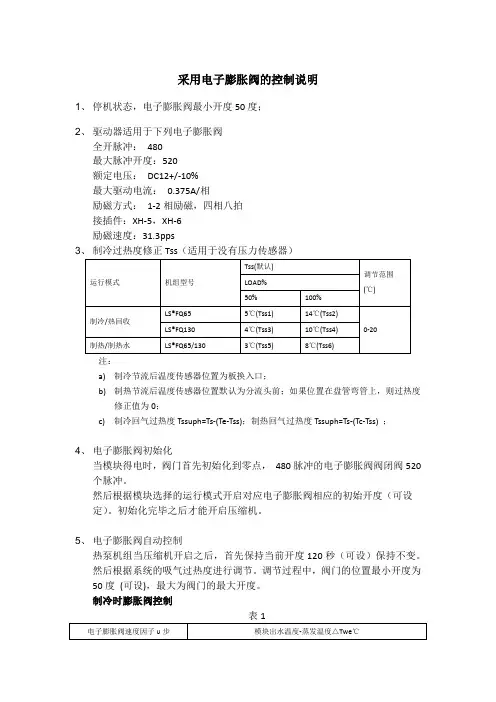
采用电子膨胀阀的控制说明1、停机状态,电子膨胀阀最小开度50度;2、驱动器适用于下列电子膨胀阀全开脉冲:480最大脉冲开度:520额定电压:DC12+/-10%最大驱动电流:0.375A/相励磁方式:1-2相励磁,四相八拍接插件:XH-5,XH-6励磁速度:31.3pps3注:a)制冷节流后温度传感器位置为板换入口;b)制热节流后温度传感器位置默认为分流头前;如果位置在盘管弯管上,则过热度修正值为0;c)制冷回气过热度Tssuph=Ts-(Te-Tss);制热回气过热度Tssuph=Ts-(Tc-Tss) ;4、电子膨胀阀初始化当模块得电时,阀门首先初始化到零点,480脉冲的电子膨胀阀阀闭阀520个脉冲。
然后根据模块选择的运行模式开启对应电子膨胀阀相应的初始开度(可设定)。
初始化完毕之后才能开启压缩机。
5、电子膨胀阀自动控制热泵机组当压缩机开启之后,首先保持当前开度120秒(可设)保持不变。
然后根据系统的吸气过热度进行调节。
调节过程中,阀门的位置最小开度为50度(可设),最大为阀门的最大开度。
制冷时膨胀阀控制表1注:(1)Tss为回气过热度设定值,可调(0-10);(2)Ts为实时计算过热度,计算公式:回气温度-蒸发温度;(3)Te(蒸发温度)=Tee(节流后温度)-Ds,修正值见过热度度修正值;(适用于没有压力传感器机型)(4)脉冲调整1(1-20可调)度/周期(默认90)(10-120s可调),1度为2步;(5)电子膨胀阀调整速度调整因子,见表1;(6)EEV调节间隔时间10-120可调;(7)当Te≥10℃时,EEV不再根据过热度开大;(8)当排气温度≥〖开度只增排气(温度点)〗(默认110,60-120可调), 则膨胀阀不再关小;(9)在正常运行过程中,膨胀阀最小开度不小于50度(并联单压缩机),80度(并联双压缩机或非并联机组);制热膨胀阀控制表2注:1.Ts为回气过热度设定值,可调(0-10);2. Tsup为实时计算过热度,计算公式:回气温度-蒸发温度;3.蒸发温度为板换入口温度修正值,修正值见蒸发温度修正表;(适用于没有压力传感器机型)4.脉冲调整1(1-20可调)度/周期(默认90)(10-120s可调),1度为2步;5.电子膨胀阀调整速度调整因子,见表1;6.EEV调节间隔时间10-120可调;7.当Te≥10℃时,EEV不再根据过热度开大;8.当排气温度≥〖开度只增排气(温度点)〗(默认95,70-120可调), 则膨胀阀不再关小;9.在正常运行过程中,膨胀阀最小开度不小于50度(单压缩机),80度(双压缩机或非并联单压缩机);6、除霜中电子膨胀阀控制当系统进入除霜状态,压缩机关闭后,电子膨胀阀把位置开启到480(可设),除霜过程中保持按自动控制。


电子膨胀阀在制冷系统中如何实现调节和控制电子膨胀阀在空调系统中应用时,能自动调节制冷剂流量,确保空调系统能够始终维持最佳运行工况,可加快制冷速度、精确控制温度,并实现节能。
一、电子膨胀阀在制冷系统中的作用在制冷系统中,电子膨胀阀在控制器内部算法的运用下,结合执行器动作即可实现系统工作参数的采集与控制。
电子膨胀阀负责计算传感器参数,控制则交由控制器负责,因此反应与速度相当显著,仅需几秒就能完成全闭与全开的过程[1]。
采集分为两种:(1)压力型将回气温度与压力作为采集对象,在驱动器内部计算下能将饱和蒸发温度获取,从而完成回气过热度的计算。
(2)温度型主要是对膨胀阀后温度与回气温度采集,从而完成过热度的计算。
驱动器以过热度大小为根据,能对膨胀阀开度实现控制。
二、电子膨胀阀的控制方法1、温度式控制方法系统过热度大致参照两温度的差,同时将其作为电子膨胀阀的控制参数;制冷过热度为ts-te,表示室内蒸发器中央温度对比吸气温度时两者之间相差的数值;制热过热度ts-tc,表示室外冷凝器中央温度对比吸气温度时两者之间相差的数值。
2、压力式控制方法过热度ts-tps中,通过计算获取的数值是控制电子膨胀阀时使用的主要参数,式中的tps代表制冷剂饱和温度,是与吸气压力ps相对应数值,也可以认为过热度是吸入温度与饱和温度之间相差的数值。
3、两种方法对比前一种控制方式安装简便,由于未涉及压力转化到饱和温度的过程,因此能更快的响应。
但是该方法中,过热度与系统实际过热度有一定差异的缘故,难免会有误差存在;后一种控制方式中,计算得到的过热度基本符合实际过热度,然而在回路中有必要进行压力传感器的追加,且程序控制中饱和温度AD转换变的追加也是必不可少的,此时会支出更多成本。
在对两种方法妥当性进行研究时,维持额定制冷条件,记录膨胀阀各个开度时的过热度。
当膨胀阀开度变更,且过热度变化时,两种方法计算获取的过度热之间之间存在大约3 ℃的差值。
EK312.安装使用手册1概述EK312A是得麦科技开发的1款电子膨胀阀控制器,采用过热度控制膨胀阀开度。
驱动器采用恒流驱动。
可控制ALCO、DANFOSS、SPORLAN、Carel等各种恒流驱动的电子膨胀阀。
EK312A既可与得麦科技的螺杆机控制器联机使用,也可单独使用(与其他厂家控制器组成控制系统)。
1.1EK312A外观图1.2EK312A外形尺寸图21.3 EK312A 电气连接示意图EK312A电气连接示意图B-GA++-G TI DO W3W2W4AI +24G DI Com ComW1MotorB-GND A+ONOFF1234ON OFF1234O NO F FSW2JP2JP1JP3JP4JP5SW1VCCIout SW1地址1234OFF OFF 1ON OFF 2OFF ON 3ON ON4N LAC220VO N O F FSW212345V 10V举例1:12345123412312345612JP2-5设置为4-20mA输入O N O F FSW21234C V 5V 10V 举例2:JP2-5设置为0-10V输入O N O F FSW21234C V 5V 10V电子膨胀阀接线说明:ALCO膨胀阀:W4:白色W3:黑色W2:棕色W1:蓝色Danfoss膨胀阀:W4:黑色W3:白色W2:绿色W1:红色SPORLAN膨胀阀:W4:白色W3:黑色W2:绿色W1:红色Carel膨胀阀:W4:黄色W3:白色W2:棕色W1:绿色地址拔码说明:模拟输入拔码说明:报警输出启停开关电子膨胀阀24V电源输入压力传感器温度传感器通讯线运行故障通讯确认向上向下C V 0|10V0|5V 电压型电流型使用按键显示板备用注1:压力传感器接线:注2:压力传感器接线处,板内供电是24V ,如果传感器不是24V 供电,则要外接电源,之后将电源的负极接到板上的地(JP2-4)即可。
2控制逻辑EK312A可选择“吸气过热度”、“手动”、“模拟量控制”3种控制方式(由参数“P33膨胀阀控制方式”设置,默认吸气过热度控制)。