EVD4电子膨胀阀驱动器
- 格式:pdf
- 大小:2.51 MB
- 文档页数:40
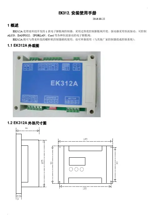
.EK312.安装使用手册-----2016.08.251 概述EK312A是得麦科技开发的1款电子膨胀阀控制器,采用过热度控制膨胀阀开度。
驱动器采用恒流驱动。
可控制ALCO、DANFOSS、SPORLAN、Carel等各种恒流驱动的电子膨胀阀。
EK312A既可与得麦科技的螺杆机控制器联机使用,也可单独使用(与其他厂家控制器组成控制系统)。
1.1 EK312A外观图1.2 EK312A外形尺寸图..1.3 EK312A 电气连接示意图EK312A电气连接示意图B-GA++-G TI DO W3W2W4AI +24G DI Com ComW1MotorB-GND A+ONOFF1234ON OFF1234O NO F FSW2JP2JP1JP3JP4JP5SW1VCCIout SW1地址1234OFF OFF 1ON OFF 2OFF ON 3ON ON4N LAC220VO N O FFSW212345V 10V举例1:12345123412312345612JP2-5设置为4-20mA输入O N O F FSW21234C V 5V 10V 举例2:JP2-5设置为0-10V输入O NO F FSW21234C V 5V 10V电子膨胀阀接线说明:ALCO膨胀阀:W4:白色W3:黑色W2:棕色W1:蓝色Danfoss膨胀阀:W4:黑色W3:白色W2:绿色W1:红色SPORLAN膨胀阀:W4:白色W3:黑色W2:绿色W1:红色Carel膨胀阀:W4:黄色W3:白色W2:棕色W1:绿色地址拔码说明:模拟输入拔码说明:报警输出启停开关电子膨胀阀24V电源输入压力传感器温度传感器通讯线运行故障通讯确认向上向下C V 0|10V0|5V 电压型电流型使用按键显示板备用注1:压力传感器接线:注2:压力传感器接线处,板内供电是24V ,如果传感器不是24V 供电,则要外接电源,之后将电源的负极接到板上的地(JP2-4)即可。


293VALVES - CarelWhy use an Electronic Expansion Valve?Limitations of Mechanical Valves:• Narrow Capacity• Slow movement / reaction • Refrigerant specific • R equires periodical maintenance as the behaviour is unsurveyed.• Requires a solenoid valve on the the liquid line • R equires specific liquid refrigerant temperature / pressure to operateBenefits of an Electronic Expansion Valve:• I ncomparably more precise control, bettersuperheat control = better performance = higher efficiency• Wide capacity range• Quickly adapts to system demand• Non refrigerant specific (Excluding R717)• T he ideal solution when used with variable speed compressors • P ermits floating condensing temperature management • Energy savingWhere is the energy saved?• The energy is primarily saved at the compressor.• H igher efficiency components ensure the system is working at it’s optimal design. This results in longer compressor off periods, or longer periods with the compressor at minimum capacity • E nergy is saved by reducing the operating head pressure, as the high head pressure that would be required for mechanical valves is no longer needed. Operating at Lower head pressures = improved Co-efficient Of Performance of the compressorWhy use a Carel Electronic Expansion Valve?• H igh quality construction = higher efficiency and reliability • T ight shut off guaranteed by unique T eflon seal, seat and blocking spring • Removable stator• Internal gearless, stainless steel mechanism • Bi directional flow capability • E qual percentage flow characteristic ensures accurate control at all valve opening positions294mf .au sales@mf .auCarel - VALVES With capacity ranging from 0.1 kW to2000 kW, there would be a Valve suitable to your application.Valve SizingDue to the vast range of applications and variables to consider when selecting an Expansion valve, it isHIGHL Y suggested the valve is sized correctly by a Refrigeration Engineer.Carel have developed an online sizing tool. It isfreely accessibly but will require a login registration.Go to: /group/exv-sistema/home The virtual sizing console is called ‘Exv Lab’The Application295VALVES- CarelAccessories for EV Series296mf .au sales@mf .auCarel - VALVES EVD Evolution DriversAccessories for EVD DriversEVD Evolution KitsmponentsT o use an electronic valve, the valve will require a valve driver. The Carel range is ever expanding, the primary control to manage an Electronic valve is the EVD Evolution Driver.Other controllers include Ultracella and MPXPRO.Features of the EVD EVO Driver• Superheat management with auxiliary high pressure, low pressure and low superheat protection • Simple start up with just 4 parameters (Refrigerant, application, valve type and sensors)• Ultracap back up integration • Twin version option• Adaptive control algorithms • Digital Scroll suitable• Visual help visible on displayEVD drivers require a pressure transducer and cable, and a strap-on NTC sensorThe kits include a driver, ratiometric pressuretransducer and cable, valve cable and temperature sensor. The display is to be purchased separately.297VALVES - CarelDisplay ModePlease NotePlease read these instructions in conjunction with the parameter list and the installationmanual. It is recommended that the controllers be programmed before connecting or activating the plant to be controlled.An automatic setup procedure appears on the EVD Evo display at startup. The 4 main parameters need to be configured and confirmed to start the driver operation.Installation manual:+0302205EN EVD Evolution+0302206EN EVD Evolution TwinT echnical leaflets:+050004150 EVD Evolution and graphic display +050004155 USB-tLan converter for EVD Evo+050004165 Battery charge and battery for EVD Evo +050004170 EVD Evolution Twin and graphic displayLiterature AvailableMeaning of the LEDsService Parameters (A)Manufacturer Parameters (C)A) PRESS Esc one or more times to switch to the standarvd display PRESS ARROW 'UP' or 'DOWN' to display a graph, the wiring diagram and the main valuesPRESS 'ESC' to exit the display modeA) PRESS Esc one or more times to switch to the standard display B) PRESS 'Prg' to display the password screenC) PRESS 'ENTER' and enter the password '22' then PRESS 'ENTER'D) PRESS ARROW 'UP' or 'DOWN' until reaching the parameter to be modifiedE) PRESS 'ENTER' to access the value. Then PRESS ARROW 'UP' or 'DOWN' to increase or decrease the valueG) PRESS 'ENTER' to save the value Repeat the operations D to G to set other parametersH) PRESS 'Esc' to permanently save the new valuesI) Follow the points A) to C) from the service parameters access with password '66' then PRESS 'ENTER'J) PRESS ARROW 'UP' or 'DOWN' until reaching the category wanted K) PRESS 'ENTER' to access the first parameter in the category. Then PRESS ARROW 'UP' or 'DOWN' until reaching the parameter to be modifiedL) PRESS 'ENTER' to access the value. Then PRESS ARROW 'UP' or 'DOWN' to increase or decrease the valueM) PRESS 'ENTER' to save the value Repeat the operations K to M to set other parametersN) PRESS 'Esc' to permanently savethe new values298mf .au sales@mf .auCarel - VALVESEVD Summary of Operating Parameters299VALVES- CarelKey for Diagram (Electronic Expansion Valves & Drivers)Wiring with Ultracap module EVD0000UC01,3,2,4aa*The transformer size depends on the driver used:For CAREL valves driver use a 20VA transformer.For universal valves driver use a 40VA transformer.Notes on earthingThe shield of the valve cable MUST be earthed.We recommend the use of 1 transformer per driver.Respect the polarity G – G0: If earthing thesecondary of the transformer (24V), only earth G0.Due to the tight shut off of the Carel Electronic Valve, there is no need for a solenoid when an Ultracap power backup module is installed.This device provides enough power to drive the valve shut in the event there is power loss.*The order of the valve connection cable is 1 3 2 4300mf .au sales@mf .auCarel - VALVES。

CVSTDUM0R0+050004150 - rel. 1.7 - 09.01.2013Tabella codici / Table of product codesEVD evolutioncode descriptionEVD0000E00EVD Evolution universal (tLAN)EVD0000E01EVD Evolution universal (tLAN),10 pz* (pcs)EVD0000E10EVD Evolution universal (pLAN)EVD0000E11EVD Evolution universal (pLAN),10 pz* (pcs)EVD0000E20EVD Evolution universal (RS485/Modbus®)EVD0000E21EVD Evolution universal (RS485/Modbus®), 10 pz* (pcs)EVD0000E30EVD Evolution for CAREL valves(tLAN)EVD0000E31EVD Evolution for CAREL valves(tLAN), 10 pz* (pcs)EVD0000E40EVD Evolution for CAREL valves(pLAN)EVD0000E41EVD Evolution for CAREL valves(pLAN), 10 pz* (pcs)EVD0000E50EVD Evolution for CAREL valves(RS485/Modbus®)EVD0000E51EVD Evolution for CAREL valves(RS485/Modbus®), 10 pz* (pcs)EVD0002E10EVD Evolution universaloptoisolated (pLAN)EVD0002E20EVD Evolution universaloptoisolated (RS485/Modbus®)(*) La confezione con imballo multiplo non è fornita di connettori / Th e multiple packages are not supplied with connectorsTabella compatibilità valvole / Table of valve compatibilityModel CAREL E*V****ALCOEX4; EX5; EX6; EX7; EX8 330 Hz (consigliato da CAREL/supported by CAREL ); EX8 500 Hz (da specifi che ALCO/from ALCO specifi cations )SPORLAN SEI 0.5-11; SER 1.5-20; SEI 30; SEI 50; SEH 100; SEH175Danfoss ETS 12.5-25B; ETS 50B; ETS 100B; ETS 250; ETS 400; CCM 10-20-30; CCM 40CAREL Due EXV CAREL collegate insieme / Two CAREL ExV connected together SPORLAN SER(I) G, J, K Montaggio scheda display D isplay board mountingC ompatibilità refrigeranti R efrigerant compatibilityR22; R134a; R404A; R407C; R410A; R507A; R290; R600; R600a; R717; R744; R728; R1270; R417A; R422D; R413A; R422A; R423A; R407A; R427A; R245Fa; R407F; R32; HTR01; HTR02For further information, see the “EEV system guide” (code +030220810) and the user manual (code +0300005EN) available at , under the“Literature” section.to be executed.Modalità di connessioni e alimentazione tL AN , pL AN e RS 485tL AN , pL AN and RS 485 connections and power supplyS chema elettrico per il controllo del surriscaldamento / W iring diagram for superheat controlCaso 1: applicazione di più driver collegati in rete, all’interno dello stesso quadro elettrico, alimentati dallo stesso trasformatore Case 1: a series of drivers is connected in a network, installed in the same electrical panel, powered by the same transformerCaso 2: applicazione di più driver collegati in rete, all’interno di quadri elettrici diversi, alimentati da trasformatori diversi (G0 non connesso a terra).Case 2: a series of drivers is connected in a network, installed in electrical diff erent panels, powered by diff erent transformers (G0 not connected to earth).punto di messa a terra.Case 3: a series of drivers is connected in a network, installed in electrical diff erent panels, powered by diff erent transformers with just one earth point.Per ulteriori informazioni, consultare la “Guida al sistema EEV” (codice +030220810) e il manuale d’uso (codice +03000005IT) disponibili sul sito, alla sezione “Documentazione”.procedura di prima messa in servizio.sovraccarico / Use a class 2 safety transformer, suitably protected against short-circuits and voltage surgesCASO 1/ CASE 1:alimentazione 230 Vac con modulo di emergenza/230 Vac power supply with emergency module CASO 3/ CASE 3:alimentazione 24 Vdc/ 24 Vdc power supplydisplay (accessorio/accessory)codedescriptionEVDIS00CN0Display (Chinese)EVDIS00CZ0Display (Czech)EVDIS00DE0Display (German)EVDIS00EN0Display (English)EVDIS00ES0Display (Spanish)EVDIS00FR0Display (French)EVDIS00IT0Display (Italian)EVDIS00JP0Display (Japanese)EVDIS00PL0Display (Polish)EVDIS00PT0Display (Portuguese)EVDIS00RU0Display (Russian)EVDIS00SE0Display (Swedish)altri accessori/other accessoriesEVDCON0021Kit connettori 10 pz*(connector kit 10 pcs)EVDCNV00E0Convertitore USB/tLAN(USB/tLAN converter)TRADRFE240trasformatore 35VA(35VA transformer)EVD0000UC0Modulo Ultracap(Ultracap module)C AREL INDUSTRIES HQsVia dell’Industria, 11 - 35020 Brugine - Padova (Italy)Tel.(+39)0499716611–Fax(+39)0499716600––e-mail:***************+050004150 - rel. 1.7 - 09.01.2013 CAREL si riserva la possibilità di apportare modifi che o cambiamenti ai propri prodotti senza alcun preavviso. / CAREL reserves the right to modify the features of its products without prior notice.。


电子膨胀阀工作原理及其控制方法探讨【摘要】随着制冷设备的发展,越来越多的高效节能空调产品面世。
而作为制冷系统的四大部件之一,节流装置在制冷系统中起着非常重要的作用,通过选择应用合适的节流机构与制冷系统匹配是整个制冷设备降低能耗的重要一环。
本文将对节流装置其中之一电子膨胀阀的基本结构、工作原理及控制方法进行分析。
【关键词】电子膨胀阀;制冷;节能;节流装置;控制0.引言电子膨胀阀作为一种新型的制冷系统控制部件,突破了传统节流机构的概念,它是制冷系统智能化系统化的重要环节和手段。
空调设备在电子膨胀阀的应用方面,突破了以前在机组设计过程中存在的某种系统屈从热力膨胀阀的观念,进入膨胀阀为系统优化服务的新阶段,其应用使空调设备达到更高的控制精度及工艺要求,对于制冷行业的发展起着重要的作用。
1.传统的节流装置介绍传统的节流装置包括手动节流阀、孔板、热力膨胀阀等。
手动节流阀越来越少见,几乎已经被淘汰。
而孔板只在某一些设备上使用,例如满液式水冷冷水机等。
热力膨胀阀广泛应用于中央空调设备上。
它既可控制蒸发器供液量,又可节流饱和液态制冷剂。
根据热力膨胀阀结构上的不同,分为内平衡式和外平衡式两种。
外平衡式热力膨胀阀在大量使用,其工作原理是建立在感温包内工质压力、蒸发器出口压力及弹簧力平衡的基础上。
但由于热力膨胀阀的感温包具有热容量、传压毛细管的压力传递以及机械动作等系列环节的时间滞后,故,其调节响应速度、精度等远比不上电子膨胀阀。
2.电子膨胀阀介绍2.1结构单从结构上看,电子膨胀阀主要由阀体、阀针、线圈组成。
而从控制实现的角度来看,电子膨胀阀由控制器、执行器和传感器 3 部分构成,通常所说的电子膨胀阀大多仅指执行器,即可控驱动装置和阀体,实际上仅有这一部分是无法完成控制功能的。
电子膨胀阀控制器的核心硬件为单片机,如控制器同时要完成压缩机及风机的变频等控制功能,一般采用多机级连的形式。
电子膨胀阀的传感器通常采用热电偶或热电阻。
XEV22D步进电机型电子膨胀阀驱动器--- 此手册仅适用于软件版本rEL= 0.8的版本 ---1.11.1______________________________________ 1 1.2 _________________________________________________________ 1 2. 概述 _________________________________________________________________________ 1 3. 接线 _________________________________________________________________________ 1 4. 电子膨胀阀的连接与配置 _____________________________________________________ 1 5. 最大功率消耗 ________________________________________________________________ 2 6. 操作面板 _____________________________________________________________________ 2 6.1 XEV22D 的LED 指示灯 __________________________________________________ 2 7. 操作 _________________________________________________________________________ 2 7.1 查看只读参数的值(探头读数、输入输出状态) ________________________ 2 7.2 查看过热度设定点 _____________________________________________________ 2 7.3 修改过热度设定点 _____________________________________________________ 2 7.4 如何进入“Pr1” 层(用户层)参数 _______________________________________ 2 7.5 如何进入“Pr2”层(隐藏层)参数 ________________________________________ 2 7.6 如何修改参数值 _______________________________________________________ 2 8. 参数表 _______________________________________________________________________ 2 9. 数字输入 _____________________________________________________________________ 3 10. 强制开启 _____________________________________________________________________ 4 11. 电气接线 _____________________________________________________________________ 4 11.1 探头的放置 ____________________________________________________________ 4 12. RS485串行通讯 _______________________________________________________________ 4 13. 如何使用热键编程钥匙 _______________________________________________________ 4 13.1 将控制器中数据传输到编程钥匙中(上载) ________________________________ 4 13.2 将编程钥匙中参数下载到控制器 (下载) _________________________________ 4 14. 报警状态信息一览表 __________________________________________________________ 4 14.1 报警复位 ______________________________________________________________ 4 15. 技术数据 _____________________________________________________________________ 4 16. 参数表-出厂默认值 ___________________________________________________________ 41.注意事项 •此控制器不得作以下说明以外的其他用途,不得作安全保护设备使用 • 控制器投入运行前检查应用量程• 不要在水中或潮湿的环境中使用,防止因大气湿度过高引起温度骤变而导致结露。