SNNA电动调节阀说明书
- 格式:pdf
- 大小:642.89 KB
- 文档页数:34

调节阀的操作规程调节阀接受来自中控或现场发出的控制信号,是控制作用的执行者。
调节阀按其能源形式分为气动、液动及电动3大类。
平台上大都采用气动调节阀来控制不同的工艺参数。
这些工艺参数包括压力、温度、液位及流量。
所用的调节阀虽然其尺寸、流量特性及开启方式等有所不同,但多数采用的是FISHER公司生产的不同型号的产品,均为直通单座阀,阀芯顶部导向。
1、工作原理气动调节阀由执行机构及调节阀两部分组成,同时配备一定的辅助装置,如阀门定位器及手轮机构。
气动调节阀工作时,其执行机构接受控制器传送来的控制信号,并根据信号的大小产生相应的推力,推动调节阀动作,从而使被调参数维持在要求的范围内。
(1)、执行机构的工作原理平台所采用的气动调节阀的执行机构大都属于气动薄膜阀式。
当输入信号增加时,其推力使膜片变形,变形的膜片带动推杆移动,当膜片的推力与弹簧的弹离反作用力相等时,推杆停止移动。
此推杆的位移便是执行机构的直线输出,它与输入信号的大小成正比。
(2)、调节阀的工作原理调节阀接受执行机构的推杆输出位移,通过阀杆带动阀芯在阀体内移动,从而改变阀芯与阀座之间的流通面积,达到改变阀对液体的局部阻力,使被调介质的流量相应改变,从而达到调节工艺参数的目的。
(3)、阀门定位器工作原理阀门定位器是启动调节阀的重要附件,用于改善其调节特性。
它具有可调零点、可调量程和进行量程迁移的特性。
阀门定位器安装于控制器与启动调节阀之间,工作时,它接受控制器的控制信号。
经信号转换、比较、放大后,输出与控制信号成比例的确气压信号至气动调节阀的执行机构。
2、检查与维护保养(1)、阀体与执行机构的检查A、检查气源、信号管线、膜片等处有无空气泄漏。
B、检查各密封处有无空气泄漏。
C、检查阀杆及衬套有无裂纹及伤痕。
D、检查阀杆动作是否及时、平稳、有无噪音。
E、检查法兰、垫片的紧固程度,至少每年应对所有法兰和垫片紧固1次。
F、检查润滑情况,必要时加润滑油。
G、检查填料盖的松紧度,不要太紧或太松,标准为以徒手紧固程度稍紧一点为宜。
电动调节阀使用说明格,将面临新的挑战,尤其是在国际矿业巨头继续扩大垄断,谈判双方实力严重失衡的大环境下。
实际上,今年的铁矿石价格谈判时间未到,却早已引起国内外的关注了。
目前,我国铁矿石自给率约为45%至50%,另外一半需要进口,进口分为现货进口和长期协议进口两部分。
作为世界上最大的铁矿石进口国,我国在世界上的地位绝对是举足轻重的。
然而,近几年来,我国钢企参加了几次国际铁矿石价格谈判,但效果都不明显。
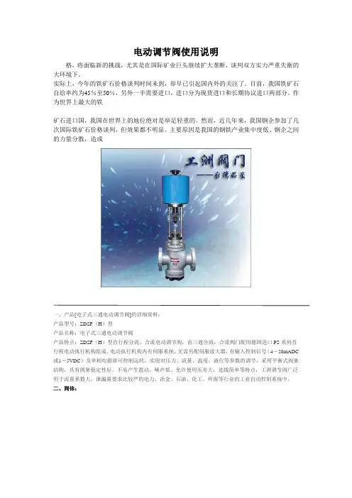
主要原因是我国的钢铁产业集中度低、钢企之间的力量分散,造成一、产品[电子式三通电动调节阀]的详细资料:产品型号:ZDSF(H)型产品名称:电子式三通电动调节阀产品特点:ZDSF(H)型直行程分流、合流电动调节阀,由三通分流,合流阀门配用德国进口PS系列直行程电动执行机构组成。
电动执行机构内有伺服系统,无需另配伺服放大器,有输入控制信号(4-20mADC 或1-5VDC)及单相电源即可控制运转,实现对压力、流量、温度、液位等参数的调节,采用平衡式阀塞结构,具有阀塞稳定性好、不易产生震动、噪声低、允许使用压差大,连线简单等特点,工洲调节阀广泛用于流量系数大,泄漏量要求比较严的电力、冶金、石油、化工、环保等行业的工业自动控制系统中。
二、阀体:形式:三通双座铸造阀公称通径:25-300mm公称压力:PM1.6 4.0 6.4MPa连接形式:法兰式按JB78-59 JB79-59材料:HT200 ZG230—450 ZG1Cr18Ni9TiZG0Cr18Ni12Mo2Ti三、上阀盖:常温型:-20℃-+200℃散热型:-40℃-+450℃压盖形式:螺栓压紧式填料:V型聚四氟乙烯填料、柔性石墨、不锈钢波纹管四、阀内组件:阀芯形式:双导向双座套筒型阀芯流量特性:等百分比特性,线性特性和快开特性材料:1Cr18Ni9Ti 0Cr18Ni12Mo2Ti五、执行机构:类型:可选PS、3810、ZAZ型(DN100以内)、DKZ型(DN100以上)系列电子式直行程执行机构。
西门子电动调节阀安装使用手册济南百通控制设备有限公司我们愿以优质的产品、热情的服务与您携手合作。
为了使我们的产品更好的为您服务,请您详细阅读以下内容。
一、调节阀的工作原理热媒介质流过阀门,经过换热器把被加热介质升温,温度传感器随着被加热介质的温度变化,将信号送至控制器,与设定温度比较运算后将4-20毫安或0-10伏信号送至执行器控制阀门的开度,使热媒介质流量发生变化。
温度的细微变化将使传感器作出响应,改变热媒介质流量,精确控制被加热介质的温度。
二、安装要求安装前请仔细阅读本使用手册,如有疑问请咨询专业技术人员。
不按规程安装操作都可能导致设备损坏或影响使用效果。
1、本产品在出厂前经过严格的检测,尽管如此,在安装前请务必进行检查。
2、请按订货及送货装箱单核实数量及型号。
3、请按上述数量配置进行检验,检查在运输过程中是否有损坏。
三、安装指导图1、安装步聚:(1)阀体应水平安装在一次热媒的入口处,阀杆朝上,确保执行器可垂直于水平面安装。
(2)阀体前应安装过滤器,且直接与阀体对接,选用高目数过滤器。
(3)阀前后安装手动截止阀。
(4)阀侧面应安装旁通,并安装手动截止阀。
(5)若阀前蒸汽压力过高,应安装减压阀,将蒸汽调至设计或最佳工作范围内。
2、安装方式:(正确安装)(错误安装)3、安装要求:(执行器安装):1、将阀杆向上拉起。
2、将执行器安装于阀体上。
3、先用内六方或其它合适的工具预固定执行器底部于阀体连接环槽上。
4、旋转执行器手动旋钮(SQX、SKD系列)或手动摇柄(SKB、SKC系列)将执行器连接凹槽对正(注意:SKB、SKC系列要先将执行器下部连接内螺纹活节拆下,并将连接活节套于阀杆上。
)(传感器安装)(1)在换热器出口处附近开孔,焊丝座。
丝座要求:G1/2``管螺纹,内丝。
(2)丝座建议加工尺寸接管径匹配:(3)将传感器底部螺纹缠绕四氟胶带,沿顺时针方向固定于丝座上。
注意:密封需严密,防止漏水。
(电控箱安装):(1)选择适当地点,一般为便于观察操作的墙面。
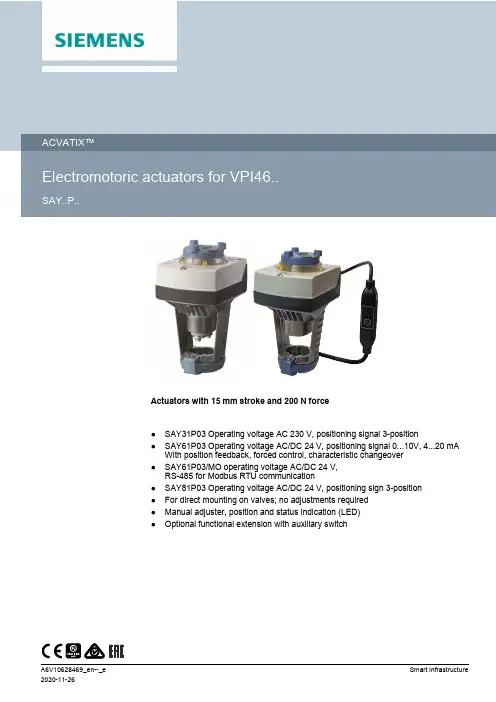
Actuators with 15 mm stroke and 200 N force●SAY31P03 Operating voltage AC 230 V, positioning signal 3-position●SAY61P03 Operating voltage AC/DC 24 V, positioning signal 0...10V, 4...20 mAWith position feedback, forced control, characteristic changeover●SAY61P03/MO operating voltage AC/DC 24 V,RS-485 for Modbus RTU communication●SAY81P03 Operating voltage AC/DC 24 V, positioning sign 3-position●For direct mounting on valves; no adjustments required●Manual adjuster, position and status indication (LED)●Optional functional extension with auxiliary switch2Electromotoric actuators to operate Siemens combi valves for type series VPI46.40F9.5Q and VPI46.50F12Q with 15 mm stroke, as control valves on ventilation, air conditioning,district heating and refrigeration plants.Function DescriptionType 3-position control A 3-position signal controls the actuator via connection terminals Y1 or Y2. The desired position is transmitted to the valve.SAY31P03,SAY81P03Modulating controlThe modulating positioning signal provides stepless motor control.The positioning signal range (DC 0...10 V / DC 4...20 mA / 0...1000Ω) corresponds to the positioning range (closed...open, or 0…100% stroke) in a linear manner.SAY61P03Positioning signal and characteristic changeoverSetting with DIL switch.Factory setting:● Characteristic curve: log = Equal percentage (switch set toOff)●Positioning signal: DC 0...10 V (switch set to Off)Position feedback U Signal returned to acquire the position via input.SAY61 P03,SAY61P03/MO Forced control (Z-mode)Forced control helps override automatic mode and is implemented via higher control.CalibrationCarry out during initial commissioning. The actuator drives to the top or bottom end position; the measured values are saved.Valve seat detectionThe actuators have power-dependent seat detection. After calibration, the exact valve stroke is stored in the actuator's memory.Foreign body detectionAfter clogging is detected, three attempts are made to get past clogging. If unsuccessful, the actuator continues to following the positioning signal only within a limited range, and the LED blinks red.Modbus RTU (RS-485), not galvanically isolated Setpoint 0...100 % valve position Actual value 0...100 % for valve positionOverride control Open / Close / Min / Max / Stop Setpoint monitoring and backup modeSAY61P03/MOType Item No.Stroke Positioning force Operating voltagePositioningsignalSpringreturntimePositioning timeLED ManualadjusterAuxiliaryfunctionsSAY31P031)S55150-A13215 mm200 N AC 230 V3-position-30 s-Push andfix3)SAY61P032)S55150-A133AC 24 VDC 24 VDC ...10 VDC 4...20 mA0...1000 ΩYes4)6)SAY61P03/MO2)S55150-A145Modbus RTU5) SAY81P032)S55150-A1343-position-6)1)Approbation: CE2)Approbation: CE, UL3)Optional accessories: Auxiliary switch4)Position feedback, forced control, characteristic changeover5)Position feedback, forced control6)Optional accessories: Auxiliary switch, sequence control, control action changeoverScope of deliveryActuators, valves and accessories are supplied in individual packs.Accessories/spare partsElectrical accessoriesType Auxiliary switchASC10.51Function moduleAZX61.1Item No.S55845-Z103S55845-Z107SAY31P..Max. 2Max. 1SAY61P..SAY61P../MO-SAY81P..Max. 1Mechanical accessoryType Weather shieldASK39.1Item No.S55845-Z109Ordering (example)Type Stock number Designation Number of piecesSAY81P03S55150-A134Actuator1ASC10.51S55845-Z103Auxiliary switch13Spare partsProduct documentationTitle Contents Document IDActuators SAX.., SAY.., SAV.., SAL.. for valves Basic documentation:Detailed information on stroke actuators includingModbus typesStroke actuators for valves with 15/20/40 mm strokeand rotary actuators for butterfly valvesCE1P4040enElectromotoric actuators for valves SA.., Modbus RTU Data sheet:Modbus communication profilesA6V101037195Mounting instructions G..161../MO and S..6/MO Mounting instructions:Mounting and installation instructions for ModbusactuatorsA5W00027551Valve Actuator DIL Switch Characteristic Overview Commissioning / Configuration:Describes the characteristics of valve and actuatorcombinations, it describes the DIL Switch function.A6V12050595Related documents such as environmental declarations, CE declarations, etc., can bedownloaded at the following Internet address:/bt/download45SafetyCAUTIONNational safety regulationsFailure to comply with national safety regulations may result in personal injury and property damage.● Observe national provisions and comply with the appropriate safety regulations.WARNINGRisk of burns from hot actuator bracketsThe actuator brackets on heating plants can also become hot from the contact with the hot valve during operation. The temperature of the actuator bracket can reach 100 °C.When servicing the actuator:● Switch off both pump and operating voltage.● Close the main shutoff valve in the piping.● Allow the piping to cool off.EngineeringSAY31P03 / SAY81P033-position actuators must be controlled by a controller, see Connection diagrams [➙ 13].SAY61P03Up to 10 actuators can drive in parallel on a controller output with a rating of 1 mA.Modulating actuators have an input impedance of 100 k Ω.SAY61P03/MOThe Modbus converter is designed for analog control at 0...10 V.Keep the analog signal setting on the actuator as is (switch 1 to OFF); adjustment not permitted.MountingMounting positions1)Only together with weather shield ASK39.2. IP54 housing protection remains unchanged.2)SAY61P../MO is not intended for outdoor use.OperationDirection of control actionOn valves where the stem retracts to the close position, "direct acting" means that the valueis fully closed at positioning signal Y = 0 V or Z = 0 Ω (i.e. 100 %).6MaintenanceThe actuators are maintenance-free.DisposalTechnical data on specific applications are valid only together with Siemens products listedunder "Equipment combinations". Siemens rejects any and all warranties in the event thatthird-party products are used.7PowerOperating voltageSAY31P03AC 230 V ±15%SAY61P03..AC 24 V ± 20 % / DC 24 V +20 % / -15 % (SELV /PELV)SAY81P03Frequency45...65 HzExternal supply line fusing (EU)●Non-renewable fuse 6...10 A slow●Circuit break max. 13 A, tripping characteristic B, C,D to EN 60898●Power source with current limitation of max. 10 A Power consumption at 50 HzSAY31P03Stemretracts/extends 6 VA / 3.5 WSAY61P038 VA / 3.75 WSAY61P/MO8.7 VA / 4.25 WSAY81P03 5 VA / 3.75 WTypical inrush current1)(3-position actuators)SAY31P03 2.3 ASAY81P03 4.5 AOperating dataPositioning times (with the specified nominal stroke)The positioning time may vary depending on the type ofvalve(Type summary [➙ 3])SAY31P03, SAY61P03, SAY81P03. 30 sPositioning force200 NNominal stroke15 mmPermissible media temperature (valve fitted) 1...120 °CSignal inputsPositioning signal ”Y”SAY31P03, SAY81P033-positionSAY31P03 Voltage AC 230 V ±15%SAY81P03AC 24 V ± 20% / DC 24 V + 20% / - 15%SAY61P03DC 0...10 V Power consumption≤ 0.1 mA Input impedance ≥100 kΩDC 4...20 mA Power consumption DC 4...20 mA ± 1% Input impedance ≤ 500 kΩ8Communication SAY61P../MOCommunication protocolModbus RTU RS-485, not galvanically isolatedNumber of nodes Max. 32Address range 1...248 / 255Factory setting 255Transmission formats1-8-E-1 / 1-8-O-1 / 1-8-N-1 / 1-8-N-2Factory setting 1-8-E-1Baud rates (kbaud)Auto / 9.6 / 19.2 / 38.4 / 57.6 / 76.8 / 115.2Factory setting AutoBus termination120 Ω electronically switchableFactory setting OffParallel connectionSAY61P03≤ 10 (depending on controller output)Forced controlZ positioning signalSAY61P03R = 0...1000 Ω, G, G0R = 0...1000 ΩStroke proportional to RZ connected to G Max. stroke 100 %2)Z connected to G0Max. stroke 0 %2)Voltage Max. AC 24 V ± 20 % Max. DC 24 V +20% / -15%Power consumption≤ 0.1 mAPosition feedbackPosition feedback USAY61P03DC 0...10 VLoad impedance> 10 kΩ resistiveLoad Max. 1 mAConnection cablesWire cross-sectional areas0.75 mm2, AWG 20...163)Cable entriesSAY..P..● 2 entries∅ 20.5 mm (for M20)● 1 entry∅ 25.5 mm (for M25)SAYP61../MOFixed connection cable 0.9 mNumber of cores 5 x 0.75 mm2Degree of protection and classHousing from vertical to horizontal IP 54 as per EN 605294)Protection class As per EN 60730SAY31P03AC 230 V IISAY61P03AC / DC 24 V IIISAY81P039Environmental conditionsOperation IEC 60721-3-3Climatic conditions Class 3K5Mounting location Indoors (weather-protected)4)Temperature, general-5...55 °CHumidity (non-condensing) 5...95 % r.h.Transportation IEC 60721-3-2Climatic conditions Class 2K3Temperature-25...70 °CHumidity< 95% r.h.Storage IEC 60721-3-1Climatic conditions Class 1K3Temperature-15...55 °CHumidity 5...95 % r.h.Max. media temperature when mounted on valve120 °CDirectives and standardsProduct standard EN 60730-xElectromagnetic compatibility (field of use)For residential, commercial, and industrial environmentsEU conformity (CE)A5W000003335)RCM conformity AC 230 V A5W000003345)EAC compliance Eurasian compliance for all SAY..P..UL, cUL AC 230 V-AC / DC 24 V UL 873 /database; file number E35198Environmental compatibilityProduct environmental declarations 71 7331 05595) und A6V1010832545) include data on environmentallyfriendly product design and testing (RoHS compliance, material composition, packaging, environmental benefits,disposal).DimensionsSee Dimensions [➙ 15]Accessories6)Auxiliary switch ASC10.51Switching capacity AC 24…230 V, 6 (2) A, potential freeExternal fusing of supply line●Non-renewable fuse 6...10 A slow●Circuit break max. 13 A, tripping characteristic B, C,D to EN 60898●Power source with current limitation of max. 10 AUS installation, UL & cUL AC 24 V class 2, 5 A general purpose1)Switching time for RMS value of the sine wave at nominal voltage2)Observe acting direction of DIL switches3)AWG = American wire gauge4)For outdoor operation, always use weather shield ASK39.1, housing protection class IP 54 remains as is.SAY61P../MO is not intended for outdoor use.5)Documents can be downloaded at /bt/download6)UL-approved component10Internal DiagramsSAY31P03SAY61P..Connection terminalsSAY31P03SAY61P03AC / DC 24 V D 0...10 V4...20 mA0 (1000)System neutral (SN)System potential (SP)Positioning signal for DC 0...10 V / 4...20 mAMeasuring neutralPosition feedback DC 0…10 V - (System neutral is measuring ground M)Control signal forced controlSAY61P03/MOConnection diagramsSAY31P03SAY61P03SAY61P03/MOSAY81P03Actuator1)Device has fixed connection cable – left cable entry occupiedIssued bySiemens Switzerland LtdSmart InfrastructureGlobal HeadquartersTheilerstrasse 1aCH-6300 ZugTel. +41 58 724 2424/buildingtechnologies© Siemens Switzerland Ltd, 2015 Technical specifications and availability subject to change without notice.External Modbus converterDimensions in mm 1)Included in total weight.Type Valid from rev. no.SAY31P03..ASAY61P03..BSAY61P03/MO..BSAY81P03..B。
调节阀手册第一章概述O.P.小洛维特在现代化工厂的自动控制中,调节阀起着十分重要的作用,这些工厂的生产取决于流动着的液体和气体的正确分配和控制。
这些控制无论是能量的交换、压力的降低或者是简单的容器加料,都需要靠某些最终控制元件去完成。
最终控制元件可以认为是自动控制的“体力”。
在调节器的低能量级和执行流动流体控制所需的高能级功能之间,最终控制元件完成了必要的功率放大作用。
调节阀是最终控制元件的最广泛使用的型式。
其他的最终控制元件包括计量泵、调节挡板和百叶窗式挡板(一种蝶阀的变型)、可变斜度的风扇叶片、电流调节装置以及不同于阀门的电动机定位装置。
尽管调节阀得到广泛的使用,调节系统中的其它单元大概都没有像它那样少的维护工作量。
在许多系统中,调节阀经受的工作条件如温度、压力、腐蚀和污染都要比其它部件更为严重,然而,当它控制工艺流体的流动时,它必须令人满意地运行及最少的维修量。
调节阀在管道中起可变阻力的作用。
它改变工艺流体的紊流度或者在层流情况下提供一个压力降,压力降是由改变阀门阻力或"摩擦"所引起的。
这一压力降低过程通常称为“节流”。
对于气体,它接近于等温绝热状态,偏差取决于气体的非理想程度(焦耳一汤姆逊效应)。
在液体的情况下,压力则为紊流或粘滞摩擦所消耗,这两种情况都把压力转化为热能,导致温度略为升高。
常见的控制回路包括三个主要部分,第一部分是敏感元件,它通常是一个变送器。
它是一个能够用来测量被调工艺参数的装置,这类参数如压力、液位或温度。
变送器的输出被送到调节仪表一一调节器,它确定并测量给定值或期望值与工艺参数的实际值之间的偏差,一个接一个地把校正信号送出给最终控制元件一一调节阀。
阀门改奕了流体的流量,使工艺参数达到了期望值。
在气动调节系统中,调节器输出的气动信号可以直接驱动弹簧-薄膜式执行机构或者活塞式执行机构,使阀门动作、在这种情况下,确定阀位所需的能量是由压缩空气提供的,压缩空气应当在室外的设备中加以干燥,以防止冻结,并应净化和过滤。
SIEMENS 电动三通产温控品阀 使用手册二零零七年第二版 ( 提示:请妥善保管本手册,以备急需,遗失不补!)前言尊敬的客户: 您好,感谢您选用本公司为您提供的温控阀系列产品。
我 公 司 经 德 国 SIEMENS 楼 宇 科 技 公 司 正 式 授 权 代 理 , 并 被SIEMENS 公司评为优秀合作伙伴,负责 SIEMENS 楼宇科技公司暖通 空调控制类产品的技术推广、产品推广、技术服务以及产品销售和售后 服务工作。
在我们为您提供温控阀系列产品的同时,更为您展现出优质 的服务和专业的技术实力,以及敬业精神和全方位为客户着想的工作态 度。
在您选用我们的产品之时,我们已根据您的订货要求进行了参数和程序设定。
尽管如此,为了进一步保证设备正确安装、使用和维护保养及时, 仍建议您仔细阅读本《使用手册》。
如果您需要重新设定或更改参数,更应进一步阅读,如有疑问,可 致电您的供应商或与我们联系,我们的工程技术人员在接到您的咨询要 求后,一定会竭力为您提供满意答复。
公司全体员工再次感谢您对我们公司的信任与支持!注意事项1、SIEMENS 公司在不断的追求产品的优化和性能的改进,因此我们同时保留在没有作出通知的情况下对本版说明书进行修改的权利。
2、本着对用户负责的工作态度,本手册的编制过程中,我们尽可能地为用户的安装维护提供全面的指导和建议。
由于本产品使用现场的复杂性和多样性,本《使用手册》不可1能尽述,欢迎广大用户在使用过程中提出宝贵意见,以利于我们更好地改进服务工作。
3、公司不可能强调到所有潜在危险的情形。
因而,用户在使用时,除严格遵守本《手册》要求外,务请参考国内相关或近似标准的要求使用,不同标准之间有冲突时,请参考较 高级要求之标准。
4、本《使用手册》中所提及产品及使用说明是专门针对于暖通空调设备而言的,若用于 其它工况,建议由专业人员根据工艺要求进行控制逻辑分析,或与我公司经销商联系, 我们的工程技术人员一定会竭尽全力给您满意的答复和建议。
电动调节阀操作说明
一、手动操作:
1.打开电动调节阀手动操作开关。
2.根据需要转动手动操作装置,使阀门打开或关闭。
3.用手摇动手轮或手柄可以控制阀门的开度,从而调节流量或压力。
4.完成调节后,关闭电动调节阀手动操作开关。
二、自动操作:
1.连接电源(交流220V、380V、直流12V等)。
2.在控制室或控制面板上操作调节器或控制器,设定所需开度、流量或压力等参数。
3.电源接通后,电动执行器接收到信号,开始工作。
4.根据设定参数,电动执行器带动阀门打开或关闭,自动调节流量或压力。
5.在操作期间,可通过控制器上的显示屏或指示灯了解电动调节阀的工作状态。
6.完成调节后,通过控制器或调节器停止电动调节阀的运行。
三、注意事项:
1.在手动操作阀门时,要轻松稳定,防止太过用力导致阀门损坏。
2.在使用电动调节阀时,应确保电源稳定,避免电压过高或过低对设备造成损害。
3.在设定参数时,要根据具体情况和要求合理设置,避免阀门过开或
过闭,影响流量和压力控制。
4.定期检查电动调节阀的状态和工作情况,如有异常及时处理或维修。
5.遵守操作规程,严禁非专业人员乱操作和调节。
以上是电动调节阀的操作说明,希望能对您有所帮助!。
电动调节阀说明书(总7页) -CAL-FENGHAI.-(YICAI)-Company One1-CAL-本页仅作为文档封面,使用请直接删除调节阀电动调节阀是工业自动化过程控制中的重要执行单元仪表。
随着工业领域的自动化程度越来越高,正被越来越多的应用在各种工业生产领域中。
与传统的气动调节阀相比具有明显的优点:电动调节阀节能(只在工作时才消耗电能),环保(无碳排放),安装快捷方便(无需复杂的气动管路和气泵工作站)。
阀门按其所配执行机构使用的动力,按其功能和特性分为线性特性,等百分比特性及抛物线特性三种阀门结构由电动执行机构和调节阀连接组合后经过机械连接装配、调试安装构成电动调节阀。
主要零件零件材料:阀体、阀盖、填料压盖、阀杆、阀瓣、密封圈、指示标、阀杆螺母、螺帽套材料:灰铸铁、铸钢、不锈钢、黄铜工作原理工作电源:DC24V,AC220V,AC380V等电压等级。
输入控制信号:DC4-20MA或者DC1-5V。
反馈控制信号:DC4-20MA(负载电阻碍500欧姆以下)通过接收工业自动化控制系统的信号(如:4~20mA)来驱动阀门改变阀芯和阀座之间的截面积大小控制管道介质的流量、温度、压力等工艺参数。
实现自动化调节功能。
新型电动调节阀执行器内含饲服功能,接受统一的4-20mA或1-5V·DC的标准信号,将电流信号转变成相对应的直线位移,自动地控制调节阀开度,达到对管道内流体的压力、流量、温度、液位等工艺参数的连续调节。
流量特性电动调节阀的流量特性,是在阀两端压差保持恒定的条件下,介质流经电动调节阀的相对流量与它的开度之间关系。
电动调节阀的流量特性有:线性特性,等百分比特性及抛物线特性三种。
应用领域电力、化工、冶金、环保、水处理、轻工、建材等工业自动化系统领域。
安装电动调节阀最适宜安装为工作活塞上端在水平管线下部。
温度传感器可安装在任何位置,整个长度必须浸入到被控介质中。
电动调节阀一般包括驱动器,接受驱动器信号(0-10V或4-20MA)来控制阀门进行调节,也可根据控制需要,组成智能化网络控制系统,优化控制实现远程监控。
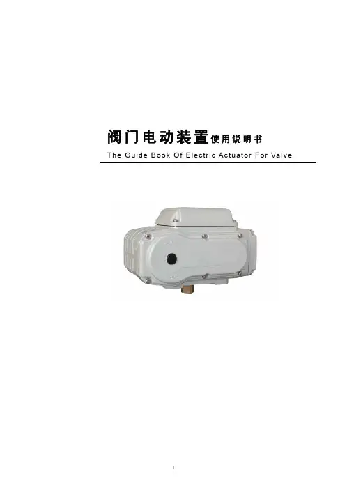
电动调节阀说明书电动调节阀说明书篇一:电动阀说明书1.概述多回转阀门电动装置,简称为Z型电装,是阀门实现开启、关闭或调节控制的驱动设备。
Z型电装适用于闸阀、截止阀、隔膜阀、柱塞阀、节流阀、水闸门等。
可用于明杆阀,也可用于暗杆阀。
本系列电装具有功能全、性能可靠、控制系统先进、体积小、重量轻、使用维护方便等特点。
可对阀门实行远控、集控和自动控制。
广泛用于电力、冶金、石油、化工、造纸、污水处理等行业。
本产品的性能符合JB/T8528-1997《普通型阀门电动装置技术条件》的规定。
隔爆型的性能符合GB3836.1-2000《爆炸性气体环境用电气设备第1部分:通用要求》,GB3836.2-2000《爆炸性气体环境用电气设备第2部分:隔爆型“d”》及JB/T8529-1997《隔爆型阀门电动装置技术条件》的规定。
多回转电动装置按防护类型分:有户外型和隔爆型;按控制方式分:有常规型、整体型和整体调节型;按连接型式分:有转矩型、电站型和推力型。
2.型号表示方法A:带现场按钮;F:带4-20mA信号输出;S:带手动减速箱Z:整体型;T:整体调节型输出轴最大转圈数:阿拉伯数字表示,无数字见表1 防护类型:W表示户外型;B表示隔爆型输出转速:阿拉伯数字表示,单位r/min(转/分)连接型式:T表示推力型,I表示电站型,无代号为常规转矩型额定输出转矩:阿拉伯数字表示,单位kgf2m 产品型式:多回转电动装置型号示例:1.Z30I-18W:多回转电动装置,输出转矩300N2m(30kgf2m),电站型接口,输出转速18r/min,最大转圈数60,常规户外型。
2.Z45T-24B/S:多回转电动装置,输出转矩450N2m(45kgf2m),推力型接口,输出转速24 r/min,最大转圈数120,隔爆型,带手动减速箱。
3.Z120-24W/240T:多回转电动装置,输出转矩1200N2m (120kgf2m),转矩型接口,输出转速24 r/min,最大转圈数240圈,整体调节型。
封面目录1、产品概述2、主要技术参数3、产品型号规格4、结构与原理5、安装6、调整7、外形尺寸8、配套支架9、故障和解决办法10、订货须知11、安全使用注意事项(1)(1)(2)(3)(7)(8)(11)(12)(13)(13)(14)使用本执行器时,请先认真阅读和理解本说明书,通过正确的使用和维护,充分发挥其效能。
1 产品概述3810L系列直行程电子式电动执行器有以 220V交流单相电源和 380V三相交流电源两种驱动电源的机型,接受来自调节器控制信号(D C4 ~ 20m A或D C1 ~ 5V),实现预定直线往复运动的新型执行器。
本系列执行器被用作调节阀的执行机构时,几乎具备了调节阀本身所要求的各种动作变换功能以及阀开度信号功能和手动功能。
因此被广泛应于发电、冶金、石化、轻工及环保等工业部门。
本系列执行器有以下主要特点:1.1 执行器设计有伺服系统(无需另配伺服放大器),只需接入D C4 ~ 20m A(或D C1 ~5V)信号和对应的电源即可工作。
内设接线端子,接线极为简单方便。
1.2 执行器的关键部件 — 控制器,采用最先进的混合集成电路,用树脂密封浇铸,外形为匣状,体积小,可靠性高。
1.3 驱动量的反馈检测采用高性能导电塑料电位器,分辨率< 0.4%。
1.4 具备自诊断功能,当发生故障时,控制器上的指示灯会立即发出指示信号。
1.5 用状态选择开关可以设定断信号时,(阀芯处于全开,全闭或自锁状态。
)1.6 用状态选择开关可以设定(正、反动作。
)1.7 用状态选择开关可以设定输入信号为(D C4~20m A或D C1~5V。
)1.8 调整工作零点(始点)和行程(终点)简单易行。
1.9 当突然断电时,能确保阀芯自锁。
1.10 采用同步皮带转动,有效降低了噪音。
1.11 延时保护功能,额定负载时,能实行状态自锁,故障发生时,能立即起动保护,并可反向运行取消延时保护。
2 主要技术参数2.1 电源单相A C220V±10%,50H z,三相A C380V±10%,50H z(需订货时注明)2.2 耗电功率(额定负载时)规格 A型执行器 50V A;规格 B 型执行器 150V A;规格 C 型执行器 220V A。
snna电动门说明书
一、用遥控器操作
1、开门按钮:门从任意状态开始开门运行,直到门全开,延时20秒后转关门运行,直到门全关。
2、开门按钮:门从任意状态开始关门运行,直到门全关。
3、停止按钮:门立即停在当前位置。
4、如果门在关门运行中前方有阻挡物,立即转成开门运行。
二、自动控制
1、门正常状态处于全关位置。
2、在任一票箱刷卡,立即启动开门运行,直到门全开,延时20秒后转关门运行,直到门全关。
3、无论门处于什么状态(包括关门运行、门全关或门停在某一位置),只要刷卡,立即转成开门运行。
4、如果门在关门运行中前方有阻挡物,立即转成开门运行。
三、门停在特定位置
1、门正常状态处于全关位置。
2、如果希望门停在特定位置,要用遥控器的停止按钮。
比如:希望门停在几乎全开的位置而不自动关门,则要在快要开到位或门刚从全开位置开始关门的时候,按遥控器的停止按钮,门会立即停止,并保持此状态。
3、要恢复正常工作状态,就按遥控器的开门或关门按钮,或者在任一票箱刷卡,门的运行就会转成自动控制的运行模式。