FEY FK6系列产品样本
- 格式:pdf
- 大小:1.04 MB
- 文档页数:9

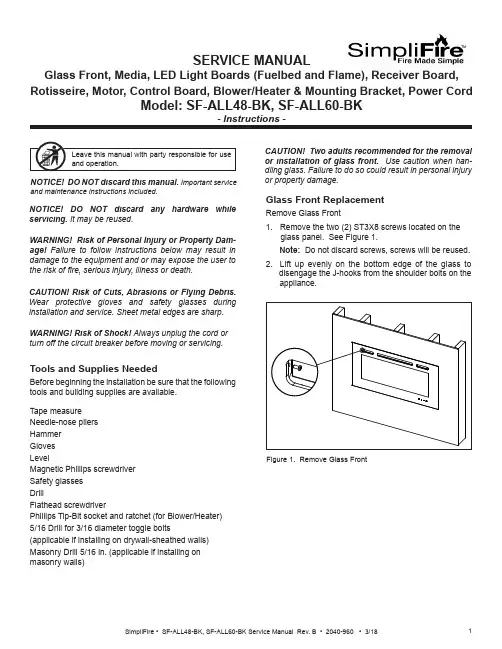
SERVICE MANUALGlass Front, Media, LED Light Boards (Fuelbed and Flame), Receiver Board, Rotisseire, Motor, Control Board, Blower/Heater & Mounting Bracket, Power CordCAUTION! Risk of Cuts, Abrasions or Flying Debris. Wear protective gloves and safety glasses duringinstallation and service. Sheet metal edges are sharp.NOTICE! DO NOT discard this manual. Important serviceand maintenance instructions included.NOTICE! DO NOT discard any hardware while servicing. It may be reused.WARNING! Risk of Shock! Always unplug the cord or turn off the circuit breaker before moving or servicing.Tools and Supplies NeededBefore beginning the installation be sure that the following tools and building supplies are available.Tape measure Needle-nose pliers Hammer Gloves LevelMagnetic Phillips screwdriver Safety glasses DrillFlathead screwdriverPhillips Tip-Bit socket and ratchet (for Blower/Heater)5/16 Drill for 3/16 diameter toggle bolts(applicable if installing on drywall-sheathed walls)Masonry Drill 5/16 in. (applicable if installing on masonry walls)Glass Front ReplacementRemove Glass Front1. Remove the two (2) ST3X8 screws located on theglass panel. See Figure 1. Note: Do not discard screws, screws will be reused. 2. Lift up evenly on the bottom edge of the glass to disengage the J-hooks from the shoulder bolts on the appliance.or property damage.Figure 1. Remove Glass FrontWARNING! Risk of Personal Injury or Property Dam-age! Failure to follow instructions below may result in damage to the equipment and or may expose the user to the risk of 昀椀re, serious injury, illness or death.Stone/Media Installation1. Remove Glass.2. Arrange the stone/media along the inset windowledge at the front of the appliance.Note: Extra media are provided and may bedistributed based on consumer preference. Not all media needs to be used.Glass Replacement (Continued)Installing Glass3. Install front panel. Locate the J-hooks on the back side of the glass on the four shoulder bolts on the appliance opening. Engage the shoulder bolts. See Figure 2.4. Press down on top edge of glass to fully engage J- hooks on the shoulder bolts.Note: Make sure the glass is fully attached to the 昀椀re-box so that the control panel can work properly.Figure 2. Glass Front Removal/Installation5. Thread the two (2) ST3X8 screws into the threaded holes on the glass panel. Check the alignment of the glass panel and securely tighten the screws. SeeFigure 3.Figure 3. Secure Glass Front1. Disconnect electrical service to the appliance. Forrecessed electrical installations that are hardwired,昀椀nd and shut-off service at the breaker. For wall-mounted installations that use a corded plug,disconnect the cord from the receptacle.2. Remove the glass front from the appliance. Use twopeople.3. Remove appliance the two screws in upper right andleft corners of the glass opening. Follow speci昀椀cinstructions from page 1 and 2 for removal of thefront glass. See Figure 4. CAUTION! Two adults recommended for the removal or installation of glass front. Use caution when han-dling glass. Failure to do so could result in personal injuryor property damage. Figure 4. Remove Upper Right & Left ScrewsPreparation for Component Installation4. Remove right and left side panels by turning thepanels inward. See Figure 5.Figure 5. Remove Right & Left Side Panels5. Using a 昀氀athead screwdriver, pry open the seventabs as shown in Figure 6. Pry the tabs upward at a30 degree angle. During this step, take care not toscratch or damage the glass panel behind the tabs.TABSFUELBED PLASTIC COVER Figure 6. Remove Plastic Cover6. Remove the fuelbed plastic cover that covers thefuelbed LED light strips. See Figure 6.LED Light Board InstallationThe LED Service Kit includes LED Light Boards for both the Fuelbed and the Flame effect.Determine which LED light set to be installed. See Figure 7.Figure 7. LED Light Board Identi昀椀cationLED FOR FUELBED1. Complete Steps 1-6 in Preparation for ComponentInstallation instructions. 2. Locate the Fuelbed LED Light Board cable. See Figure 8.LED LIGHT BOARD CABLE3. Unplug the LED Light Board cable. See Figure 9.LED LIGHT BOARD CABLEFigure 8. LED Light Board CableFigure 9. Unplug LED Light Board Cable4. Remove the LED light board from the bottom isolation columns. Starting at one end of the board use aLED FOR FLAMEFigure 10. Isolation Columns5. Remove and discard LED light board, replace with new LED light board. Install new LED light board by engaging the holes in the light board with the plastic barbs, and pressing into position. Reconnect the cables. See Figure 9.Fuelbed LED Light Board InstallationReceiver Board, Rotisseire, Motor, Flame LED Light Board, Control Board and Blower/ Heater Installation1. Complete Steps 1-6 in Preparation for ComponentInstallation instructions.3. Unplug Fuelbed LED Light Board, then lift it from theappliance set aside.Figure 12. Bracket Screw Location4. Remove seven (7) Phillips screws from the bracket. Remove the bracket. Set aside. See Figure 12.5. Carefully remove the glass panel. Rotate the top edge of the glass panel towards the opening, then lift out the the glass panel from the appliance. Set glass panel aside in a safe location, preferably a soft surface such as carpet or cardboard.Figure 11. Fuelbed LED Light Board Screw LocationReceiver Board Installation6. Locate the Receiver Board in the upper right side of appliance. See Figure 13.Figure 14. Receiver Board Cable7. Remove the Receiver Board from the isolationcolumns. Use a needle-nose pliers to compress the barbs on each isolation column.8. Unplug the cable, remove the Receiver Board and install with replacement board. See Figure 14.9. Reverse steps to complete installation.NOTE: The following steps (6-9) are only for re-placement of the Receiver Board.If replacing Rotisseire, Motor, Flame LED LightBoard, Control Board and/or Blower/Heater continue onto step 10.10. Remove two (2) Phillips screws at the bottom of the left and right side of the appliance opening. See11. Remove 14 Phillips screws at the top and bottom of the 昀氀ame screen. See Figure 16.12. Remove the 昀氀ame screen.Note: Be sure to place on a 昀氀at surface with the silk screen face-up. This is to prevent any distortion on the screen.13 Remove the center screw located in the the center of the Rotisseire. See Figure 17.14. Pull the Rotisseire to the left to disengage it from the motor, then remove the Rotisseire assembly.Figure 16. Flame Screen LocationFigure 17. Rotisseire Screw LocationIf replacing only the Rotisseire, install replacement part and reverse the installation steps.Be sure the 昀氀ame screen is installed correctly with the 昀氀ame silk screen to the outside and 昀氀ames at the bottom of the appliance.If replacing Motor continue to the next steps 15-18.Rotisseire InstallationIf replacing Flame LED Light Board continue to step 19.CAUTION! Risks of Cuts! Rotisseire has sharp edgesMotor InstallationThe motor is located in the lower right corner of the appliance.15. Remove the rubber shaft on the motor. See Figure 18.Figure 18. Rubber Shaft RemovalRUBBER SHAFT16. Remove the two screws on the motor. See Figure 19.Figure 19. Remove Motor Screws17. Unplug the motor cable connection. See Figure 20.Figure 20. Unplug Motor Cable18. Install replacement part and reverse the installation steps.Flame LED Light Board InstallationNOTE: The following steps (15-18) are only for re-placement of the motor.If replacing Flame LED Light Board, continue onto step 19.19. Remove screws used to attach the 昀氀ame screenFigure 21. Remove Flame Screen Bracket Screws.20. Remove 昀氀ame screen bracket.21. Unplug cable connection on each end of the LED Board. See Figure 22.Figure 22. Unplug LED Board Cable Connections22. Install replacement part and reverse the installation steps.Control Board Installation23. Remove the two (2) Phillips screws. After removing screws the mounting bracket can be lowered downto access the wires. See Figure 23.Figure 23. Remove Mounting Bracket Screws24. Unplug the 昀椀ve (5) pin and socket connectors between the Control Board and the wire harnesses. Tag and label the wire harnesses to ensure that wires will be reconnected correctly. See Figure 24.Figure 24. Unplug Control Board25. Install new Control Board and reverse the installation steps. Blower/Heater Installation26. Locate the four (4) screws on the mounting plate for the blower/heater module. See Figure 25.27. Remove the four (4) Phillips screws.Figure 25. Remove Mounting Plate Screws28. Drop the Blower/Heater module down on the shelf. See Figure 26.29. Reach up into the right end of the slot, and unplug the cable from the connector.Figure 26. Remove Blower/Heater30. Install new Blower/Heater and reverse the installationsteps.SHELFMasonry Wall •In the marked locations, drill 5/16 in. diameter x 2 in. deep holes. See Figure 30.• Insert the provided wall anchors into the holes. •Gently tap the anchors with a hammer until they are 昀氀ush with the wall surface.•With mounting hooks pointed up, attach the bracket to the masonry anchors with ST5X40 screws . SeeFigure 31.Figure 29. Installing Anchors in Hollow WallFigure 28. Toggle Bolt Installation through Mounting BracketFigure 30. Masonry Anchor PlacementFigure 27. 3/16 Toggle-Bolt Anchor•The toggle-bolt anchors are provided to accomodate the required anchor points based on the appliance. Use of toggle bolt anchors requires drywall thick-ness of minimum 1/2 in. and drilled holes size of 5/16 in. diameter.•Insert the bolt through the front side of the mounting bracket and thread the toggle onto it from the rear of the bracket. See Figure 28.•Fold the toggle wings 昀氀ush against the bolt and push them through a drilled hole until the toggle wings expand open on the other side. See Figure 29. •Pull back on the bolt and tighten. See Figure 29.Note: This product cannot be installed on a wall sheathed with drywall less than 1/2 in. thick, unless all six (6) anchor points in the mounting bracket align with structural framing members.WARNING! Risk of Damage or Personal Injury! Al-lowable pull-out and shear strength are 25% of ultimate values or less, as required by building authorities.Framed Wall •Locate the mounting bracket on the wall in thedesired location of the appliance. Level the bracket, then mark its location on the wall, including a mark-ing for each of the fastener holes in the bracket. •For each of the marked mounting point locations, determine which points align with a structural fram-ing member.•At the points where a wood or metal framing mem-ber exists, the ST5X40 screw can be installed directly into that structural member.•For every mounting hole that does not align with a structural framing member, a wall board toggle-bolt anchor must be used. See Figure 27.Direct Wall Mounting with Wall Mounting BracketThe wall mounting bracket can be installed on masonry walls such as those constructed of brick or concrete, or to framed walls constructed of wood or steel framing sheathed with gypsum wallboard, drywall, wood, etc. The method used to mount the mounting bracket is dif-ferent between masonry walls and framed walls. Refer to the following sections for more detail on the method applicable to this installation.11SimpliFire • SF-ALL48-BK, SF-ALL60-BK Service Manual Rev. B • 2040-960 • 3/18SimpliFire, a brand of Hearth & Home Technologies7571 215th Street West, Lakeville, MN 55044Please contact the SimpliFire customer/technical support hotline at 877-320-0730 with any questions or concerns.WARNING! Risk of Damage or Personal Injury! Do not use supplied masonry anchors on hollow walls,sheathed with wood, gypsum wallbaord, drywall or other materials.Figure 31. Bracket AttachmentWARNING! Risk of Fire, Electrical Shock and Injury! Ensure the power cord is not installed so that it is pinched or against a sharp edge and ensure that the power cord is stored or secure to avoid tripping and snagging.Power Cord Kit InstallationThe appliance power cord has a three pin NEMA-5-15P plug. The power cord should not be used unless a grounded receptacle is available.1. Remove the terminal block cover plate located on the right end of the appliance.2. Disconnect the terminal block from the three wires inside the appliance. Discard the terminal block cover plate.3. Connect the three appliance wires to the terminal block supplied with the power cord kit. See Figure 32.4. Replace cord kit terminal block cover plate and retaining screws. Plug cord into nearest outlet.Figure 32. Optional Power Cord Assembly InstallationLNR E DB L U EWire DiagramY E L L O W / G R E E N。
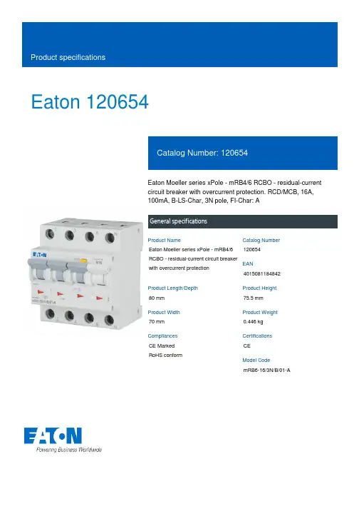
Eaton 120654Eaton Moeller series xPole - mRB4/6 RCBO - residual-current circuit breaker with overcurrent protection. RCD/MCB, 16A, 100mA, B-LS-Char, 3N pole, FI-Char: AGeneral specificationsEaton Moeller series xPole - mRB4/6 RCBO - residual-current circuit breaker with overcurrent protection120654401508118484280 mm 75.5 mm 70 mm 0.446 kg CE Marked RoHS conformCE mRB6-16/3N/B/01-AProduct NameCatalog Number EANProduct Length/Depth Product Height Product Width Product Weight Compliances Certifications Model CodeSwitchgear for residential and commercial applicationsmRB6Combined RCD/MCB devicesSwitchgear for industrial and advanced commercial applications Three-pole + N44BB16 A6 - 25 Ampere0.1 AType A, pulse-current sensitiveRCBO AC400 V230 V / 400 V400 V500 V4 kV30, 100, 300 MilliAmpere Partly surge-proof, 250 A 50 HzA6 kA6 kA6 kA0.5 x I∆n6 kA6 kA6 kAApplicationProduct rangeBasic functionProduct applicationNumber of polesNumber of poles (protected) Number of poles (total) Tripping characteristic Release characteristicRated currentRated current of product range Fault current rating Sensitivity typeType Voltage typeVoltage ratingVoltage rating at ACRated operational voltage (Ue) - maxRated insulation voltage (Ui)Rated impulse withstand voltage (Uimp)Rated fault currents of product rangeImpulse withstand currentFrequency ratingLeakage current typeRated switching capacityRated switching capacity (IEC/EN 60947-2)Rated switching capacity (IEC/EN 61009)Rated non-tripping currentRated short-circuit breaking capacity (EN 60947-2) Rated short-circuit breaking capacity (EN 61009) Rated short-circuit breaking capacity (EN 61009-1) Rated short-circuit breaking capacity (IEC 60947-2)0 kA 0.25 kAUndelayed Non-delayed 100 Ampere gL 3III245 mm480 mm70 mmTri-stable slide catch - enables removal from existing busbar combinationIP20IP40Twin-purpose1 - 25 Square MillimeterBusbar tag shroud to VBG41 mm²25 mm²1 mm²25 mm²2 mmIEC 68-2: 25 °C - 55 °C at 90 % - 95 % humiditySurge current capacityDisconnection characteristic TrippingBack-up fuseSelectivity class Overvoltage category Pollution degree FrameWidth in number of modular spacingsDevice heightBuilt-in depthMounting styleDegree of protectionDegree of protection (built in)Terminals (top and bottom)Solid terminal capacitiesTerminal protectionConnectable conductor cross section (solid-core) - min Connectable conductor cross section (solid-core) - max Connectable conductor cross section (multi-wired) - min Connectable conductor cross section (multi-wired) - max Material thicknessClimatic proofing16 A0 W 11.6 W 0 W0 W-25 °C 40 °C Meets the product standard's requirements.Meets the product standard's requirements.Meets the product standard's requirements.Meets the product standard's requirements.Meets the product standard's requirements.Does not apply, since the entire switchgear needs to be evaluated.Does not apply, since the entire switchgear needs to be evaluated.Meets the product standard's requirements.Does not apply, since the entire switchgear needs to be evaluated.Meets the product standard's requirements.Does not apply, since the entire switchgear needs to be evaluated.Does not apply, since the entire switchgear needs to be evaluated.Is the panel builder's responsibility.Is the panel builder's responsibility.Is the panel builder's responsibility.Rated operational current for specified heat dissipation (In) Heat dissipation per pole, current-dependentEquipment heat dissipation, current-dependentStatic heat dissipation, non-current-dependentHeat dissipation capacityAmbient operating temperature - minAmbient operating temperature - max 10.2.2 Corrosion resistance10.2.3.1 Verification of thermal stability of enclosures10.2.3.2 Verification of resistance of insulating materials to normal heat10.2.3.3 Resist. of insul. mat. to abnormal heat/fire by internal elect. effects10.2.4 Resistance to ultra-violet (UV) radiation10.2.5 Lifting10.2.6 Mechanical impact10.2.7 Inscriptions10.3 Degree of protection of assemblies10.4 Clearances and creepage distances10.5 Protection against electric shock10.6 Incorporation of switching devices and components10.7 Internal electrical circuits and connections10.8 Connections for external conductors10.9.2 Power-frequency electric strengthIs the panel builder's responsibility.Is the panel builder's responsibility.The panel builder is responsible for the temperature rise calculation. Eaton will provide heat dissipation data for the devices.Is the panel builder's responsibility. The specifications for the switchgear must be observed.Is the panel builder's responsibility. The specifications for the switchgear must be observed.The device meets the requirements, provided the information in the instruction leaflet (IL) is observed.3Concurrently switching N-neutralIEC/EN 61009eaton-xpole-mrb4-rcbo-catalog-ca019058en-en-us.pdfeaton-xpole-mrb6-rcbo-catalog-ca019057en-en-us.pdfDA-DC-03_mRB-3N03_mRB-3p_20041603_mRB-3N_281118eaton-mcb-xpole-mrb4-6-characteristic-curve.epseaton-xeffect-frbm6/m-characteristic-curve-002.jpgDimensions xPole mRB4/mRB6 3Neaton-xeffect-frbm6/m-dimensions-004.jpgeaton-mcb-xpole-mrb4-6-dimensions.eps3D Drawing xPole mRB4/mRB6 3Neaton-xpole-combined-mcb-rcd-device-rcbo-packaging-manual-multilingual.pdfIL019140ZUDA-CS-faz_3pn_4pDA-CD-faz_3pn_4pCharacteristics xPole mRB4/mRB6 3Neaton-mcb-xpole-mrb4-6-wiring-diagram.epsContact Sequence xPole mRB4/mRB6 3N10.9.3 Impulse withstand voltage10.9.4 Testing of enclosures made of insulating material 10.10 Temperature rise10.11 Short-circuit rating10.12 Electromagnetic compatibility10.13 Mechanical function Current limiting class FeaturesStandards Catalogues Certification reports Characteristic curve DrawingsInstallation instructions mCAD modelTime/current curves Wiring diagramsEaton Corporation plc Eaton House30 Pembroke Road Dublin 4, Ireland © 2023 Eaton. All rights reserved. Eaton is a registered trademark.All other trademarks areproperty of their respectiveowners./socialmediaeaton-xeffect-frbm6/m-wiring-diagram-002.jpg。

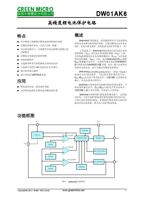
FK6-1000型加弹机培训教材XX有限公司员工培训教材(试行)第一节:FK6-1000型加弹机的构造及功能简介第二节:加弹生产知识介绍第三节:加弹机维修保养知识介绍第四节:加弹生产工艺举例说明第五节:结束语:我所面临的使命第一节:FK6-1000型加弹机的构造及功能简介1、喂丝罗拉喂丝罗拉的作用是实现丝条的传输作用。
喂丝装置有两种组成方法。
即1):喂丝罗拉与皮辊型;2)喂丝罗拉与皮圈型。
其中喂丝罗拉为主动轴,表面镀铬抛光;皮圈(或皮辊)靠弹簧的加压压在喂丝罗拉上,为从动型。
2、喂丝罗拉前的横动移丝器它的作用是避免丝条对罗拉的集中磨损,延长皮圈(或压辊)的使用寿命。
生产加弹丝时,移丝间距一般为5-10mm。
移丝位置不正时,不能保证丝条在喂丝皮圈(或压辊)的规定范围内运行,从而不能保证丝条按规定的工艺要求执行。
如一、二罗拉前横动移丝器位置不正,就不能保证丝条正常牵伸的实现,引起缠丝。
3、第一加热器第一加热器又叫变型热箱,是接触式加热方式,1000M型长为2.5m,V型长为2.0m.。
其作用是加热丝条呈塑化状态,降低拉伸变形应力。
第一热箱温度提高,纤维的卷曲性和膨松性提高,染色变浅。
在实际生产中,我们必须经常地检查热箱的丝道,并每隔2-3个月要进行一次清洁。
因为一热箱温度的高低直接影响丝的卷曲性、膨松性。
进而影响染色性能。
故生产中丝越偏离热箱丝道,则变形丝条越差,染色等级越低。
如果大部分或完全跑出丝道,则成品丝将成僵丝。
4、冷却板冷却板的作用是对纤维在加捻以后卷曲结构的固定,如果冷却不佳(或不均匀),则纤维在加捻过程形成的卷曲结构就不均匀,进而影响染色均匀性,导致染色降等。
加弹机的丝条冷却用冷却板冷却。
5、假捻器假捻器的作用是产生机械扭曲应力,以便变形加工。
它是加弹机的核心。
6、第二罗拉(中间罗拉)中间罗拉很重要,通常它的速度即所谓的车速。
要求它的皮圈架握持力要强,防止逃捻丝的发生。
7、第二加热器第二加热器又叫定型热箱,是非接触式。

V2416A SeriesCompact,fanless,vibration-proof computers for rolling stock applicationsFeatures and Benefits•Intel Celeron/Core i7processor•Two hot-swappable2.5-inch HDD or SSD storage expansion trays•Dual independent DVI-I displays•2Gigabit Ethernet ports with M12X-coded connectors•2CFast sockets for OS backup•M12A-coded power connector•Compliant with EN50121-4•Complies with all EN50155mandatory test items1•IEC61373certified for shock and vibration resistance•Ready-to-run Debian7,Windows Embedded Standard7,and Windows10Embedded IoT Enterprise2016LTSB platforms•-40to70°C wide-temperature models available•Supports SNMP-based system configuration,control,and monitoring(Windows only)CertificationsIntroductionThe V2416A Series embedded computers are based on the Intel3rd Gen processor and feature4RS-232/422/485serial ports,dual LAN ports,and 3USB2.0hosts.In addition,the V2416A computers provide dual DVI-I outputs and comply with the mandatory test items of the EN50155 standard,making them suitable for a variety of industrial applications.The CFast socket,SATA connectors,and USB sockets provide the V2416A computers with the reliability needed for industrial applications that require data buffering and storage expansion.Most importantly,the V2416A computers come with2hot-swappable storage trays for inserting additional storage media,such as hard disk or solid-state drives,and support hot swapping for convenient,fast,and easy storage replacement. Each storage tray has its own LED to indicate whether or not a storage module is plugged in.The V2416A Series computers come preinstalled with a choice of Linux Debian7or Windows Embedded Standard7to provide programmers with a familiar environment in which to develop sophisticated,bug-free application software at a low cost.1.This product is suitable for rolling stock railway applications,as defined by the EN50155standard.For a more detailed statement,click here:/doc/specs/EN_50155_Compliance.pdfAppearanceFront View Rear ViewSpecificationsComputerCPU V2416A-C2Series:Intel®Celeron®Processor1047UE(2M cache,1.40GHz)V2416A-C7Series:Intel®Core™i7-3517UE Processor(4M cache,up to2.80GHz) System Chipset Mobile Intel®HM65Express ChipsetGraphics Controller Intel®HD Graphics4000(integrated)System Memory Pre-installed4GB DDR3System Memory Slot SODIMM DDR3/DDR3L slot x1Supported OS Linux Debian7Windows Embedded Standard7(WS7E)32-bitWindows Embedded Standard7(WS7E)64-bitStorage Slot CFast slot x2Computer InterfaceEthernet Ports Auto-sensing10/100/1000Mbps ports(M12X-coded)x2Serial Ports RS-232/422/485ports x4,software selectable(DB9male)USB2.0USB2.0hosts x1,M12D-coded connectorUSB2.0hosts x2,type-A connectorsAudio Input/Output Line in x1,Line out x1,M12D-codedDigital Input DIs x6Digital Output DOs x2Video Input DVI-I x2,29-pin DVI-D connectors(female)Digital InputsIsolation3k VDCConnector Screw-fastened Euroblock terminalDry Contact On:short to GNDOff:openI/O Mode DISensor Type Dry contactWet Contact(NPN or PNP)Wet Contact(DI to COM)On:10to30VDCOff:0to3VDCDigital OutputsConnector Screw-fastened Euroblock terminalCurrent Rating200mA per channelI/O Type SinkVoltage24to40VDCLED IndicatorsSystem Power x1Storage x1Hot-swappable2LAN2per port(10/100/1000Mbps)Serial2per port(Tx,Rx)Serial InterfaceBaudrate50bps to921.6kbpsFlow Control RTS/CTS,XON/XOFF,ADDC®(automatic data direction control)for RS-485,RTSToggle(RS-232only)Isolation N/AParity None,Even,Odd,Space,MarkData Bits5,6,7,8Stop Bits1,1.5,2Serial SignalsRS-232TxD,RxD,RTS,CTS,DTR,DSR,DCD,GNDRS-422Tx+,Tx-,Rx+,Rx-,GNDRS-485-2w Data+,Data-,GNDRS-485-4w Tx+,Tx-,Rx+,Rx-,GNDPower ParametersInput Voltage12to48VDCPower Connector M12A-coded male connectorPower Consumption(Max.) 3.3A@12VDC0.82A@48VDCPower Consumption40W(max.)Physical CharacteristicsHousing AluminumIP Rating IP30Dimensions(with ears)250x86x154mm(9.84x3.38x6.06in)Dimensions(without ears)275x92x154mm(10.83x3.62x6.06in)Weight4,000g(8.98lb)Installation DIN-rail mounting(optional),Wall mounting(standard) Protection-CT models:PCB conformal coating Environmental LimitsOperating Temperature Standard Models:-25to55°C(-13to131°F)Wide Temp.Models:-40to70°C(-40to158°F) Storage Temperature(package included)-40to85°C(-40to185°F)Ambient Relative Humidity5to95%(non-condensing)Standards and CertificationsEMC EN55032/24EMI CISPR32,FCC Part15B Class AEMS IEC61000-4-2ESD:Contact:6kV;Air:8kVIEC61000-4-3RS:80MHz to1GHz:20V/mIEC61000-4-4EFT:Power:2kV;Signal:2kVIEC61000-4-5Surge:Power:2kVIEC61000-4-6CS:10VIEC61000-4-8PFMFRailway EN50121-4,IEC60571Railway Fire Protection EN45545-2Safety EN60950-1,IEC60950-1Shock IEC60068-2-27,IEC61373,EN50155Vibration IEC60068-2-64,IEC61373,EN50155DeclarationGreen Product RoHS,CRoHS,WEEEMTBFTime332,173hrsStandards Telcordia(Bellcore),GBWarrantyWarranty Period3yearsDetails See /warrantyPackage ContentsDevice1x V2416A Series computerInstallation Kit8x screw,for storage installation2x storage key1x wall-mounting kit8x washer,for HDD/SSDDocumentation1x document and software CD1x quick installation guide1x warranty cardDimensionsOrdering InformationModel Name CPU Memory(Default)OS CFast(CTO)Backup CFast(CTO)Hot-SwappableSSD/HDD Tray(CTO)Operating Temp.ConformalCoatingV2416A-C2Celeron1047UE4GB or optional1(Optional)1(Optional)2(Optional)-25to55°C–V2416A-C2-T Celeron1047UE4GB or optional1(Optional)1(Optional)2(Optional)-40to70°C–V2416A-C2-CT-T Celeron1047UE4GB or optional1(Optional)1(Optional)2(Optional)-40to70°C✓V2416A-C7i7-3517UE4GB or optional1(Optional)1(Optional)2(Optional)-25to55°C–V2416A-C7-T i7-3517UE4GB or optional1(Optional)1(Optional)2(Optional)-40to70°C–V2416A-C7-CT-T i7-3517UE4GB or optional1(Optional)1(Optional)2(Optional)-40to70°C✓V2416A-C2-W7E Celeron1047UE4GB8GB1(Optional)2(Optional)-25to55°C–V2416A-C2-T-W7E Celeron1047UE4GB8GB1(Optional)2(Optional)-40to70°C–V2416A-C7-T-W7E Core i7-3517UE4GB8GB1(Optional)2(Optional)-40to70°C–Accessories(sold separately)Battery KitsRTC Battery Kit Lithium battery with built-in connectorCablesCBL-M12XMM8PRJ45-BK-100-IP67M12-to-RJ45Cat-5E UTP gigabit Ethernet cable,8-pin X-coded male connector,IP67,1mCBL-M12(FF5P)/Open-100IP67A-coded M12-to-5-pin power cable,IP67-rated5-pin female M12connector,1mConnectorsM12A-5PMM-IP685-pin male circular threaded D-coded M12USB connector,IP68M12X-8PMM-IP678-pin male X-coded circular threaded gigabit Ethernet connector,IP67M12A-5P-IP68A-coded screw-in sensor connector,female,IP68,4.05cmM12A-8PMM-IP678-pin male circular threaded A-codes M12connector,IP67-rated(for field-installation)Power AdaptersPWR-24270-DT-S1Power adapter,input voltage90to264VAC,output voltage24V with2.5A DC loadPower CordsPWC-C7AU-2B-183Power cord with Australian(AU)plug,2.5A/250V,1.83mPWC-C7CN-2B-183Power cord with two-prong China(CN)plug,1.83mPWC-C7EU-2B-183Power cord with Continental Europe(EU)plug,2.5A/250V,1.83mPWC-C7UK-2B-183Power cord with United Kingdom(UK)plug,2.5A/250V,1.83mPWC-C7US-2B-183Power cord with United States(US)plug,10A/125V,1.83mAntennasANT-WDB-ANF-0407 2.4/5GHz,omni-directional antenna,4/7dBi,N-type(male)Wall-Mounting KitsV2400Isolated Wall Mount Kit Wall-mounting kit with isolation protection,2wall-mounting brackets,4screwsDIN-Rail Mounting KitsDK-DC50131DIN-rail mounting kit,6screws©Moxa Inc.All rights reserved.Updated Jun12,2019.This document and any portion thereof may not be reproduced or used in any manner whatsoever without the express written permission of Moxa Inc.Product specifications subject to change without notice.Visit our website for the most up-to-date product information.。

MX+OFWY6 无源型分励+辅助使用说明书安装、使用产品前,请仔细阅读使用说明书,并妥善保管备用。
安全告知在安装、操作、运行、维护、检查之前,请务必认真阅读本说明书,并按照说明书上的内容准确安装、使用本产品。
危险:●严禁湿手操作辅助触头和分励触头;●使用中,严禁触摸导电部位;●维护与保养时,必须确保产品不带电;●严禁用短路的办法来测试产品;注意:●安装、维护与保养时,应由具有专业资格的人员操作;●产品的各项特性出厂时已整定,使用中不能自行拆装或随意调节;●使用前请确认产品工作电压、额定电流、频率及特性是否符合工作要求;●为防止相间短路,应对接线端裸露导线或铜母线进行绝缘处理;●如果产品在开箱时有破损或异常响声,应立即停止使用并联系供应商;●产品报废时,请做好产业废弃物处理,谢谢您的合作;目录1主要用途及适用范围 (1)2产品介绍 (1)2.1面板介绍 (1)2.2产品型号介绍 (2)3正常使用、安装及运输条件 (2)3.1使用、安装条件 (2)3.2贮存、运输条件 (2)4技术特性 (2)4.1主要技术参数 (2)5外形及安装尺寸 (3)5.1外形及安装尺寸见下图 (3)5.2接线图示意 (3)6安装和使用维护 (4)6.1安装 (4)6.2维护与保养 (4)7开箱检查 (5)8公司承诺 (5)1主要用途及适用范围MX+OFWY6主要与CDB6系列断路器进行拼装,实现远距离操作控制。
2产品介绍2.1面板介绍说明:1公司商标6扭矩、剥线指示2产品名称7敲落孔盖3额定电压8技术参数4接线端子指示9二维码5拼装示意图2.2产品型号介绍设计序号无源型分励+辅助代号3正常使用、安装及运输条件3.1使用、安装条件a)周围空气温度上限不超过+70℃, 下限不低于-35℃,并且在24小时内平均温度不超过+35℃;b)安装地点的海拔不超过2000m;c)温度为+40℃时,空气的相对湿度不超过50%;在较低温度下允许有较大的相对湿度,例如在+20℃时,相对湿度不超过90%,对于温度变化偶尔产生凝露应采取特殊的保护措施;d)安装在无爆炸危险的介质中,且介质中无足以腐蚀金属和破坏绝缘的气体与尘埃;e)安装在无显著冲击振动及无雨雪侵袭的地方;f)污染等级:2级;g)安装类别:Ⅱ类、Ⅲ类;h)防护等级:IP20;3.2贮存、运输条件a)温度下限不低于-40℃,上限不超过+70℃;b)相对湿度(25℃)不超过95%;c)产品在运输过程中应轻搬轻放,不应倒放,应尽量避免剧烈碰撞;4技术特性4.1主要技术参数基本参数额定绝缘电压(Ui):500V;额定冲击耐受电压:2.5KV;额定频率:50/60Hz;主要性能指标(1)触头使用类别:AC12、DC12;(2)分励控制电压:AC:100-415V/DC:110-130V;AC/DC:24V/48V;AC/DC:12V/24V;5外形及安装尺寸5.1外形及安装尺寸下图外形及安装尺寸5.2 接线示意图6安装和使用维护6.1安装a)安装前先检查产品标志与所使用的的条件是否相符;b)无源型分励+辅助脱扣器拼装在断路器左侧:附件拼装总宽54mm内,从左至右的顺序及数量:OF6/FF6/FS6/SD6(3 max.)+MO6/MV6/MN6/MVMN6/MSN6/MOWY6(2 max.)+MCB;c)无源型分励+辅助脱扣器左侧拼装产品时,需在拼装前去除敲落孔盖(面板介绍图7处);d)将脱扣器合、分几次检查操作机构有无卡滞现象,机构动作是否可靠;e)安装方式:采用TH35-7.5型安装轨;f)与CDB6i、CDB6LEi、CDB6Pi、CDB6PLEi、CDBK、CDBLEK、CDBKPLE等型号小型断路器配装使用,实现远距离操作控制;6.2维护与保养a)维护与保养时,必须由具有专业资格的人员操作;b)必须确保产品不带电;c)在正常操作条件下每年维护与保养一次,维护内容见表5:表5 维护与保养7开箱检查用户开箱后必须检查产品是否完好无损,外露金属是否生锈,是否因运输和保管不善造成产品有所缺陷,如有上述现象,产品则不能使用,请及时与供应商联系解决。
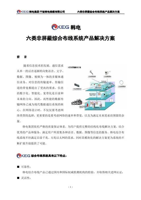
韩电六类非屏蔽综合布线系统产品解决方案前言随着信息技术的发展,通信需求从单一的话音逐渐转向集语音、文字、数据、图像、视频为一体的多媒体通信业务,对信息的传输速率、传输信道的带宽都提出了更高的要求,信息的数字化、智能化、宽带化是目前和未来的方向。
因此,高性能的数据传输网络已成为现代数据通信系统的核心。
在网络设计时,不仅仅要考虑网络类型的选择,更重要的是要考虑网络的速率和带宽,以及为满足未来需求而预留的余量。
韩电集团依托严格的质量保证体系,为用户提供完整的结构化布线解决方案,结合优秀的产品和服务,满足用户所需集各种语音、数据、图像等信息的服务。
韩电综合布线系统不但满足目前千兆、万兆以太网的需求,同时其模块化的解决方案更为系统的不断扩展升级提供了可能。
综合布线系统具有以下特点:■可靠性:韩电综合布线产品已通过国内和国际权威检测机构的检验,并取得相关进网认证;■灵活性:韩电综合布线系统中任何信息点都能连接不同类型的终端设备,当设备数量和位置发生变化时,只需采取简单的插接方式,实用方便,其灵活性和适应性都较强、且节省工程投资;■开放性:韩电综合布线系统对上层网络供应商是开放的,可支持不同网络厂家的产品及系统;韩电综合布线系统对同层综合布线系统厂家是开放的,可随意与不同系统厂家的产品搭配,组建完整的布线网络;■产品规格多样性:韩电综合布线产品的种类有——应用于室内或室外布线,具有UTP、FTP、SFTP结构的CAT.3、CAT.5、CAT.5E、CAT.6数字电缆以及相应的各类连接硬件,完全满足大部分布线系统的需求。
韩电CAT.6六类非屏蔽综合布线系统产品解决方案1、韩电单口/双口面板产品特性:韩电插座面板秉承了实用、人性化的设计风格,弧面亚光型结构美观大方,乳白色调可配合任意墙面风格;同时采用两片式设计,安装灵活方便、巧妙地隐藏了面板的安装螺丝孔;配合机械弹簧式防尘盖和标准标示系统,在国标86型面板外形体系上为用户提供了单口、双口可选型号,外形尺寸均为86*86mm,可安装系列超五类RJ45模块、电话模块等,符合国标安装要求,满足数据及语音应用。

F660 Limiting AmplifierOperating ManualOverview:The Fredenstein F660 Limiting Amplifier is a valve (tube) based compressor and limiter with the same very short signal path as the famous Fairchild 660/670. it uses the exact type of tubes, the 6386 LGP, as the Fairchild. Fortunately, new production tubes are available today, since original tubes are hardly available anymore. The four tubes form a single stage push-pull Class A amplifier and the whole signal path consists only of an T-type input attenuator, input transformer, Class A amplifier and finally an output transformer. At this point the similarities end. The F660 uses a DSP to control the operating points of the tubes, guarantying perfect working conditions all the time. The side chain amplifier is designed with semi-conductor components since it “only” generates the control voltage for the tubes. The final result is a compressor with the compression characteristics of the Fairchild, but with an extended frequency response, lower noise and lower distortion. The perfect buss compressor for today's high resolution audio. Since this a “Variable-Mu” type of compressor the relationship between anode currents and compression is almost quadratic, causing the anode currents to be very small at high compression rate. As with all “Variable-Mu” is not advised to go beyond10dB of compression since audible distortion will be present.Setting compression to around 5 dB yields the best results.Installation:Located on he front panel, there are the LCD display, the rotary control button, the output level meter and the gain reduction meter.Fig. 1F660 Front PanelOn the rear panel, there are the XLR connectors for MAIN INPUT, MAIN OUTPUT, SIDECHAIN INPUT and SIDECHAIN OUTPUT, as well as the RJ11 LINK Connectors, the IEC MAINS POWER connector, MAINS SWITCH, and most importantly the MAINS VOLTAGE SELECTOR. Please select your local mains voltage first before connecting to power!For basic operations,only the MAIN INPUT,MAIN OUTPUT and,of course,the MAINS POWER have to be connected. The SIDECHAIN INPUT and SIDECHAIN OUTPUT can be used to insert filters and other equipment into the side chain. In case of using several F660s the supplied link cable (RJ11) should be used to link all the units. Both link connector are identical and it does not matter which one is used.Fig. 2F660 Rear PanelOperations:After turning on the MAINS SWITCH on the rear panel, the unit performs a self test and after successful completion you will see the following screen:At this point the unit is in stand-by mode and the audio circuitry and the tubes are still powered-off, the unit is in bypass mode, but the output meter is connected to the main output. This allows the user to measure the level even in bypass mode.To turn the F660 on, please push the rotary control. The F660 will power up and go through a tube calibration cycle. During this cycle you will see the anode currents in both halves of the push-pull Class A amplifier.After the currents settled, the unit is fully operational and the user will be forwarded to the main menu.The Main Menu allows to modify the following parameters:Compressor Gain:The gain of the compressor without gain reduction can be adjusted in 0.5dB steps in the range of -11db and +11 dB. To adjust the gain move the cursor with the rotary control to the gain field and then press the rotary control.The cursor will move from the left to the right and the rotary control becomes the level “pot”. The change is applied immediately, therefore the engineer can hear the changes right away. Whensatisfied with the gain, push the rotary control again and the cursor will move back to the gain field and can be moved down to select different items.This procedure applies to all parameter adjustmentsCompression AC Threshold:The compression AC threshold determines at which level the compressor activates. Please note it is displayed in dBu not in the standard U.S. studio level of +4 dBu. This allows to easier match the maximum input of A/D converters almost always specified in dBu.Compression Ratio:This parameter determines the“strength”of the compression,higher numbers indicate more compression. It is the relationship between output level and input level if the output level is above the AC threshold.Ti m e Constant:The F660 employs the same 6 different time constants as the original Fairchild 660/670. Number one is the fastest and shortest and number 6 is the slowest and longest. Number 3 is always a good starting point.Fast Attack:The attack time can be changed in all 6 time constants by selecting faster attack times. Since the Fairchild time constants are more than simple integrating filters, it is impossible to set a value for this parameters. The actual attack is a combination of the selected time constant and the selected fast attack mode.DC Threshold:The Fairchild 660/670 has a fixed DC threshold of 2 volts. The F660 allows the user to select between 0.5 and 5 volts. Lower values result in stronger compression. The 2 volt setting is the default and used to reference the AC threshold.Bypass:If bypass is turned on, the main input and outputs are connected and the F660 is taken out of the signal pass. This is very useful for comparisons of the direct and compressed sounds.Side Chain:If Side Chain is set to ON, the side chain input is activated and the side chain is disconnected from the output. Inserting a high-pass filter between the side chain output and input can be used to avoid compression in unwanted frequency ranges. An example is using a high pass filter to form an de-esser.Link:This enables the multi-channel link capability. Please note that is feature has to be turned on on all participating units.Sub-Menus:There are three sub menus available to adjust the following parameters:Meter:Output Meter adjustmentsUtilities:Safe/Recall Parameters, Calibration etc.Meter Sub Menu:After selecting the meter menu on the main menu page the screen below will be displayed.Meter Range:The meter range of the peak meter can be switched between 60dB (one LED per dB) and 30dB (one LED per 0.5dB). In the 60dB setting the overall range is from -39dB to +20dB, in the 30dB setting from -24.5dB to + 5dB.Meter Hold :The peak hold time can be selected between 0s, 2.5s and indefinitely. In the 0s setting no peak hold is performed and in the indefinitely setting the user has to manually reset the hold value by selecting a different hold time.Meter Mode:The meter is capable to display peak and RMS values. The two modes are peak only as a bar graph or peak and ppm displayed simultaneously. In this case the PPM result is displayed asa bar and the peak result is displayed as a dot.Utilities Sub Menu:Store Configurations:The F660 allows to store 99 complete setups. Please select the storage location by turning the rotary control. If the location was previously used, it is indicated, but you can overwrite it.Recall Configuration:You can recall the store configurations.Only previously stored configurations will be displayed and allowed to recall.Factory Default:The F660 can be reset to factory defaults. First select Factory default and then turn the rotary control to enable, then press the control to perform the reset to the factory defaults.DC Calibration:Executing the DC calibration by enabling the feature and then pressing the rotary control.Audio bypass will be applied during calibration.Gain Calibration:Due to the fact that no negative feedback is used in the audio circuitry, the actual gain is dependent of the state of tubes, therefore the 0dB gain level can be adjusted. Apply a 1kHz test tone at 0db level at the main input and adjust the AC calibration for 0dB gain on the output. The range is -3dB to +3dB in 0.5dB steps.Reduction Calibration:To calibrate the gain reduction meter, apply a 1kHz test tone at 0db level at the main input and adjust the threshold control until the output Level is -10dB. Then modify the Reduction Calibration until the gain reduction meter reads 10 dB.Main Menu:Push main menu to get back to the root menu.Specifications:Frequency Response:20Hz – 20Khz +- 0.5dBDistortion:< 0.1% (no compression)Signal-to-Noise Ratio:>85db at 0db gainGain Range:-14dB to +11dB minimumThreshold:-24dBu to + 16.5dBuMains V oltage110V to 120V in the 115V rangeor 220V to 240V in the 230V range(user selectable)Power Consumption:< 100WContact Information :Fredenstein Professional Audioby ORION COMMUNICATION INC.7F-1, 582, RUEI GUANG ROAD, TAIPEI, TAIWAN TEL:+886-2-26571618, FAX:+886-2-26571610 Website: e-Mail:********************。

YFKK系列大型火电设备风机用高压三相异步电动机产品样本(中心高355~800)佳木斯电机股份有限公司发布YFKK系列大型火电设备风机用高压三相异步电动机产品样本一、概述YFKK系列大型火电设备风机用高压三相异步电动机是我公司采用国内外先进技术,结合我公司生产高压电动机的实践经验而设计制造的优化系列产品,具有结构紧凑、高效、节能、噪声低、振动小、可靠性高、使用奉命长、安装维护方便等优点。
本系列电动机广范用于用于拖动大型火电设备的送风机、引风机、一次风机和循环风机,也可用于拖动特性相似的其它机械设备。
广泛应用于化工、钢铁、电站等行业。
二、结构特点电动机采用箱形结构,机座由钢板焊接成箱形,重量轻、刚度好。
鼠笼转子有铸铝和铜条两种结构,采用先进可靠的铸铝工艺或焊接工艺制造而成,并经过动平衡校验,因此电动机运行平稳可靠。
轴承采用滚动轴承和滑动轴承两种形式,由电动机功率大小和转速高低而定,其防护等级为IP54或IP55,滚动轴承设有不停机注排油装置。
主接线盒置于电动机右侧(从轴伸端看),也可按用户要求置于左侧,接线盒的内外均设有单独的接地端子。
根据用户要求,可在定子绕组、轴承等重要部位加设测温装置,便于现场观察和远距离监控,以保证电动机安全可靠地运行。
三、采用的标准GB 755-2000 旋转电机定额和性能(neq IEC60034-1:1993)GB/T 997-1981 电机结构及安装型式代号(eqv IEC 60034-7:1972)GB/T 1993-1993 旋转电机冷却方法(eqv IEC60034-6:1991)GB/T 4772.2 旋转电机尺寸和输出功率等级第2部分: 机座号355-1000 和凸缘号1180-2360 (idt IEC 60072-2:1990)GB/T 4942.1-2001 旋转电机外壳防护分级(IP代码)(idt IEC60034-5:1991)GB 10068-2000 轴中心高为56mm及以上电机的机械振动振动的测量、评定及限值(idt IEC60034-14:1996)GB/T 10069.2-1998 旋转电机噪声测定方法及限值噪声简易测定方法(neq ISO 1680-2:1986)GB 10069.3-1988 旋转电机噪声测定方法及限值噪声限值(neq IEC60034-9)四、选型指南1. 型号的意义举例说明:YF KK 500 1 - 6极数(2极)铁心长代号电机中心高(500mm)冷却结构(KK为空/空冷却)风机专用三相异步电动机2. 系列型谱见表1((6kV)3.电压等级及频率电动机额定电压有6kV,电源的额定频率为50Hz。
MCIMX6SX-SDB MCIMX6SX-SDBi.MX Applications ProcessorsSABRE Board for Smart Devices Based on the i.MX 6 Series OverviewThe Smart Application Blueprint for Rapid Engineering (SABRE) board for smart devices was created to simplify product design by offering a feature-rich development platform that allows developers to work with the majority of the i.MX 6 series processor’s primary features. It provides a basic product design and serves as an example for how to layout complex, high-speed interfaces such as DDR. The SABRE board for smart devices includes complete hardware design files and board support packages (BSP) for Android™, Linux® and MQX™ (for Cortex-M4 on i.MX 6SoloX applications processors).SABRE boards enable designers to quickly get started with i.MX 6 series processors. The MCIMX6Q-SDB enables development on i.MX 6Quad and i.MX 6Dual processors, and the MCIMX6SX-SDB on i.MX 6SoloX processors. There are a number of accessory boards that work with the SABRE-SDB to provide additional capabilities such as multi-touch display and Wi-Fi connectivity. Refer to /SABRESDB for more information.SABRE Board for Smart Devices System Contents• i.MX 6Quad or 6SoloX processor-based system• Power supply• Quick start guide• Bootable SD cardFigure 1: MCIMX6Q-SDBMCIMX6Q-SDB FeaturesProcessor• Freescale i.MX 6Quad 1 GHz processor based on the ARM® Cortex®-A9 core Development for• i.MX 6Quad and i.MX 6DualMemory/storage • 1 GB DDR3 SDRAM up to 533 MHz (1066 MTPS) memory • 8 GB eMMC flashDisplay • 2x LVDS connectors• HDMI connector• LCD expansion connector (parallel, 24-bit)User interface• Power, reset, volume buttons Power management• Freescale MMPF0100Audio • Wolfson audio codec• Microphone and headphone jacksExpansion connector • Camera MIPI CSI port • I2C, SSI, SPI signalsConnectivity • Full-size SD/MMC card slots (2x)• 7-pin SATA data connector• 10/100/1000 Ethernet port• 1x USB 2.0 OTG port (micro USB)Debug • JTAG connector (20-pin)• 1x Serial-to-USB connector (for JTAG)OS support • Linux® and Android™ (Freescale)• Others supported via third party (QNX, WindowsCE)Tools support • Manufacturing tool (Freescale)• Processor Expert IOMUX tool (Freescale)Additional features • 3-axis Freescale accelerator • USB plug power supplyFor additional information, please visit /iMXSABRE Join fellow i.MX developers online at —an active community of open source developers.Freescale and the Freescale logo are trademarks of Freescale Semiconductor, Inc., Reg. U.S. Pat. & Tm. Off. All other product or service names are the property of their respective owners. ARM is a registered trademark of ARM Limited. ARM Cortex-A9 and Cortex-M4 are trademarks ARM Limited. © 2012, 2015 Freescale Semiconductor, Inc.Document Number: IMX6SABRESDBFS REV 1Figure 2: MCIMX6SX-SDB MCIMX6SX-SDB FeaturesProcessor• Freescale i.MX 6SoloX 1 GHz processor based on the ARM ® Cortex ®-A9 core and 200 MHz Cortex-M4 core Development for• i.MX 6SoloX Memory/storage• 1 GB DDR3L SDRAM up to 400 MHz • 32 MB x2 QSPI NOR flash Display• LVDS connector • LCD expansion connector (parallel, 24-bit)User interface• Buttons: power (sw3), reset (sw2), function1, function2• Switch: power Power management• Freescale MMPF0200 Audio• Wolfson audio codec • Microphone and headphone jacks • Board-mounted microphone Expansion connector • Parallel camera MIPI CSI port• I 2C and signalsConnectivity•Full-size SD/MMC card slots (3x)•Two gigabit Ethernet connectors •1x USB 2.0 OTG port (micro USB)•mPCIe connector •12-bit ADC connector • 2x CAN (DB-9) using Freescale MC34901 CAN transceiver Debug• JTAG connector (20-pin)• 1x Serial-to-USB connector (for JTAG) OS support• Linux ® and Android™ (Freescale), MQX (Freescale) for Cortex-M4• Others supported via third party (QNX, WindowsCE)Tools support• Manufacturing tool (Freescale)• Processor Expert IOMUX tool (Freescale)Additional features • Freescale MMA8451 three-axis digital accelerometer • Freescale MAG3110 three-axis digital magnetometer• Ambient light sensorSoftware and ToolsThe SABRE board comes with an SD card pre-installed with the Android operating system (MCIMX6Q-SDB) or the Linux operarting system (MCIMX6SX-SDB). Additional software is available from Freescale and third parties. In addition to optimized BSPs, Freescale also provides a large portfolio of optimized video, speech and audio codecs. More information is available at /SABRESDB .MCIMX6SX-SDB MCIMX6SX-SDB。
TRIO6 BEProduct Specification SheetThe Trio6 Be was designed to meet the standards of the most demanding engineers. Its extreme neutrality and its precise stereophonic image allow resolving the finest sonic details, while its Class G amplifiers deliver SPL levels to suit all musical styles.Key points• Focus mode: two monitors in one with remote switching not supplied: a quick and effective way to compare the mix translated to a compact speaker system• Beryllium inverted dome tweeter with protective grille : state-of-the-art speaker design with uncompromised dynamics, linearity, and wide dispersion• “W ” composite sandwich cone: state-of-the-art speaker material producing a neutral, distortion-free sound • Rotating baffle: allows both horizontal and vertical setups • LF and HF shelving, 160Hz EQ: simplifies room integration • 115dB peak @ 1m: high SPL accommodates all musical styles1" pure Berylliuminverted dome tweeter with protective grille5" “W” composite sandwichcone mid-wooferA baffle rotating 360° by increments of 90° containing the tweeter and mid-woofe rOne large front port for the subwoofer and two front ports for the woofer8" “W” composite sandwich cone subwoofer Three internal custom amplifiers producinga total of 450WA cabinet made from22mm MDF, Red burr-ash made of Natural woodfor the side panels,Black bodyT wo monitors in one(a three-way & a two-way)。
Serie 6, Forno con vapore daincasso, 60 x 60 cm, AcciaioHRA578BS6Accessori integrati1 x Griglia combinata, 1 x Leccarda universale smaltataAccessori opzionaliHEZ317000 Teglia per pizza, HEZ327000 Pietra per pane e pizza, HEZ333001 Coperchio per leccarda extra profonda, HEZ915003 Pirofila in vetro con coperchio 5,4 l., HEZ530000 2 leccarde slim455x188x39 mm (LxPxA), HEZ531000 Leccarda bassa 455x375x30 mm (LxPxA), HEZ531010 Leccarda antiaderen 455x375x30mm (LxPxA), HEZ532000 Leccarda profonda 455x375x38 mm (LxPxA), HEZ532010 Leccarda antiaderen 455x400x38mm (LxPxA),HEZ533000 Leccarda profonda 455x375x81 mm (LxPxA), HEZ538000 Guide telescopiche clip a 1 livello, HEZ629070 Teglia per grigliare adatta a pirolisi, HEZ633001 Coperchio per tegame professionale, HEZ633070 Tegame professionale, HEZ634000 Griglia combinata 455x375x31 mm (LxPxA), HEZ636000 Leccarda in vetro 455x364x30 mm (LxPxA), HEZ638000 Guide telescopiche clip a 1 livello,HEZ660050 Accessory, HEZ664000 Griglia combinata 455x375x59 mm (LxPxA), HEZG0AS00 Cavo di collegamento 3m Forno con impulsi di vapore e programmi automatici AutoPilot: prepara automaticamente i tuoi piatti che saranno croccanti all'esterno e morbidi all'interno• Cottura a vapore: con l'aggiunta di vapore si ottengono risultati perfetti di cottura interna mantenendo la parte esterna croccante• 30 programmi automatici di cottura: cucinare sarà semplicissimo grazie ai programmi con impostazioni già preselezionate.• Controllo digitale LCD bianco: semplice da utilizzare grazieall'accesso diretto alle funzioni addizionali, suggerimenti di temperatura ed indicazioni di temperatura.• Comode manopole a scomparsa push-pull: per una pulizia piùsemplice del panello frontale.• Autopulizia pirolitica: pulizia del forno senza sforzoDati tecniciTipologia costruttiva del prodotto: .....................................Da incasso Sistema di pulizia: ....................................................................Pirolisi Dimensioni del vano per l'installazione (AxLxP): 585-595 x 560-568 x 550 mmDimensioni (AxLxP): ............................................595 x 594 x 548 mm Dimensioni del prodotto imballato (AxLxP): .......660 x 660 x 690 mm Materiale del cruscotto: ...................................................acciaio inox Materiale porta: ..........................................................................vetro Peso netto: ..............................................................................38.0 kg Volume utile: .................................................................................71 l Metodo di cottura: ...........rigenerazione cibi, Scongelamento, Grill a superficie grande, Aria calda delicata, aria calda, Riscaldamento statico, Funzione pizza, Cottura a bassa temperatura, grill ventilato Materiale della cavità: .................................................................Altro Regolazione della temperatura: .........................................elettronica Numero di luci interne: (1)Lunghezza del cavo di alimentazione elettrica: .....................120.0 cm Codice EAN: .. (4242005171583)Numero di vani - (2010/30/CE): (1)Classe di efficienza energetica: .........................................................A Energy consumption per cycle conventional (2010/30/EC): ........0.99 kWh/cycleEnergy consumption per cycle forced air convection (2010/30/EC):0.81 kWh/cycleIndice di efficienza energetica (2010/30/CE): ..........................95.3 % Potenza: ..................................................................................3600 W Corrente: .....................................................................................16 A Tensione: .............................................................................220-240 V Frequenza: ...........................................................................50; 60 Hz Tipo di spina: ..........................................................................Schuko Accessori inclusi: .......1 x Griglia combinata, 1 x Leccarda universale smaltataSerie 6, Forno con vapore daincasso, 60 x 60 cm, AcciaioHRA578BS6Forno con impulsi di vapore e programmi automatici AutoPilot: prepara automaticamente i tuoi piatti che saranno croccanti all'esterno e morbidi all'interno Caratteristiche principali- Forno con 9 funzioni di cottura: MultiCottura HotAir 3D, Riscaldamento superiore e inferiore, Grill ventilato, Grill a superficie grande, Funzione pizza, Cottura a bassa temperatura, Scongelamento, Aria calda delicata, rigenerazione cibi- Fuzioni addizionali:- decalcificare- Funzioni combinabili con gli impulsi di vapore: aria calda 3D, grill ventilato, riscaldamento statico (resistenza inferiore e superiore)- Capacità serbatoio: 220ml- Display digitale LCD bianco- Volume cavità: 71 l- Regolazione della temperatura da 30 °C a 275 °C- HomeConnect ready- Autopulizia pirolitica- Programmi automatici: 30Altre caratteristiche- Temperatura porta max. 30 °C- Riscaldamento rapido- Orologio elettronico con impostazione inizio e fine cottura- Illuminazione interna alogena, Illuminazione disinseribileAccessori- Accessori: 1 griglia combinata, 1 leccarda universale profonda smaltataEtichetta energetica- Assorbimento massimo elettrico: 3.6 kW- Classe di efficienza energetica (acc. EU Nr. 65/2014): A(in una scala di classi di efficienza energetica da A+++ a D)- Consumo energetico per ciclo durante funzionamento convenzionale:0.99 kWh- Consumo energetico per ciclo durante funzionamento ventilato:0.81 kWh- Numero di cavità: 1 Tipo di alimentazione: elettrica Volume della cavità:71 lSerie 6, Forno con vapore da incasso, 60 x 60 cm, Acciaio HRA578BS6。
CATALOG A9Fey Lamellenringe GmbH & Co. KGS E A L I N G R I N G SR E T A I N I N G R I N G SFey Lamellenringe Vertriebs GmbH, Austria©Copyrightby FeyLamellenringe They are used as They are also used as a protection seal in front of hermetically acting seal 6" laminar rings must meet special sealing requirements against grease leakage and against "FK 6" laminar rings provide a uniform radial tension and, in contrast to the "FK 3"The combined ring sets "FK6 ASKD" (additional sealing of the groove base unlimitedRing carrier/shaftAttention: The groove width must bewidened by at least 10% andGLEITMO 980 must be usedfor speeds above 1,000 RPM.Axial playRadialplaAxial and/or radial play 3):The groove width "A" must be widened by twice the play if play occurs in the area of the rings.The groove base diameter "must be reduced by the radial play if radial play occurs.Damage to the rings and the surrounding components occur if this is not adhered to.It is recommended to use the full groove width tolerances, especially in the case of thermall expansion.Installation information:See pages 38 and 39.Order information 4):The ring diameter information must match the housing or shaft diameter dimensions "D" for all inquiries and/or orders.The rings can be ordered individually or in sets (1 set = 2 ASD rings).Run and installation tests:Run and installation tests under operating conditions must be performed in each case before standard production of our laminar rings can begin to determine whether the desired sealing effects can be achieved.- 2.6- 3.0- 3.6- 4.2- 5.0- 5.4- 5.8- 6.2- 6.8- 7.2- 7.6- 8.2 2.92.92.92.93.23.23.23.63.63.63.63.61.31.31.31.31.451.451.451.651.651.651.651.651.01.21.51.82.22.42.62.83.13.33.53.8Tolerance Nominal dimension Ring dimensions Groove dimensionsTolerance Tolerance Tolerance Tolerance RB RD A D 2=D 1minus +0.08- 0.04+0.1-0.1H 6H 7+0.1-0+0-0.2in accordance withmanufacturer'sselectionin accordance with manu-facturer's selectionSee p a ge38©Copyrightby FeyLamellenringe Double wound laminar sealing rings "FK6 ASKD" are used as a grease seal for roller and plain bearings and they protect,if greased, against grease leakage as well as against dust, dirt and splash water ingress, especially if the sealing requi-Due to the increased labyrinth effect, the sealing effect is optimized by the additional sealing of the groo-max.10 m/sRing carrier/shaftAttention: The groove width must bewidened by at least 10% andGLEITMO 980 must be usedfor speeds above 1,000 RPM.Axial playRadi alpla Axial and/or radial play 3):The groove width "A" must be widened by twice the play if play occurs in the area of the rings.meter "D 2" must be reduced by the radial play if radial play occurs.nents occurs if this is not adhered to.of thermal expansion.Installation information:See pages 38 and 39.Order information 4):The ring diameter information must match the housing or shaft diameter dimensions "DThe rings can be ordered individually or in sets (1 set = 2 ASD rings + 1 ISD rings).Run and installation tests:Run and installation tests under operating conditions must be performed in each case before standard production of our 1 ISD-ring{- 2.6- 3.0- 3.6- 4.2- 5.0- 5.4- 5.8- 6.2- 6.8- 7.2- 7.6- 8.2 4.34.34.34.34.84.84.85.45.45.45.45.41.31.31.31.31.451.451.451.651.651.651.651.6524.929.935.9- 42.948.9- 51.9- 59.9- 69.974.979.989.999.9 1.01.21.51.82.22.42.62.83.13.33.53.8Tolerance Nominal dimension Ring dimensions Groove dimensionsTolerance Tolerance Tolerance Tolerance RB RD A R1D 2=D 1minus min.1+0.1-0+0-0.2+0.08- 0.04+0.1-0.1H 6H 7in accordance with manufacturer's selection in accordance with manu-facturer's selection in accordance withmanufacturer'sselectionin accordance with manu-facturer's selectionSeep a ge38©Copyrightby FeyLamellenringe Double wound laminar sealing rings "FK6 ISD" are used as a grease seal for roller and plain bearings and they protect,if greased, against grease leakage as well as against dust, dirt and splash water ingress, especially if the sealing require-Double wound laminar rings provide a uniform radial tension and, in contrast to the single wound "FK3"The combined ring sets "FK6 ISKD" (additional sealing of the groove base max.10 m/sRing carrier/shaftAttention: The groove width must bewidened by at least 10% andGLEITMO 980 must be usedfor speeds above 1,000 RPM.Axial playRadi alpl a Axial and/or radial play 3):The groove width "A" must be widened by twice the play if play occurs in the area of the rings.The groove base dia- meter "D2" must be increased by the radial play if radial play occurs.Damage to the rings and the surrounding compo-nents occurs if this is not adhered to.It is recommended to use the full groove width tolerances, especially in the caseof thermal expansion.Installation information:See pages 38 and 39.Order information 4):The ring diameter information must match shaft diameter dimensions "D1" for all inquiries and/or orders.The rings can be ordered individually or in sets (1 set = 2 ISD rings).Run and installation tests:Run and installation tests under operating conditions must be performed in each case before standard production of our laminar rings can begin to determine whether the desired sealing effects can be achieved.+ 2.6+ 3.0+ 3.6+ 4.2+ 5.0+ 5.4+ 5.8+ 6.2+ 6.8+ 7.2+ 7.6+ 8.2 2.92.92.92.93.23.23.23.63.63.63.63.61.31.31.31.31.451.451.451.651.651.651.651.651.01.21.51.82.22.42.62.83.13.33.53.8Tolerance Nominal dimension Ring dimensions Groove dimensionsTolerance Tolerance Tolerance Tolerance RB RD A D 2=D 1plus +0.1-0+0.2-0+0.08- 0.04+0.1-0.1h 6h 7in accordance withmanufacturer'sselectionin accordance with manu-facturer's selectionSeep a ge38©Copyrightby FeyLamellenringe Double wound laminar sealing rings "FK6 ISKD" are used as a grease seal for roller and plain bearings and they protect,if greased, against grease leakage as well as against dust, dirt and splash water ingress, especially if the sealing re-Due to the increased labyrinth effect, the sealing effect is optimized by the additional sealing of the max.10 m/sRing carrier/shaftAttention: The groove width must bewidened by at least 10% andGLEITMO 980 must be usedfor speeds above 1,000 RPM.Axial playRadi alpla Axial and/or radial play 3):The groove width "A" must be widened by twice the play if play occurs in the area of the rings.meter "D2" must be increased by the radial play if radial play occurs.nents occurs if this is not adhered to.of thermal expansion.Installation information:See pages 38 and 39.Order information 4):The ring diameter information must match shaft diameter dimensions "Dbe ordered individually or in sets (1 set = 2 ISD rings + 1 ASD ring).Run and installation tests:Run and installation tests under operating conditions must be performed in each case before standard production of our 1 ASD-ring{+ 2.6+ 3.0+ 3.6+ 4.2+ 5.0+ 5.4+ 5.8+ 6.2+ 6.8+ 7.2+ 7.6+ 8.2 4.34.34.34.34.84.84.85.45.45.45.45.41.31.31.31.31.451.451.451.651.651.651.651.6515 - 24.925 - 29.930 - 35.9- 42.948.9- 51.9- 59.9- 69.974.979.989.999.9 1.01.21.51.82.22.42.62.83.13.33.53.8Shaft Tolerance Nominal dimension Ring dimensions Groove dimensions Tolerance Tolerance Tolerance Tolerance RB RD A D 2=D 1plus +0.1-0+0.2-0+0.08- 0.04+0.1-0.1h 6h 7in accordance with manufacturer's selection in accordance with manu-facturer's selection in accordance withmanufacturer'sselectionin accordance with manu-facturer's selectionS ee p a ge38。