ZN68-12系列产品样本
- 格式:pdf
- 大小:724.29 KB
- 文档页数:4
开关电器检修实训指导书河北工程技术高等专科学校二 OO 六年十月一、实训目的和要求开关电器安装检修实训,是不可缺少的实践性教学环节。
根据教学大纲要求,通过一周实训,学生应能掌握常见开关电器设备的结构、各部件的功能及检修、安装要点;掌握控制回路的接线方法;掌握简单的电气测试技术。
实训中应注重培养和提高学生的动手能力,并进一步巩固和深化课堂理论知识,同时通过开关电器的安装检修实训,扩大了视野,达到理论与实践相辅相成,融会贯通的作用,为学生今后参加工作奠定一定基础,并通过实训培养学生良好的职业道德观。
要求:(1 掌握 ZN28A-12和 VS1-12(ZN63A 型号的室内高压真空断路器和 SF 6断路器本体的结构、性能、作用、安装要点、检修工艺。
(2掌握各种断路器控制回路的接线和控制原理。
(3掌握 CT17型、 CT8型、 CT19型和 CT19B 型弹簧操动机构以及 CD17型直流电磁操动机构的动作原理、操作方法,传动机构的调试,并掌握简单的电气测试技术。
(4掌握高压负荷开关和隔离开关的结构、性能、操作、检修工艺方法。
通过实训掌握各种电气设备的使用情况;了解国内外电器产品的技术开发、应用的最新发展动态。
二、注意事项1.实训中树立安全第一的思想,尊重指导老师,认真学习,勤于思考。
2. 每个实训小组选出组长一人, 负责领发、清点工具、仪表, 登记班组人员考勤, 填写实训记录表。
3.工具、仪表不得遗失、损坏、实训完毕如数归还。
如有遗失,照价赔偿,并写出检讨,以告诫他人爱护公物。
4.现场清洁卫生:每天下课前应清理现场,检查工具、材料。
5.不准在工作现场喧哗,有事及时找老师解决。
服从老师领导,遵守劳动规律, 如有违纪者,指导老师有权终止其实训行动,直到其认识并改正错误。
6.实训期间不准请假。
三、成绩评定1.成绩单独考核。
2.成绩评定依据:(参照“成绩评定办法”执行(1 实训中学生动手能力团结合作的表现。
遵守实训纪律尊重教师等表现。
Juni 2009DEUTSCHE NORMNormenausschuss Mechanische Verbindungselemente (FMV) im DINPreisgruppe 7DIN Deutsches Institut für Normung e.V. · Jede Art der Vervielfältigung, auch auszugsweise, nur mit Genehmigung des DIN Deutsches Institut für Normung e.V., Berlin, gestattet.ICS 21.060.10!$W%D"1520233www.din.de DDIN 931-2Sechskantschrauben mit Schaft –Teil 2: Metrisches Gewinde M 68 bis M 160 × 6 –Produktklasse BHexagon head bolts –Part 2: Metric thread M 68 to M 160 x 6 –Product grade BBoulons à tête hexagonale –Partie 2: Filetage métrique M 68 jusqu’ à M 160 x 6 –Classe de produit B©Alleinverkauf der Normen durch Beuth Verlag GmbH, 10772 BerlinErsatz fürDIN 931-2:1987-09www.beuth.deGesamtumfang 9 SeitenR o b e r t B o s c h G m b H ;;DIN 931-2:2009-06InhaltSeiteVorwort ...............................................................................................................................................................3 1 Anwendungsbereich ............................................................................................................................4 2 Normative Verweisungen.....................................................................................................................4 3 Maße.......................................................................................................................................................5 4 Technische Lieferbedingungen...........................................................................................................8 5 Bezeichnung..........................................................................................................................................8 Literaturhinweise.. (9)2R o b e r t B o s c h G m b H ;;DIN 931-2:2009-06VorwortDiese Norm wurde vom Arbeitsausschuss NA 067-03-01 AA …Verbindungselemente mit Außengewinde“ im Normenausschuss Mechanische Verbindungselemente (FMV) erarbeitet. Für Schrauben nach dieser Norm gilt Sachmerkmal-Leiste DIN 4000-160-1. ÄnderungenGegenüber DIN 931-2:1987-09 wurden folgende Änderungen vorgenommen: a) Norm redaktionell überarbeitet; b) normative Verweisungen aktualisiert; c) Titel angepasst;d) Gewinde M 42 bis M 64 gestrichen, da diese in DIN EN ISO 4014 festgelegt sind. Frühere AusgabenDIN Kr 551: 1935-11, 1936-11 DIN 600: 1926-10DIN 931: 1967-12, 1970-11DIN 931-1: 1926-01, 1942-04, 1952-12, 1963-03 DIN 931-2: 1926-01, 1942-04, 1982-07, 1987-09 DIN 932-1: 1926-01 DIN 932-2: 1926-013R o b e r t B o s c h G m b H ;;DIN 931-2:2009-061 AnwendungsbereichDiese Norm enthält Festlegungen für Sechskantschrauben mit Schaft mit Metrischem Gewinde von M 68 bis M 160 × 6 in der Produktklasse B und ergänzt DIN EN ISO 4014.Werden in besonderen Fällen andere Festlegungen als die in der vorliegenden Norm benötigt, z. B. andere Nennlängen oder die Produktklasse A, sind diese nach den entsprechenden Normen zu wählen bzw. bei Bestellung zu vereinbaren.2 Normative VerweisungenDie folgenden zitierten Dokumente sind für die Anwendung dieses Dokuments erforderlich. Bei datierten Verweisungen gilt nur die in Bezug genommene Ausgabe. Bei undatierten Verweisungen gilt die letzte Ausgabe des in Bezug genommenen Dokuments (einschließlich aller Änderungen).DIN 267-2, Mechanische Verbindungselemente — Technische Lieferbedingungen — Ausführung und Maß-genauigkeitDIN 931 Beiblatt 1, Sechskantschrauben mit Schaft — GewichteDIN 962, Schrauben und Muttern — Bezeichnungsangaben — Formen und Ausführungen DIN EN 20225, Mechanische Verbindungselemente — Schrauben und Muttern, BemaßungDIN EN ISO 898-1, Mechanische Eigenschaften von Verbindungselementen aus Kohlenstoffstahl und legier-tem Stahl — Teil 1: SchraubenDIN EN ISO 3269, Mechanische Verbindungselemente — Annahmeprüfung DIN EN ISO 4014, Sechskantschrauben mit Schaft — Produktklassen A und B DIN EN ISO 4042, Verbindungselemente — Galvanische ÜberzügeDIN EN ISO 4753, Verbindungselemente — Enden von Teilen mit metrischem ISO-AußengewindeDIN EN ISO 4759-1, Toleranzen für Verbindungselemente — Teil 1: Schrauben und Muttern — Produkt-klassen A, B und CDIN EN ISO 10684, Verbindungselemente — FeuerverzinkungDIN ISO 261, Metrisches ISO-Gewinde allgemeiner Anwendung — ÜbersichtDIN ISO 965-1, Metrisches ISO-Gewinde allgemeiner Anwendung — Toleranzen — Teil 1: Prinzipien und GrundlagenDIN ISO 8992, Verbindungselemente — Allgemeine Anforderungen für Schrauben und Muttern4R o b e r t B o s c h G m b H ;;DIN 931-2:2009-0653 MaßeSiehe Bild 1 und Tabelle 1. Maßbuchstaben und deren Benennung sind in DIN EN 20225 festgelegt.Maße in MillimeterLegendeaMindesthöhe für den Schlüsselangriff (0,7 k min.) bunvollständiges Gewinde: max. 2 P c Telleransatz nur nach Vereinbarung d Bezugslinie für d w1 Kegelkuppe CH nach DIN EN ISO 4753Bild 1 — Maße von Sechskantschrauben mit SchaftR o b e r t B o s c h G m b H ;;DIN 931-2:2009-066Tabelle 1 — Maße von Sechskantschrauben mit SchaftMaße in MillimeterGewinde d (M 68) M 72 × 6 (M 76 × 6) M 80 × 6 M 90 × 6 M 100 × 6 M 110 × 6 M 125 × 6 M 140 × 6 M 160 × 6Pa 6 6 6 6 6 6 6 6 6 6 b148 156 164 172 192 – – – – – b (Hilfsmaß)c 161 169 177 185 205 225 245 275 305 345 min. 0,4 0,4 0,4 0,4 0,4 0,4 0,4 0,4 0,4 0,4 cd max. 1 1 1 2 2 2 2 2 2 2 d a max.75 79 83 87 97 107 117 132 147 167 max. (Nennmaß)68 72 76 88 90 100 110 125 140 160d s min. 67,26 71,26 75,26 79,26 89,13 99,13109,13 124 139 159 d w min. 92,9 97,7 102,1 106,9 121,1 135,4 144,9 168,6 185,6 214,1 emin.110,51 116,16 121,81 127,46 144,08 161,02 172,32 200,57 220,8 254,7 Nennmaß43 45 48 50 57 63 69 79 88 100min. 42,5 44,5 47,5 49,5 56,4 62,4 68,4 78,4 87,3 99,3 kmax.43,5 45,5 48,5 50,5 57,6 63,6 69,6 79,6 88,7 100,7 k w min. 29,8 31,2 33,2 34,6 40,3 43,7 47,9 54,9 61,1 69,5 r min.2 2 2 2 2,5 2,5 2,5 2,5 2,5 2,5 max. (Nennmaß)100 105 110 115 130 145 155 180 200 230smin. 97,8 102,8 107,8 112,8 127,5 142,5 152,5 177,5 195,4 225,4aP = GewindesteigungbFür 125 mm < l ≤ 200 mm: c Für l > 200 mm: d Telleransatz nur nach Vereinbarung. Bezeichnung entsprechend Abschnitt 5.R o b e r t B o s c h G m b H ;;DIN 931-2:2009-067Tabelle 1 (fortgesetzt)Gewinde d(M 68)M 72 × 6(M 76 × 6)M 80 × 6M 90 × 6M 100 × 6M 110 × 6M 125 × 6M 140 × 6M 160 × 6lSchaftlänge Nenn-maß min. max .l smin.l g max.l s min.l g max.l s min.l g max.l s min.l g max.l s min.l g max.l s min.l g max.l s min.l g max.l s min.l g max.l s min.l g max.l s min.l g max.200 197,7 3 22 52 14 44 202, 220 217,7 3 29 59 21 51 13 43 5 35 222, 240 237,7 3 49 79 41 71 33 63 25 55 5 35 242, 260 257,4 6 99 61 91 53 83262,69 45 75 25 55 5 35280 277,4 6 119 81 73 282,89 111 103 65 95 45 75 25 55 5 35 300 297,4 6 93 85302,109 139 101 131 123 115 65 95 45 75 25 55320 317,15 135 85 115 65 95 45 75 15 45322,85 129 159 121 151 113 143 105 340 337,15 5 342,85149 179 141 171 133 163 125 155 105 135 85 115 65 95 35 6535360 357,15362,85169 199 161 191 153 183 145 175 125 155 105 135 85 115 55 85 25 55 380 377,15 382,85189 219 181 211 173 203 165 195 145 175 125 155 105 135 75 105 45 75 5 35400 397,15 402,85201 231 193 223 185 215 165 195 145 175 125 155 95 125 65 95 25 55 420 416,85 423,15213 243 205 235 185 215 165 195 145 175 115 145 85 115 45 75 440 436,85 443,15225 255 205 235 185 215 165 195 135 165 105 135 65 95 460 456,85 463,15245 275 225 255 205 235 185 215 155 185 125 155 85 115 480 476,85 483,15 245 275 225 255 205 235 175 205 145 175 105 135 500496,85503,15 265 295 245 275 225 255 195 225 165 195 125 155Die handelsüblichen Größen sind durch Angabe der Schaftlängen gekennzeichnet. Eingeklammerte Größen sind möglichst zu vermeiden.Gewichte sind in DIN 931 Beiblatt 1 angegeben.l g,max. = l Nennmaß – b , l s,min. = l g,max . – 5PR o b e r t B o s c h G m b H ;;DIN 931-2:2009-064 Technische LieferbedingungenSiehe Tabelle 2.Tabelle 2 — Technische Lieferbedingungen und BezugsnormenWerkstoffStahl a Allgemeine Anforderungen DIN ISO 8992Toleranz 6 g GewindeNormDIN ISO 261 und DIN ISO 965-1Mechanische Eigenschaften Entsprechend dem jeweiligen Werkstoff bzw. nachVereinbarung bProduktklasse B Grenzabmaße, Form- und LagetoleranzenNormDIN EN ISO 4759-1Oberfläche Wie hergestelltFür die Rauheiten der Oberflächen gilt DIN 267-2.Für galvanischen Oberflächenschutz gilt DIN EN ISO 4042. Für Feuerverzinkung gilt DIN EN ISO 10684. AnnahmeprüfungFür die Annahmeprüfung gilt DIN EN ISO 3269.a Stahlsorte oder andere Werkstoffe nach Vereinbarung.bDie Kennzeichen der Festigkeitsklassen nach DIN EN ISO 898-1 können auch für Größen über M 39 verwendet werden, wenn alle dem jeweiligen Kennzeichen zugeordneten mechanischen Eigenschaften eingehalten sind.5 BezeichnungBezeichnung einer Sechskantschraube mit Gewinde d = M 90, Steigung 6 mm und Nennlänge l = 240 mm aus Stahl:Sechskantschraube DIN 931 — M 90 × 6 × 240 — StWird die Produktklasse A gewünscht, so ist die Produktklasse in der Bezeichnung anzugeben, z. B.:Sechskantschraube DIN 931 — M 90 × 6 × 240 — St — AWird ein Telleransatz unter dem Schraubenkopf gewünscht, so ist das Kurzzeichen Tm in der Bezeichnung anzugeben, z. B.:Sechskantschraube DIN 931 — M 90 × 6 × 240 — Tm — St — AFür die Bezeichnung von Formen und Ausführungen mit zusätzlichen Bestellangaben gilt DIN 962.8R o b e r t B o s c h G m b H ;;DIN 931-2:2009-069LiteraturhinweiseDIN 4000-160, Sachmerkmal-Leisten — Teil 160: Verbindungselemente mit AußengewindeR o b e r t B o s c h G m b H ;;。
![[整理]ZN-12说明书平高.](https://uimg.taocdn.com/5180528519e8b8f67c1cb970.webp)
Z N-12/400型永磁真空开关安装使用说明书平高集团智能电气有限公司本产品显著特点●配永磁机构,结构简单、动作灵活可靠、寿命长,可用于频繁操作场合;●本产品用于10kV电容器组投切,操作简单,安装方便;●可以替代CKG、JCZ型接触器,是接触器升级换代产品。
●不锈钢外壳,防腐能力强目录一、概述 (3)二、使用环境条件 (3)三、主要技术参数 (3)四、真空开关的结构及工作原理 (4)五、随机文件 (4)六、订货须知 (5)附图1安装尺寸图 (5)附图2永磁结构结构图 (5)一、概述ZN–12/400型永磁真空开关是用于10kV 电力系统的户内开关设备,作为电网设备、工矿企业动力设备的保护和控制单元,尤其适合于作为电容器成套装置的自动投切开关使用。
采用与本体一体式设计的先进永磁机构,具有机械性能稳定可靠,体积小、重量轻、操作方便、运行可靠、无污染、免维护等诸多特点。
二、使用环境条件周围空气温度: 上限:﹢55℃,下限:-30℃海拔高度: ≤2000m地震: 地震强度不超过8级安装场所:使用地点不允许有爆炸危险介质,周围环境中不应有腐蚀金属和破坏绝缘的气体及导电介质,不允许充满水蒸气及有严重的霉菌存在。
三、主要技术参数四、永磁真空开关的结构及工作原理⏹真空灭弧室ZN-12永磁真空开关使用的真空灭弧室采用纵向磁场熄弧结构,镶嵌在触头托盘中的螺旋槽使电流感应出纵向磁场,加速电离粒子的扩散、降低电弧能量,使真空灭弧室具有发热量小、熄弧时间短、寿命长等优点。
而且,由于该真空灭弧室还采用了一次封排工艺,除了具有优异的电性能及机械性能外,其真空度和年漏气率等技术参数高于国标要求,机械寿命大于100000次。
⏹⏹永磁机构ZN-12永磁真空开关采用简单可靠的永磁操作机构,该机构具有体积小、重量轻等特点。
并且采用了永磁锁扣的设计,保证了精确、稳定的分/合闸操作。
又因锁扣力是由永磁铁提供的,因此可确保永磁真空开关开关能够快速清除故障。
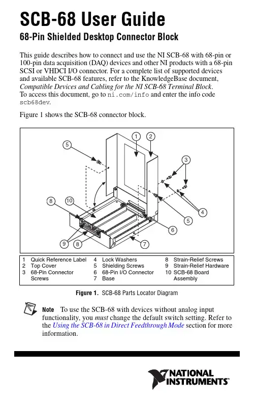
SCB-68 User Guide68-Pin Shielded Desktop Connector BlockThis guide describes how to connect and use the NI SCB-68 with 68-pin or 100-pin data acquisition (DAQ) devices and other NI products with a 68-pin SCSI or VHDCI I/O connector. For a complete list of supported devices and available SCB-68 features, refer to the KnowledgeBase document, Compatible Devices and Cabling for the NI SCB-68 Terminal Block . To access this document, go to /info and enter the info code scb68dev .Figure 1 shows the SCB-68 connector block.Figure 1. SCB-68 Parts Locator DiagramNoteTo use the SCB-68 with devices without analog inputfunctionality, you must change the default switch setting. Refer to the Using the SCB-68 in Direct Feedthrough Mode section for more information.SCB-68 User Guide2What You Need to Get StartedTo set up and use your SCB-68, you need the following:❑SCB-68 68-pin shielded connector block kit(s)1, containing the SCB-68, SCB-68 quick reference label, and SCB-68 User Guide❑Compatible 68-pin or 100-pin DAQ device, and device documentation ❑The correct cable(s) for your device, as listed in the KnowledgeBase document, Compatible Devices and Cabling for the NI SCB-68 Terminal Block . To access this document, go to /info and enter the info code scb68dev .❑Phillips #1 and #2 screwdrivers ❑0.125 in. flathead screwdriver ❑14–30 AWG wire ❑Wire cutters❑Wire insulation stripperGetting Started with the SCB-68The following cautions contain important safety information concerning hazardous voltages and connector blocks.Cautions To avoid electrical shock, do not remove equipment covers or shields unless you are qualified to do so. Before removing the cover, disconnect any live circuit from the connector block.The chassis ground terminals on your SCB-68 are for grounding high-impedance sources, such as a floating source (1mAmaximum). Do not use these terminals as safety earth grounds.Do not connect hazardous voltages (≥42 V pk /60 VDC).1 You can use up to two SCB-68 accessories with AO/M Series devices with two connectors andE Series 100-pin devices.You can use up to four SCB-68 accessories with R Series devices with four connectors, and up tothree SCB-68 accessories with R Series devices with three connectors.Figure2 shows the SCB-68 board parts locator diagram.Figure 2. SCB-68 Printed Circuit Board DiagramTo get started with the SCB-68, complete the following steps while referring to Figures1 and2. If you have not already installed your DAQ device, refer to the DAQ Getting Started Guide for instructions.1.Disconnect the cable from the SCB-68, remove the shielding screws witha Phillips #1 screwdriver, and open the top cover.2.Attach the quick reference label to the inside of the top cover as shownin Figure1. For quick reference label PDFs for most compatible devices,refer to the KnowledgeBase document, Where Can I Find© National Instruments Corporation3SCB-68 User GuideSCB-68 User Guide4SCB-68/SCB-100 Quick Reference Labels?. To access thisKnowledgeBase, go to /info and enter the info code rdwpdf .3.Configure switches for the signal types you are using, as explained in the Using the SCB-68 in Direct Feedthrough Mode section or the Using the SCB-68 with MIO DAQ Devices section.4.Adjust the strain-relief hardware by loosening the strain-relief screws with a Phillips #2 screwdriver and sliding the signal wires through the front panel strain-relief opening. If you are connecting multiple signals, remove the top strain-relief bar and add insulation or padding if necessary.5.Connect the wires to the screw terminals by stripping 6.35 mm (0.25in.) of insulation, inserting the wires into the screw terminals, and securely tightening the screws with the flathead screwdriver to a torque of 0.5–0.6N ⋅ m (4.43–5.31 lb ⋅ in.).6.Reinstall the strain-relief (if removed) and tighten the strain-relief screws.7.Close the top cover and reinsert the shielding screws to ensure proper shielding.CautionDo not connect input voltages ≥42.4V pk /60VDC tothe SCB-68. The SCB-68 is not designed for any input voltages ≥42.4V pk /60 VDC, even if a user-installed voltage divider reduces the voltage to within the input range of the DAQ device. Input voltages ≥42.4V pk /60 VDC can damage the SCB-68, all devices connected to it, and the host computer.8.Connect the SCB-68(s) to the DAQ device using the appropriate cable(s)for your device. For a complete list of cabling options for supported devices, refer to the KnowledgeBase document, Compatible Devices and Cabling for the NI SCB-68 Terminal Block . To access this document, go to /info and enter the info code scb68dev .unch Measurement & Automation Explorer (MAX), confirm that yourDAQ device is recognized, and configure your device settings. Refer to the DAQ Getting Started Guide for more information.10.(Optional) If you are going to take measurements with an MIO DAQdevice, configure the SCB-68 as an accessory for a DAQ device using MAX by completing the following steps.a.Navigate to MAX by selecting Start»Programs»NationalInstruments»Measurement & Automation .b.In the left pane of MAX, expand Devices and Interfaces , thenright-click on your DAQ device and select Properties from the pull-down menu.c.Select the Accessory tab from the dialog box, select SCB-68 fromthe pull-down menu, then select Configure.For more information about configuring the SCB-68 for a DAQ device, refer to the Measurement & Automation Explorer Help for NI-DAQmx.11.Test specific device functionality. Refer to the DAQ Getting StartedGuide for detailed information about running test panels in MAX. When you have finished using the SCB-68, power off any external signals connected to the SCB-68 before you power off your computer.Using the SCB-68 in Direct Feedthrough ModeHigh-Speed Digital I/O (DIO), NI Switch, R Series, AO Series, andTIO Series devices, and devices without analog input functionality must use direct feedthrough mode. Move the switches to the direct feedthrough mode switch setting shown in Table1.Table 1. Direct Feedthrough Switch SettingFigure 3. Direct Feedthrough Mode Switch Setting© National Instruments Corporation5SCB-68 User GuideUsing the SCB-68 with MIO DAQ DevicesYou can take measurements with the SCB-68 and multifunction I/O (MIO) DAQ devices, such as E/M/S Series devices, in a number of ways. Switches S1 and S2 provide power to the signal conditioning area of the accessory. The SCB-68 has a temperature sensor for cold-junction compensation (CJC) to accommodate thermocouples; switches S3, S4, and S5 configure the temperature sensor for different analog input settings. Table2 shows the different switch settings for MIO DAQ devices.Table 2. MIO DAQ Device Switch SettingsSCB-68 User Table 2. MIO DAQ Device Switch Settings (Continued)Figure 4. MIO DAQ Device Modes Switch Settings© National Instruments Corporation7SCB-68 User GuideConnecting Signal Sources to Analog InputsFor detailed information about connections from floating orground-referenced signal sources to analog inputs, refer to your device documentation.Refer to the SCB-68 User Manual for Advanced Functions for more information about using the temperature sensor, taking thermocouple measurements, and adding bias resistors and signal conditioning components to the SCB-68.Fuse and Power InformationSome DAQ devices provide +5 V power on pin 8 and pin 14. Pin 8 from the DAQ device is protected by an 800 mA, 250 V, 5 · 20 mm fuse on the SCB-68, shown in Figure2. Shorting pin 8 to ground blows the fuse on the SCB-68. Pin 14 is not fuse-protected on the SCB-68. Shorting pin 14 will cause the fuse on the DAQ device to open.If the SCB-68 does not work when you power on the DAQ device, check the switch settings, then check the fuse on the SCB-68, shown in Figure2, and the output fuse (if any) on the DAQ device. Littelfuse part number 235.800 () is a suitable replacement fuse. Before replacing any fuses, check for short circuits from power to ground.Refer to the SCB-68 User Manual for Advanced Functions for information about filtering the power on the SCB-68.Where to Go from HereRefer to the SCB-68 User Manual for Advanced Functions, available from /manuals, for information about the temperature sensor, thermocouple measurements, bias resistors, soldering components on the SCB-68, filtering, current input measurements, and accessory specifications. National Instruments, NI, , and LabVIEW are trademarks of National Instruments Corporation. Refer to the Terms of Use section on /legal for more information about National Instruments trademarks. Other product and company names mentioned herein are trademarks or trade names of their respective companies. For patents covering National Instruments products/technology, refer to the appropriate location: Help»Patents in your software, the patents.txt file on your media, or the National InstrumentsPatent Notice at /patents.© 1994–2009 National Instruments Corp. All rights reserved.371745C-01Mar09。
ZN65-12户内高压真空断路器一. 概述断路器作为配电线路中的一个重要元件,承担着线路电力的接通、切断、故障保护等功能。
真空断路器以其绝缘强度高,熄弧能力强,没有火灾和爆炸危险等诸多优点而受到电力部门的完全认可,在7.2kV ~12kV 范围内,真空断路器以占绝对优势,并在很短的时间内会完全取代油(或少油)断路器。
九十年代以来,国外著名的公司纷纷推出新一代12kV 真空断路器,如德国SIEMENS 公司推出的3AH1~3AH5系列真空断路器,ABB 公司推出的VD4型真空断路器,日本三菱公司推出的VK 型真空断路器等等。
它们显著的特点是:可靠性大为提高,尺寸小巧,外观精美,适合目前电力行业的发展要求。
随着我国电力事业的大力发展,市场迫切需要在性能、可靠性、外观上接近但价格明显低于国外同类产品的真空断路器。
根据这一趋势,我厂根据我国电力行业的要求和国际上真空断路器技术发展的最新发展趋势自行研制开发的ZN65A-12型新一代系列户内交流真空断路器,并通过甘肃省经济贸易委员会组织的专家鉴定。
本断路器可以使用在交流50Hz (60Hz ),12kV 及以下的电力系统中。
ZN65A –12系列户内高压真空断路器符合GB1984、DL403、GB/T11022、IEC56等标准规定,并在国家高压电器质量监督检验中心和KEMA 试验站通过了严格的型式试验。
二. ZN65A-12/T630~4000-20~63系列交流高压真空断路器技术参数(表1)表1(2括号内参数为配SIEMENS 公司, 无锡SIEMENS 公司, 美国西屋公司真空灭弧室参数。
1. 断路器装配调整后,其机械特性参数应符合表2数据表22. 储能电机(采用单相串激电动机),其技术数据见表3。
表33. 分合闸线圈技术数据见表4 表4图一1 机构箱体2 绝缘子3 灭弧室4 上出线端5 安装挂板6 合闸弹簧7 辅助开关8 二次插头9 分闸电磁铁 10 合闸电磁铁 11油缓冲 12软连接 13 下出线端 14 变直传动机构 15绝缘推杆 16 分闸弹簧三. 使用环境要求a. 周围空气温度上限不高于+40 ︒C 、下限不低于-10︒C ;b. 海拔不超过1000m 。
编号:XGN2-12高压开关柜使用说明书襄阳展宇电气有限公司XIANGFAN ZHANYU ELECTRIC CO.,LTD.公司地址:湖北省襄阳市春园西路101号技术服务:传真:(0710)3342898销售直拨:(0710)3343998 邮编:441000前言感谢您选用展宇电气XGN2-12型高压开关柜系列产品。
本说明书提供给用户安装、运行参数设定、异常诊断、日常维护及安全使用相关注意事项。
为了保证正确地安装及操作本产品,请在装机之前,详细阅读本使用说明书。
我们的服务就和我们的产品一样,全体员工一直坚信用户是上帝的原则。
如在使用过程中遇到解决不了的疑难问题,请联络本公司的各地经销商或直接与本公司联系。
产品购入后,请检查本产品是否因运输不慎而造成损伤;产品的规格、型号是否与订购产品的机种相符;有无合格标志等。
由于产品在不断地更新换代可能出现设备及产品的个别地方或文字与宣传资料不符,如果发现设备出现此种问题请咨询本公司。
拆箱后请检查设备前柜门内文件盒内的产品说明书。
如有问题,请与供货商联系。
希望用户妥善保管本说明书,这对今后的维护、保养以及其它应用的场合会有所俾益。
用户应将本说明书交给直接使用或操作人员手中,如需对本说明书存档,请与本公司联系,本公司将免费为您提供一套存档用说明书。
安全警告✧禁止野蛮搬运及安装,禁止雨淋,远离电磁干扰。
✧防止儿童和公众接触或接近本设备,本设备有危险电压。
✧本设备只能按照制造商规定的用途使用,未经授权的修改或不按本手册的规定操作可能会导致严重地人身伤害及其它伤害。
✧只有经过严格训练的专业操作人员及专业技术人员才能允许操作及维护本产品。
✧请在操作本设备前,认真阅读本手册中的所有安全说明安装操作和维护规程。
目录1、概述 (4)2、产品型号及含义 (4)3、主要技术数据 (4)4、结构概述 (6)5、使用说明 (7)6、安装 (7)7、维护要点 (8)8、包装、运输、存储和启封 (9)9、订货须知 (9)一、概述◆主要用途XGN2-12型高压开关柜,适用于3~10kV三相50HZ交流单母线系统,作为接受和分配电能用。


医学体外诊断试剂---产品临床意义1.D-二聚体测定试剂盒(D-Dimer)2.纤维蛋白(原)降解产物测定试剂盒(FDP)13.抗凝血酶III测定试剂盒(AT-III)4.纤维蛋白溶酶原测定试剂盒(S-PLG)5.凝血酶原时间测定试剂盒(PT)6.活化部分凝血活酶时间测定试剂盒(APTT)37.凝血酶时间测定试剂盒(TT)8.纤维蛋白原测定试剂盒(FIB)9.a2纤溶酶抑制物测定试剂盒(S-APL)10.铜兰蛋白(CP)11.总胆汁酸(TBA )12.前白蛋白(PA)13.腺苷脱氨酶(ADA )14.5 ‘ -核苷酸酶(5 ‘-NT)15.胆碱酯酶(CHE )16.a-L岩藻糖苷酶(AFU)17.甘胆酸(CG )18.亮氨酸氨基肽酶(LAP)19.总胆红素(TBIL)20.直接胆红素(DBIL)21.丙氨酸氨基转移酶(ALT)22.天门冬氨酸氨基转移酶(AST)23.天冬氨酸氨基转移酶线粒体同工酶(ASTm )124.碱性磷酸酶(ALP)25.Y -谷氨酰氨基转移酶(GGT )26.总蛋白(TP)27.白蛋白(ALB)28.胱抑素 C (Cysc)29.视黄醇结合蛋白(RBP )30.0 2微球蛋白(0 2MG )31.a1微球蛋白测定试剂盒(a1-MG )32.N-乙酰-0-D-M基葡萄糖苷酶(NAG )33.肌酐(CR )34.尿酸(UA)35.尿素氮(BUN )36.尿总蛋白(UTP )37.尿微量白蛋白(MALB)38.纤维蛋白(原)降解产物(FDP )39.同型半胱氨酸(HCY)40.游离脂肪酸(NEFA)41.血管紧张素转化酶(ACE )42.超敏C反应蛋白(HS-CRP)43.甘油三酯(TG )44.总胆固醇(TCH)45.高密度脂蛋白胆固醇(HDL-C)46.低密度脂蛋白胆固醇(LDL-C)47.载脂蛋白 AI(ApoAI)48.载脂蛋白B(ApoB)49.载脂蛋白E( ApoE)50.脂蛋白(a)(LP(a))51.肌红蛋白(Mb)52.肌钙蛋白I(cTn I)53.肌酸激酶同工酶(CKMB )54.肌酸激酶(CK)55.乳酸脱氢酶(LDH)56.a-羟丁酸脱氢酶(HBDH )57.葡萄糖(GLU )58.糖化血清蛋白(GSP )59.糖化血红蛋白(HBAIC)60.糖化白蛋白(GA )61.0-羟丁酸(0-DH)62.乳酸(Lac)63.丙酮酸(PYR)64.a-淀粉酶(a-AMY )65.脂肪酶(LIP)66.钙离子(Ca)67.镁离子(Mg )68.无机磷(P)69.二氧化碳(Co2 )70.钾离子(K)71.钠离子(Na )72.氯离子(CI)73.锌离子(Zn)74.铁离子(Fe)75.抗链球菌溶血素O(ASO )76.类风湿因子(RF)77.C-反应蛋白(CRP)78.铁蛋白(Ferr)79.转铁蛋白(Tf)80.免疫球蛋白G (IgG)81.补体C3(C3)82.B 因子(BF)83.al-酸性糖蛋白(a 1-AG )84.al-抗胰蛋白酶(a1-AT)85.尿a2巨球蛋白(Ua2-MG )86,唾液酸(SIA)87.超氧化物歧化酶(SOD )尿液蛋白临床意义体外诊断试剂产品临床意义1.D-二聚体测定试剂盒(D-Dimer)方法学:乳胶增强免疫比浊法参考值:血浆:01.0mg/L线性范围:0.520mg/LD-二聚体是在血液凝固与纤溶系统中,由于凝固第十三因子的作用,安定的交联纤维蛋白被纤溶酶分解的FDP的一种,血液中存在YY/DXD、YD/DY、DD/E、DD复合体等各种分子类的D-二聚体。
ZN118‐12 系列纵旋隔离真空断路器一.概述ZN118-12型纵旋隔离真空断路器,是广东维能电气有限公司自主研发的新-代智能化、小型化、安全可靠、节能环保的户内高压纵旋式隔离真空断路器。
其主要特点是集真空断路器、隔离开关及智能单元于一体,主回路采用纵向布置,产品结构简单紧凑,隔离断口可视安全,断路器从工作位置到试验位置(隔离位置)及隔离开关的操作既可手动又可电动。
适用于额定电压12kV、额定频率50Hz 的户内三相交流电力系统,是工矿企业、变电所及发电厂等受、配电系统进行控制、保护、监测的配电设备。
二.型号说明三.使用环境最高环境温度:+40℃最低环境温度:-25℃最大日平均温度:+35℃日平均相对湿度:不大于95%月平均相对湿度:不大于90%最大海拔高度:不超过1000m最大地震烈度:不超过Ⅷ度污秽等级:不低于Ⅱ级应安装在无火灾、无爆炸危险、无严重污染、无化学腐蚀气体及剧烈振动的场所。
若超出上述正常条件,用户可与制造厂协商解决。
四.产品特点断路器由三相可旋转的灭弧室极柱和固定不动的双功能一体化操作机构两大部分组成,通过手车支架和横梁,将两者构成一体,形成纵向布置,机构固定不动,且极柱旋转的手车式隔离真空断路器,与KYN88柜体配合,实现推进和抽出,构成中置式手车柜。
三相导电极柱,通过上、下两端的指形动触头出线,在柜中实现上与主母线、下与电流互感器的电气联接。
三相极柱固定在金属支撑件上,金属支撑件内装有驱动连杆系统,实现断路器分、合闸操作和极柱旋转功能,与传统固定安装的断路器具有实质性的差别。
断路器与隔离操作既可手动又可电动。
1.载流效果好,散热效率高三相极柱结构紧凑,在工作位置时,上下贯通,散热对流通畅,垂直轴流式散热结构消除了带触臂式出线,插入触头盒结构内存在发热死区的缺陷。
2.创新的隔离断路器,安全可靠既具有断路器的功能又具有隔离开关的功能,隔离断口无需移动手车,可形成两个可见隔离断口,安全可靠。
苏州锜达电子有限公司常用金属材料手册铬在钢中的角色多元且重要,它会形成安定而硬的炭化物,而且具抗腐蚀性,其主要作用有:A)增进钢的硬化能和渗炭作用;B)使钢在高温时仍具高强度;C)能增加耐磨耗性;D)增高钢之淬火温度;E)能增进钢的抗腐蚀性。
2.镍Ni镍在钢中的影响有:A)增进钢的硬化能;B)能降低热处理时的淬火温度,因之在处理时变形小;C)能增加钢的韧性;D)高镍合金钢耐腐蚀性,列如:不锈钢就含有8%左右的镍。
3.钨W钨能耐高温,而且溶于钢中会与碳形成碳化物称为碳化钨,能提高钢的强度。
此外:A)可以提高钢之淬火温度;B)加强钢之断面组织细微化,抵抗回火软化;C)可以降低淬火时钢之晶粒生长之趋势;D)钨钢刀具有红热硬度;E)可增加钢之保磁性,故可配入钢中而制造永久磁钢。
4.钒V钒可以无限量固溶入铁中,并阻止铁晶粒的成长,钒在钢中有脱酸除氧之能力,故含钒之钢其断面结晶密实,此外钒的作用还有:A)可以提高钢之淬火温度;B)改善硬化能,高温淬火加热时能防止其晶粒生长;C)有助于钢之结晶组织细微化。
5.锰Mn锰在钢中的影响有:A)在适量下,锰量增加可增加钢之最大强度及硬度;B)具有脱氧及脱硫功效,故锰能发挥钢之锻造性与可塑性;C)锰在钢中含量多,可降低钢之淬火温度;D)可增进钢之硬化深度,尤其在含碳量高之硬性锰钢尤为显著。
6. 钼Mo钼可增加钢之最大强度及硬度,其影响还有:A)能改善钢在高温下之抗拉及潜变强度;B)在工作红热情况下,能使钢之硬度保持不变;C)高速工具钢含钼,可予以较佳之切割性能;D)合金钢中加入钼可去除回火脆性。
钴为制造合金钢之重要元素,在钢中可以生成碳化物,但也可能有不良影响,它具有以下特性:A)钴可代替镍,如增加强度及耐热等性能;B)会降低钢的硬化能;C)能提高钢之淬火温度;D)增加钢之保磁能力,故为制造磁石钢之主要元素。
8.钛Ti钛在钢中易与碳形成碳化物TiC,其它特性:A)钛在不锈钢中,可以防止高温时铬量的局部减少,维持其防腐蚀能力;B)可以防止合金钢由高温徐冷时的脆化现象。