DS3234翻译
- 格式:doc
- 大小:714.50 KB
- 文档页数:15
代码部分:#in elude <reg51.h> #in elude vintrin s.h>#defi ne uehar un signed char#defi ne uintun sig ned int// 模拟 I2C 数据传送位 SDA************** // 模拟 I2C 时钟控制位 SCL**************sbit INT=P3A2; sbit RESET=P3A3; 〃 ************** sbit led0=P1A0; sbit led 1=P1A1; sbit led2=P1A2; sbit led3=P1A3; sbit led4=P1A4; sbit led5=P1A5; sbit led6=P"6; sbit led7=P1A7; 〃 **************接线说明,以 Ardui no uno r3 为例:sbit SDA=P3A 6; sbit SCL=P3A7;bit ack; //应答标志位#defi ne DS3231 WriteAddress OxDO //器件写地址**************#defi ne DS3231 ReadAddress 0xD1 //器件读地址**************#defi ne DS3231 SECOND 0x00 //秒#defi ne DS3231 MINUTE 0x01 //分#defi neDS3231 HOUR 0x02 //时#defi neDS3231 WEEK 0x03 //星期#defi neDS3231 DAY 0x04 //#defi neDS3231 MONTH 0x05 //月#defi neDS3231 YEAR 0x06 //〃闹铃1#defi neDS3231 SALARM1ECOND 0x07 //秒#defi ne DS3231 ALARM1MINUTE 0x08 //分#defi ne DS3231 ALARM1HOUR 0x09 //时#defi ne DS3231 ALARM1WEEK 0x0A //星期/日〃闹铃2#define DS3231 ALARM2MINUTE 0x0b //分#defi ne DS3231 ALARM2HOUR 0x0c //时#define DS3231 ALARM2WEEK 0x0d //星期/日#defi neDS3231 CONTROL 0x0e //控制寄存器#defi neDS3231 STATUS 0x0f //状态寄存器#defi ne BSY2 〃忙#defi ne DS3231_TEMPERATUREH 0x11 #defi ne DS3231 TEMPERATUREL 0x12uchar code dis_code[11]={0xc0,0xf9,0xa4,0xb0.0x99,0x92,0x82,0xf8,0x80,0x90, 0xff};uchar data dis_buf[8]; uchar data dis_i ndex; uchar data dis_digit; // **************uchar temp; temp=val&0x0f; val>>=4; val&=0x0f; val*=10; temp+=val;#defi ne OSF7 //振荡器停止标志 #defi ne DS3231_XTAL0x10//晶体老化寄存器// **************//温度寄存器高字节(8位) //温度寄存器低字节(高2位)// 0,1,2,3 // 4,5,6,7,8,9,offuchar BCD2HEX(uchar val) //BCD 转换为Bytereturn temp;}uchar HEX2BCD(uchar val) 〃B 码转换为 BCD 码{uchar i,j,k;i=val/10;j=val-i*10 ; **************k=j+(i<<4);return k;}void delayus(ui nt us) 注:单片机型号不同{while (us--);} void Start_I2C(){SDA=1; //发送起始条件的数据信号delayus(1);SCL=1;delayus(5); //起始条件建立时间大于 4.7us,延时SDA=O; //发送起始信号delayus(5); //起始条件锁定时间大于4阴SCL=O; //钳住I2C总线,准备发送或接收数据delayus(2);} void Stop_l2C(){SDA=0; //发送结束条件的数据信号delayus(1); //发送结束条件的时钟信号SCL=1; //结束条件建立时间大于4usdelayus(5);SDA=1; //发送I2C总线结束信号delayus(4);}void Sen dByte(uchar c){uchar BitC nt;for(BitCnt=O;BitCnt<8;BitCnt++) // 要传送的数据长度为8 位{if((c<<BitC nt)&0x80)SDA=1; //判断发送位elseSDA=0;delayus(1);SCL=1; //置时钟线为高,通知被控器开始接收数据位delayus(5); //保证时钟高电平周期大于 4阴SCL=0;}delayus(2);SDA=1; //8位发送完后释放数据线,准备接收应答位delayus(2);SCL=1;delayus (3);if(SDA==1)ack=0;elseack=1; //判断是否接收到应答信号SCL=O;delayus(2);}uchar RcvByte(){uchar retc;uchar BitC nt;retc=0;SDA=1; //置数据线为输入方式for(BitC nt=O;BitC nt<8;BitC nt++){delayus(1);SCL=0; //置时钟线为低,准备接收数据位delayus(5); //时钟低电平周期大于 4.7阴SCL=1; //置时钟线为高使数据线上数据有效delayus (3);retc=retc<<1;if(SDA==1)retc=retc+1; //读数据位,接收的数据位放入retc 中delayus(2);}SCL=O;delayus(2);return(retc);}void Ack_l2C(bit a){if(a==0)SDA=0; //在此发出应答或非应答信号elseSDA=1;delayus (3);SCL=1;delayus(5); //时钟低电平周期大于 4 qSCL=O; //清时钟线,钳住I2C总线以便继续接收delayus(2);}uchar write_byte(uchar addr, uchar write_data){Start_I2C();Se ndByte(DS3231_WriteAddress);if (ack == 0)return 0;Se ndByte(addr);if (ack == 0)return 0;Sen dByte(write_data);if (ack == 0)return 0;Stop_I2C();delayus(10);return 1;}uchar read_curre nt(){uchar read_data;Start_l2C();Sen dByte(DS3231_ReadAddress); if(ack==O) return(O);read_data = RcvByte();Ack_I2C(1);Stop_I2C();return read_data;}uchar read_ra ndom(uchar ran dom_addr){Start_I2C();。

DS3231详细介绍(⾮芯⽚⼿册)年误差⼩于1分钟⾼精度时钟DS3231的设计及应⽤深圳市凌雁电⼦有限公司[1].前⾔在许多单⽚机的测控系统和家⽤电器中都含有时钟显⽰部分,最廉价的是直接使⽤单⽚机中的定时器,辅以⼀定的中断服务程序,构成时钟显⽰部分,这种⽅式是⼏乎不需要增加新的硬件即可实现,缺点是计时误差⼤,同时电源掉电不能保持时钟继续运⾏。
在相对要求较⾼的场合,则使⽤廉价的时钟芯⽚(如DS1302等等)辅以备⽤电池,计时精度略⾼,可满⾜⼀般的要求。
在这篇⽂章中,我们重点介绍⾼精度时钟电路DS3231的设计和应⽤。
在DS1302普及型时钟芯⽚,晶体均需外置,由于晶体的离散性,很难选择到精度很⾼的器件,同时也没有温度补偿电路,不同的温度环境下,晶体的特性也在变化,直接影响着时钟的振荡频率,较⼤的误差在所在所难免。
⽽DS3231⾼精度时钟芯⽚,将晶体和温度补偿均集成在芯⽚中,为提⾼计时精度提供了可能,实册证明,使⽤DS3231时钟芯⽚,误差可做到⼀年⼩于⼀分钟,甚⾄部分显⽰器误差可⼩于20秒/⼀年。
这对有相对精确时钟要求的应⽤场合是个理想的选择。
[2].DS3231时钟芯⽚结构原理DS3231是⼀款⾼精度I2C实时时钟(RTC)器件,具有集成的温度补偿晶体振荡器(TCXO)。
该器件包含电池输⼊端,断开主电源时仍可保持精确计时。
集成的晶体振荡器可提⾼器件的长期精确度。
DS3231的寄存器能保存秒、分、时、星期、⽇期、⽉、年和闹钟设置等信息。
少于31天的⽉份,可⾃动调整⽉末⽇期,包括闰年补偿。
时钟的⼯作格式为24⼩时或带AM/PM指⽰的12⼩时格式。
DS3231提供两个可编程⽇历闹钟和⼀路可编程⽅波输出。
DS3231与单⽚机通过I2C双向串⾏总线传输地址与数据。
下图为DS3231典型应⽤电路,图中可看出,DS3231⼏乎不需要外部元件。
[3].DS3231时钟芯⽚结构如图1所⽰,DS3231的主要组成部分有8个模块,划分为4个功能组:TCXO、电源控制、按钮复位和RTC。
1/8DATA BRIEFINGJune 2002Complete data available on Data-on-Disc CD-ROM or at .µPSD3200FAMILYFlash Programmable System Devicewith 8032Microcontroller CoreFEATURES SUMMARYs The µPSD3200Family combines a Flash PSD architecture with an 8032microcontroller core The µPSD3200Family of Flash PSDs features dual banks of Flash memory,SRAM,general purpose I/O and programmable logic,supervi-sory functions and access via USB,I 2C,ADC,DDC and PWM channels,and an on-board 8032microcontroller core,with two UARTs,three 16-bit Timer/Counters and one External Interrupt.As with other Flash PSD families,the µPSD3200Family is also in-system program-mable (ISP)via a JTAG ISP interface.sLarge 8KByte SRAM with battery back-up optionsDual bank Flash memories–128KByte or 256KByte main Flash memory –32KByte secondary Flash memorysContent Security–Block access to Flash memorysProgrammable Decode PLD for flexible address mapping of all memories.s High-speed clock standard 8032core (12-cycle)s USB Interface (µPSD3234A-40U6only)s I 2C interface for peripheral connections s Five Pulse Width Modulator (PWM)channels s Standalone Display Data Channel (DDC)s Six I/O ports with up to 50I/O pins s 3000gate PLD with 16macrocells s Supervisor functionss In-System Programming (ISP)via JTAG s Zero-Power Technology sSingle Supply Voltage –4.5to 5.5V –3.0to 3.6VFigure 1.PackagesTQFP52(T)TQFP80(U)µPSD3200FAMILY2/8SUMMARY DESCRIPTION s Dual bank Flash memories–Concurrent operation,read from memory one while erasing and writing the other.In-Appli-cation Programming (IAP)for remote updates –Large 128KByte or 256KByte main Flash memory for application code,operating sys-tems,or bit maps for graphic user interfaces –Large 32KByte secondary Flash memory di-vided in small sectors.Eliminate external EE-PROM with software EEPROM emulation –Secondary Flash memory is large enough for sophisticated communication protocol (USB)during IAP while continuing critical system taskssLarge SRAM with battery back-up option –8KByte SRAM for RTOS,high-level languag-es,communication buffers,and stackssProgrammable Decode PLD for flexible address mapping of all memories–Place individual Flash and SRAM sectors on any address boundary –Built-in page register breaks restrictive 8032limit of 64KByte address space –Special register swaps Flash memory seg-ments between 8032“program”space and “data”space for efficient In-Application Pro-grammingsHigh-speed clock standard 8032core (12-cycle)–40MHz operation at 5V,24MHz at 3.3V –Two UARTs with independent baud rate,three 16-bit Timer/Counters and two External InterruptssUSB Interface (µPSD3234A-40U6only)–Supports USB 1.1Slow Mode (1.5Mbit/s)–Control endpoint 0and interrupt endpoints 1and 2sI 2C interface for peripheral connections –Capable of master or slave operation sFive Pulse Width Modulator (PWM)channels –Four 8-bit PWM units–One 16-bit PWM unitsStandalone Display Data Channel (DDC)–For use in monitor,projector,and TV applica-tions –Compliant with VESA standards DDC1and DDC2B –Eliminate external DDC PROM s Six I/O ports with up to 50I/O pins–Multifunction I/O:GPIO,DDC,I 2C,PWM,PLD I/O,supervisor,and JTAG –Eliminates need for external latches and logics3000gate PLD with 16macrocells–Create glue logic,state machines,delays,etc.–Eliminate external PALs,PLDs,and 74HCxx –Simple PSDsoft Express software ...FreesSupervisor functions–Generates reset upon low voltage or watch-dog time-out.Eliminate external supervisor device –Reset In pinsIn-System Programming (ISP)via JTAG –Program entire chip in 10-25seconds with no involvement of 8032–Allows efficient manufacturing,easy product testing,and Just-In-Time inventory –Eliminate sockets and pre-programmed parts –Program with FlashLINK TM cable and any PCsContent Security–Programmable Security Bit blocks access of device programmers and readerssZero-Power Technology–Memories and PLD automatically reach standby current between input changessPackages –52-pin TQFP–80-pin TQFP:allows access to 8032address/data/control signals for connecting to external peripherals3/8µPSD3200FAMILYFigure 2.µPSD3200Family Functional ModulesAI066194Channel ADC1Mb or 2Mb Main FlashDecode PLD64Kb SRAMCPLD -16MACROCELLSJTAG ISP Port 1Port 32UARTS Interrupt3Timer /Counters256Byte SRAM8051Core Port 3,UART,Intr,Timers,I2CPSD Internal Bus8032Internal BusUSB &TransceiverPort 1,Timers and 2nd UART and ADCDDC w/256Byte SRAM PWM 5Channels Port 4PWM and DDCDedicated USB PinsPort A &B,PLD I/O and GPIOPort D GPIO Port C,JTAG,PLD I/O and GPIOVCC,GND,XTAL256Kb Secondary FlashDedicated PinsI2CPort 0,2Ext.BusReset LogicLVD &WDTBus InterfaceResetD0-D7A0-A15RD,PSEN WR,ALEPage Register PSD MODULEMCU MODULEµPSD3200FAMILY4/8Table 1.80-Pin Package Pin DescriptionNote:PSD Port A and MCU Address/Data bus are added for 80-pin deviceSignal Name In/Out FunctionBasicAlternateAD7-AD0I/O Multiplexed Address/Data bus A11-A8I/O External Address BusRxD2-RxD1I/O General I/O port pinsUART Receive TxD2-TxD1I/O UART TransmitINT1-INT0I/O Interrupt inputs /timer gate controls T2-T0I/O Counter inputsSDA1-SDA2I/OI 2C Bus serial data I/O /DDC interface SCL1-SCL2I/O I 2C Bus clock I/OVSYNC I/O VSYNC input for DDC interface T2EX I/O Timer 2Trigger input ADC3-ADC0I/O ADC Channels inputPWM4-PWM0I/O 8-bit Pulse Width Modulation outputsUSB-,USB+I/O USB I/OAVREF O Reference Voltage input for ADC RD_O Read signal,external bus WR_O Write signal,external bus PSEN_O PSEN signal,external bus ALE O Address Latch signal,external bus RESET_I Active low reset inputXTAL1I Oscillator input pin for system clock XTAL2OOscillator output pin for system clockPA7-P A0I/O General I/O port pins1.PLD Macro-cell outputs2.PLD inputstched Address Out (A0-A7)4.Peripheral I/O mode PB7-PB0I/O General I/O port pins1.PLD Macro-cell outputs2.PLD inputstched Address Out (A0-A7)PC7-PC0I/O General I/O port pins1.PLD Macro-cell outputs2.PLD inputs3.SRAM stand by voltage input (VSTBY)4.JTAG Interface (TDI,TDO,TMS,TCK,TSTA T,TERR)5.SRAM battery-on indicator (PC4)PD2-PD1I/O General I/O port pin1.PLD I/O2.Clock input to PLD and APD3.Chip select to PSD ModuleµPSD3200FAMILY Figure3.TQFP52ConnectionsNote:NC=Not ConnectedPU=Pull-up resistor required(2kΩfor3V devices,7.5kΩfor5V devices)39P1.5/ADC1 38P1.4/ADC0 37P1.3/TXD1 36P1.2/RXD1 35P1.1/T2X 34P1.0/T233V CC32XTAL231XTAL130P3.7/SCL1 29P3.6/SDA1 28P3.5/T127P3.4/T0PD1 PC7 PC6 PC5 PU PC4 NC V CC GND PC3 PC2 PC1 PC0 12345678910111213525154948474645444342414PBPB1PB2PB3PB4PB5VREFGNDRST-INPB6PB7ADC3ADC21415161718192212223242526P4.7/PWM4P4.6/PWM3P4.5/PWM2P4.4/PWM1P4.3/PWMGNDP4.2/DDCVSYNCP4.1/DDCSCLP4./DDCSDAP3./RXDP3.1/TXDP3.2/EXINTP3.3/EXINT1AI05790B5/8µPSD3200FAMILY6/8Figure 4.TQFP80ConnectionsNote: 1.NC =Not ConnectedB-needs a pull-up resistor (see the description of the USB function)60P1.5/ADC1 59P1.4/ADC0 58P1.3/TXD1 57P2.3,A11 56P1.2/RXD1 55P2.2,A10 54P1.1/T2X 53P2.1,A9 52P1.0/T2 51P2.0,A8 50V CC 49XTAL2 48XTAL1 47P0.7,AD7 46P3.7/SCL1 45P0.6,AD6 44P3.6/SDA1 43P0.5,AD5 42P3.5/T1 41P0.4,AD4PD2 P3.3/EXINT1 PD1 PD0,ALE PC7 PC6 PC5 USB- PC4 USB+ NC V CC GND PC3 PC2 PC1 NC P4.7/PWM4 P4.6/PWM3 PC0123 45 6 7 8 9 10 11 12 13 14 15 16 1718 192080 79 78 77 76 75 74 73 72 71 70 69 68 67 66 65 64 63 62 61P B 0P 3.2/E X I N T 0P B 1P 3.1/T X DP B 2P 3.0/R X DP B 3P B 4P B 5N CV R E FG N DR E S E T -I NP B 6P B 7R D ,C N T L 1P 1.7/A D C 3P S E N ,C N T L 2W R ,C N T L 0P 1.6/A D C 22122232425262728293031323334353637383940P A 7 P A 6 P 4.5/P W M 2 P A 5 P 4.4/P W M 1 P A 4 P 4.3/P W M 0 P A 3 G N D P 4.2/D C C V S Y N C P 4.1/D D C S C L P A 2 P 4.0/D D C S D A P A 1 P A 0 A D 0,P 0.0 A D 1,P 0.1 A D 2,P 0.2 A D 3,P 0.3 P 3.4/T 0AI05791µPSD3200FAMILY PART NUMBERINGTable2.Ordering Information SchemeFor a list of available options(speed,package, etc.)or for further information on any aspect of this device,please contact your nearest ST Sales Of-fice.Example:uPSD3234B V–24U6TDevice TypeuPSD=Microcontroller PSDFamily3=8032corePLD Size2=16Macrocells3=32MacrocellsSRAM Size1=16Kbit3=64Kbit5=256KbitMain Flash Memory Size3=1Mbit4=2Mbit5=4MbitIP MixA=USB,I2C,PWM,DDC,ADC,(2)UARTsSupervisor(Reset Out,Reset In,LVD,WD)B=I2C,PWM,DDC,ADC,(2)UARTsSupervisor(Reset Out,Reset In,LVD,WD)Operating Voltageblank=V CC=4.5to5.5VV=V CC=3.0to3.6VSpeed24=24MHz40=40MHzPackageT=52-pin TQFPU=80-pin TQFPTemperature Range1=0to70°C(commercial)6=–40to85°C(industrial)OptionT=Tape&Reel Packing7/8µPSD3200FAMILYInformation furnished is believed to be accurate and reliable.However,STMicroelectronics assumes no responsibility for the consequences of use of such information nor for any infringement of patents or other rights of third parties which may result from its use.No license is granted by implication or otherwise under any patent or patent rights of STMicroelectronics.Specifications mentioned in this publication are subject to change without notice.This publication supersedes and replaces all information previously supplied.STMicroelectronics products are not authorized for use as critical components in life support devices or systems without express written approval of STMicroelectronics.The ST logo is registered trademark of STMicroelectronicsAll other names are the property of their respective owners©2002STMicroelectronics-All Rights ReservedSTMicroelectronics group of companiesAustralia-Brazil-Canada-China-Finland-France-Germany-Hong Kong-India-Israel-Italy-Japan-Malaysia-Malta-Morocco-Singapore-Spain-Sweden-Switzerland-United Kingdom-United States.8/8。

常用颜色的网络编码及中英文名称颜色网络编码英文中文#FFB6C1 LightPink 浅粉红#FFC0CB Pink 粉红#DC143C Crimson 深红/猩红#FFF0F5 LavenderBlush 淡紫红#DB7093 PaleVioletRed 弱紫罗兰红#FF69B4 HotPink 热情的粉红#FF1493 DeepPink 深粉红#C71585 MediumVioletRed 中紫罗兰红#DA70D6 Orchid 暗紫色/兰花紫#D8BFD8 Thistle 蓟色#DDA0DD Plum 洋李色/李子紫#EE82EE Violet 紫罗兰#FF00FF Magenta 洋红/玫瑰红#FF00FF Fuchsia 紫红/灯笼海棠#8B008B DarkMagenta 深洋红#800080 Purple 紫色#BA55D3 MediumOrchid 中兰花紫#9400D3 DarkViolet 暗紫罗兰#9932CC DarkOrchid 暗兰花紫#4B0082 Indigo 靛青/紫兰色#8A2BE2 BlueViolet 蓝紫罗兰#9370DB MediumPurple 中紫色#7B68EE MediumSlateBlue 中暗蓝色/中板岩蓝#6A5ACD SlateBlue 石蓝色/板岩蓝#483D8B DarkSlateBlue 暗灰蓝色/暗板岩蓝#E6E6FA Lavender 淡紫色/熏衣草淡紫#F8F8FF GhostWhite 幽灵白#0000FF Blue 纯蓝#0000CD MediumBlue 中蓝色#191970 MidnightBlue 午夜蓝#00008B DarkBlue 暗蓝色#000080 Navy 海军蓝#4169E1 RoyalBlue 皇家蓝/宝蓝#6495ED CornflowerBlue 矢车菊蓝#B0C4DE LightSteelBlue 亮钢蓝#778899 LightSlateGray 亮蓝灰/亮石板灰#708090 SlateGray 灰石色/石板灰#1E90FF DodgerBlue 闪兰色/道奇蓝#F0F8FF AliceBlue 爱丽丝蓝#4682B4 SteelBlue 钢蓝/铁青#87CEFA LightSkyBlue 亮天蓝色#87CEEB SkyBlue 天蓝色#00BFFF DeepSkyBlue 深天蓝#ADD8E6 LightBlue 亮蓝#B0E0E6 PowderBlue 粉蓝色/火药青#5F9EA0 CadetBlue 军兰色/军服蓝#F0FFFF Azure 蔚蓝色#E0FFFF LightCyan 淡青色#AFEEEE PaleTurquoise 弱绿宝石#00FFFF Cyan 青色#00FFFF Aqua 浅绿色/水色#00CED1 DarkTurquoise 暗绿宝石#2F4F4F DarkSlateGray 暗瓦灰色/暗石板灰#008B8B DarkCyan 暗青色#008080 Teal 水鸭色#48D1CC MediumTurquoise 中绿宝石#20B2AA LightSeaGreen 浅海洋绿#40E0D0 Turquoise 绿宝石#7FFFD4 Aquamarine 宝石碧绿#66CDAA MediumAquamarine 中宝石碧绿#00FA9A MediumSpringGreen 中春绿色#F5FFFA MintCream 薄荷奶油#00FF7F SpringGreen 春绿色#3CB371 MediumSeaGreen 中海洋绿#2E8B57 SeaGreen 海洋绿#F0FFF0 Honeydew 蜜色/蜜瓜色#90EE90 LightGreen 淡绿色#98FB98 PaleGreen 弱绿色#8FBC8F DarkSeaGreen 暗海洋绿#32CD32 LimeGreen 闪光深绿#00FF00 Lime 闪光绿#228B22 ForestGreen 森林绿#008000 Green 纯绿#006400 DarkGreen 暗绿色#7FFF00 Chartreuse 黄绿色/查特酒绿#7CFC00 LawnGreen 草绿色/草坪绿#ADFF2F GreenYellow 绿黄色#556B2F DarkOliveGreen 暗橄榄绿#9ACD32 YellowGreen 黄绿色#6B8E23 OliveDrab 橄榄褐色#F5F5DC Beige 米色/灰棕色#FAFAD2 LightGoldenrodYellow 亮菊黄#FFFFF0 Ivory 象牙色#FFFFE0 LightYellow 浅黄色#FFFF00 Yellow 纯黄#808000 Olive 橄榄#BDB76B DarkKhaki 暗黄褐色/深卡叽布#FFFACD LemonChiffon 柠檬绸#EEE8AA PaleGoldenrod 灰菊黄/苍麒麟色#F0E68C Khaki 黄褐色/卡叽布#FFD700 Gold 金色#FFF8DC Cornsilk 玉米丝色#DAA520 Goldenrod 金菊黄#B8860B DarkGoldenrod 暗金菊黄#FFFAF0 FloralWhite 花的白色#FDF5E6 OldLace 老花色/旧蕾丝#F5DEB3 Wheat 浅黄色/小麦色#FFE4B5 Moccasin 鹿皮色/鹿皮靴#FFA500 Orange 橙色#FFEFD5 PapayaWhip 番木色/番木瓜#FFEBCD BlanchedAlmond 白杏色#FFDEAD NavajoWhite 纳瓦白/土著白#FAEBD7 AntiqueWhite 古董白#D2B48C Tan 茶色#DEB887 BurlyWood 硬木色#FFE4C4 Bisque 陶坯黄#FF8C00 DarkOrange 深橙色#FAF0E6 Linen 亚麻布#CD853F Peru 秘鲁色#FFDAB9 PeachPuff 桃肉色#F4A460 SandyBrown 沙棕色#D2691E Chocolate 巧克力色#8B4513 SaddleBrown 重褐色/马鞍棕色#FFF5EE Seashell 海贝壳#A0522D Sienna 黄土赭色#FFA07A LightSalmon 浅鲑鱼肉色#FF7F50 Coral 珊瑚#FF4500 OrangeRed 橙红色#E9967A DarkSalmon 深鲜肉/鲑鱼色#FF6347 Tomato 番茄红#FFE4E1 MistyRose 浅玫瑰色/薄雾玫瑰#FA8072 Salmon 鲜肉/鲑鱼色#FFFAFA Snow 雪白色#F08080 LightCoral 淡珊瑚色#BC8F8F RosyBrown 玫瑰棕色#CD5C5C IndianRed 印度红#FF0000 Red 纯红#A52A2A Brown 棕色#B22222 FireBrick 火砖色/耐火砖#8B0000 DarkRed 深红色#800000 Maroon 栗色#FFFFFF White 纯白#F5F5F5 WhiteSmoke 白烟#DCDCDC Gainsboro 淡灰色#D3D3D3 LightGrey 浅灰色#C0C0C0 Silver 银灰色#A9A9A9 DarkGray 深灰色#808080 Gray 灰色#696969 DimGray 暗淡灰#000000 Black 纯黑RAL色卡电子版色号发布人:TILO天友利已被浏览 4331 次RAL 1000 Green beige RAL 1001 BeigeRAL 1002 Sand yellow RAL 1003 Signal yellowRAL 1004 Golden yellow RAL 1005 Honey yellowRAL 1006 Maize yellow RAL 1007 Daffodil yellowRAL 1011 Brown beige RAL 1012 Lemon yellowRAL 1013 Oyster white RAL 1014 Dark IvoryRAL 1015 Light Ivory RAL 1016 Sulfur yellowRAL 1017 Saffron yellow RAL 1018 Zinc yellowRAL 1019 Grey beige RAL 1020 Olive yellowRAL 1021 Rape yellow RAL 1023 Traffic yellowRAL 1024 Ochre yellow RAL 1027 CurryRAL 1028 Melon yellow RAL 1032 Broom yellowRAL 1033 Dahlia yellow RAL 1034 Pastel yellow RAL 2000 Yellow orange RAL 2001 Red orange RAL 2002 Vermilion RAL 2003 Pastel orangeRAL 2004 Pure orange RAL 2008 Bright redorangeRAL 2009 Traffic orange RAL 2010 Signal orange RAL 2011 Deep orange RAL 2012 Salmon orange RAL 3000 Flame red RAL 3001 Signal red RAL 3002 Carmine red RAL 3003 Ruby red RAL 3004 Purple red RAL 3005 Wine red RAL 3007 Black red RAL 3009 Oxide red RAL 3011 Brown red RAL 3012 Beige red RAL 3013 Tomato red RAL 3014 Antique pink RAL 3015 Light pink RAL 3016 Coral red RAL 3017 Rose RAL 3018 Strawberry red RAL 3020 Traffic red RAL 3022 Salmon pink RAL 3027 Rasberry red RAL 3031 Orient red RAL 4001 Red lilac RAL 4002 Red violet RAL 4003 Heather violet RAL 4004 Claret violet RAL 4005 Blue lilac RAL 4006 Traffic purple RAL 4007 Purple violet RAL 4008 Signal violet RAL 4009 Pastel violet RAL 4010 Tele magenta RAL 5000 Violet blue RAL 5001 Green blue RAL 5002 Ultramarine RAL 5003 Sapphire blue RAL 5004 Black blue RAL 5005 Signal blue RAL 5007 Brilliant blue RAL 5008 Grey blueRAL 5009 Azure blue RAL 5010 Gentian blue RAL 5011 Steel blue RAL 5012 Light blue RAL 5013 Cobalt blue RAL 5014 Pigeon blue RAL 5015 Sky blue RAL 5017 Traffic blue RAL 5018 Turqoise blue RAL 5019 Capri blue RAL 5020 Ocean blue RAL 5021 Water blue RAL 5022 Night blue RAL 5023 Distant blue RAL 5024 Pastel blue RAL 6000 Patina green RAL 6001 Emerald green RAL 6002 Leaf green RAL 6003 Olive green RAL 6004 Blue green RAL 6005 Moss green RAL 6006 Grey olive RAL 6007 Bottle green RAL 6008 Brown green RAL 6009 Fir green RAL 6010 Grass green RAL 6011 Reseda green RAL 6012 Black green RAL 6013 Reed green RAL 6014 Yellow oliveRAL 6015 Black olive RAL 6016 TurquoisegreenRAL 6017 May green RAL 6018 Yellow greenRAL 6019 Pastel green RAL 6020 Chrome green RAL 6021 Pale green RAL 6022 Olive drab RAL 6024 Traffic green RAL 6025 Fern green RAL 6026 Opal green RAL 6027 Light green RAL 6028 Pine green RAL 6029 Mint green RAL 6032 Signal green RAL 6033 Mint turquoiseRAL 6034 PastelturquoiseRAL 7000 Squirrel grey RAL 7001 Silver grey RAL 7002 Olive greyRAL 7003 Moss grey RAL 7004 Signal grey RAL 7005 Mouse grey RAL 7006 Beige grey RAL 7008 Khaki grey RAL 7009 Green grey RAL 7010 Tarpaulin grey RAL 7011 Iron grey RAL 7012 Basalt grey RAL 7013 Brown grey RAL 7015 Slate grey RAL 7016 Anthracite grey RAL 7021 Black grey RAL 7022 Umber grey RAL 7023 Concrete grey RAL 7024 Graphite grey RAL 7026 Granite grey RAL 7030 Stone grey RAL 7031 Blue grey RAL 7032 Pebble grey RAL 7033 Cement grey RAL 7034 Yellow grey RAL 7035 Light grey RAL 7036 Platinum grey RAL 7037 Dusty grey RAL 7038 Agate grey RAL 7039 Quartz grey RAL 7040 Window grey RAL 7042 Traffic grey A RAL 7043 Traffic grey B RAL 7044 Silk grey RAL 7045 Tele grey 1 RAL 7046 Tele grey 2 RAL 7047 Tele grey 4 RAL 8000 Green brown RAL 8001 Ocher brown RAL 8002 Signal brown RAL 8003 Clay brown RAL 8004 Copper brown RAL 8007 Fawn brown RAL 8008 Olive brown RAL 8011 Nut brown RAL 8012 Red brown RAL 8014 Sepia brown RAL 8015 Chestnut RAL 8016 Mahogany RAL 8017 Chocolate RAL 8019 Grey brown RAL 8022 Black brown RAL 8023 Orange brownRAL 8024 Beige brown RAL 8025 Pale brown RAL 8028 Terra brown RAL 9001 Cream RAL 9002 Grey white RAL 9003 Signal white RAL 9004 Signal black RAL 9005 Jet black RAL 9010 Pure white RAL 9011 Graphite black RAL 9016 Traffic white RAL 9017 Traffic blackRAL 9018 Papyrus white RAL 9006 White aluminiumRAL 9007 Grey aluminium9006 and 9007 areMetallic colours中文颜色名称颜色对照表发布人:TILO天友利已被浏览 1676 次中文颜色名称颜色对照表肌色#fedcbd桜色#feeeed白緑#cde6c7卵色#ffce7b白#fffffb胡粉色#fffef9生成色#f6f5ec灰白#d9d6c3石竹色#d1c7b7象牙色#f2eada乳白色#d3d7d4。
IBM System Storage DS3500 易捷版要点∙ 6 Gbps SAS 系统以入门级价格提供中端性能和可扩展性∙以直观而又功能强大的存储管理软件提供内置式管理专业知识∙通过经由光纤通道的远程镜像以及与DS5000 和DS4000 的兼容性提供投资保护和经济高效的备份与恢复∙以全磁盘加密提供稳健的数据安全性,并支持高性能固态驱动器∙符合NEBS 和ETSI 规范并支持48 V DC 电源IBM 在IBM® System Storage® DS3500 易捷版® 中将一流的开发与领先的 6 Gbps 主机接口和驱动器技术相结合。
凭借其简单、高效而又灵活的存储方法,DS3500 成为了IBM System x® 服务器、IBM BladeCenter® 和 IBM Power Systems™经济高效的全面集成补充。
DS3500 以适合大多数预算的价格带来了大量改进,因而为入门级存储用户提供了卓越的性价比、功能、可扩展性和易用性。
DS3500 Express 可提供:∙始于入门级价格、可提供中端性能和功能的可扩展性。
∙有助于降低年度能源开支和环境影响的高效率。
∙无需牺牲控制能力,而又完美结合可靠性与易用性的简易性产品特性∙新一代6 Gbps SAS 系统以入门级价格提供中端性能和可扩展性∙数据整合可在整个组织内确保数据的可用性和效率∙可在当前和未来实现成本节省的节能实施∙DS3500 符合需要强大的能力并支持48 V DC 电源的NEBS 电信规范∙直观而又功能强大的存储管理软件中融合了管理专业技术∙通过经由光纤通道主机端口的16 个远程镜像功能以及与DS5000 和DS4000 的兼容性提供投资保护和经济高效的备份与恢复∙混合主机接口支持可实现DAS 和SAN 分层,从而降低整体的运营和购置成本∙采用全驱动器加密驱动器本地密钥管理的稳健数据安全性∙驱动器和扩展机柜混用经济高效地满足所有应用程序、机架和能效要求∙支持固态驱动器、高性能SAS 驱动器、近线SAS 驱动器、SED 驱动器∙DS Storage Manager 软件o分区(128)o IBM FlashCopy® (256)o Volume Copy (255)o经由FC 主机端口的远程镜像(16)硬件摘要∙双活动型热插拔控制器∙ 4 种接口选项- SAS、iSCSI/SAS、FC/SASo 4 个或8 个6 Gbps SAS 端口o8 个8 Gbps FC 端口和4 个6 Gbps SAS 端口o8 个1 Gbps iSCSI 端口和4 个6 Gbps SAS 端口o 4 个10 Gbps iSCSI 端口和4 个6 Gbps SAS 端口∙ 2 个6 Gbps SAS 驱动器扩展端口∙多达192 个驱动器- 高性能、近线(NL)SAS、SSD 和SED SAS 驱动器∙EXP3512(2 U,12 个3.5 英寸驱动器)和EXP3524(3 U,24 个2.5 英寸驱动器)机柜o机柜可在控制器后方混用∙每个控制器1 GB 缓存,可升级至2 GBo镜像,电池供电,降级至闪存∙电源和散热模块容纳有电源、冗余散热风扇∙所有主要器件均为可热插拔CRU,并可以轻松接触以及卸下或更换∙拥有24 个2.5 英寸驱动器的机柜可使用DC 电源模式(DS3524 和EXP2524)功能优点主机接口混用∙支持混用 SAS 与光纤通道或 SAS 与iSCSI 接口,可实现经济高效的 SAN 分层和整合均衡的性能∙DS3500 在 IOPS和 MBps 方面同样表现超凡,可支持拥有广泛性能要求的应用。
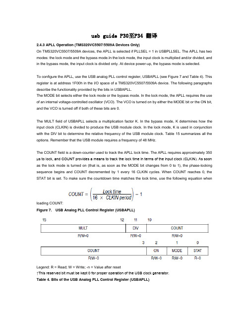
usb guide P30至P34 翻译2.4.3 APLL Operation (TMS320VC5507/5509A Devices Only)On TMS320VC5507/5509A devices, the APLL is selected if PLLSEL = 1 in USBPLLSEL. The APLL has two modes: the lock mode and the bypass mode.In the lock mode, the input clock is multiplied and/or divided, and in the bypass mode, the input clock is divided only. At device power-up, the bypass mode is selected.To configure the APLL, use the USB analog PLL control register, USBAPLL (see Figure 7 and Table 4). This register is at address 1F00h in the I/O space of a TMS320VC5507/5509A device. The following paragraphs describe the functionality provided by the bits in USBAPLL.The MODE bit selects either the lock mode or the bypass mode. In the lock mode, the APLL requires the use of an internal voltage-controlled oscillator (VCO). The VCO is turned on by either the MODE bit or the ON bit, and the VCO is turned off if both of these bits are 0.The MULT field of USBAPLL selects a multiplication factor K. In the bypass mode, K determines how the input clock (CLKIN) is divided to produce the USB module clock. In the lock mode, K is used in conjunction with the DIV bit to determine the relative frequency of the USB module clock. Table 15 summarizes all the options. Remember that the USB module requires a frequency of 48 MHz.The COUNT field is a down-counter used to track the APLL lock time. The APLL requires approximately 350 μs to lock, and COUNT provides a means to track the lock time in terms of the input clock (CLKIN). As soon as the lock mode is turned on (that is, as soon as the MODE bit changes from 0 to 1), the phase-locking sequence begins and COUNT decremented by 1 every 16 CLKIN cycles. When COUNT reaches 0, the STAT bit is set. To make sure the countdown time matches the lock time, use the following equation whenloading COUNT:Figure 7. USB Analog PLL Control Register (USBAPLL)Legend: R = Read; W = Write; -n = Value after reset↑This reserved bit must be kept 0 for proper operation of the USB clock generator.Table 4. Bits of the USB Analog PLL Control Register (USBAPLL)15−12 MULT PLL multiply value. MULT + 1 is the multiply factor K. Table5shows how this factor affects the operation of the APLL.0000b K= 10001b K = 20010b K = 30011b K = 40100b K = 50101b K = 60110b K = 70111b K = 81000b K = 91001b K = 101010b K = 111011b K = 121100b K = 131101b K = 141110b K = 151111b K = 16Introduction to the USB ModuleTable 5. APLL Options for the USB Module Clock Frequency↑ K = MULT + 1↕ The USB clock frequency must be 48 MHz for proper operation of the USB module.2.4.4 Idle Mode ConsiderationsIdling the USB module does not idle the USB clock generator. Doing this simplyprevents the USB module clock signal from driving the USB module.Both the DSP clock generator and the USB clock generator are part of the CLKGEN idledomain. If the IDLE instruction deactivates the CLKGENdomain, both clock generators stop running.3 USB Buffer Manager (UBM)When data is to be moved to or from the buffer RAM, the UBM accesses oneof the following endpoint buffers in the buffer RAM:Each general-purpose endpoint can be configured to have a single buffer (X)or a double buffer (two buffers, X and Y). This is controlled by the double buffermode (DBUF) bit in USBxCNFn. If there are two buffers, the UBM keeps trackof which buffer to use. If the endpoint is in the non-isochronous mode, the UBMuses the X buffer for a DATA0 packet and the Y buffer for a DATA1 packet.Each of the endpoint buffers is associated with a programmable count registerof the following format:The NAK bit corresponds to the negative acknowledgement (NAK) of the USBprotocol. If the NAK bit is set (NAK = 1), the SIE sends a NAK in response toa host request to that particular endpoint. The UBM does not access the bufferuntil NAK is cleared (NAK = 0).译文:2.4.3 APLL 操作(只有TMS320VC5507/5509A设备)在TMS320VC5507/5509A设备中,如果PLLSEL= 1在USBPLLSEL中则APLL被选择。
___________________________________DS3231 ӊĂ I 2C (RTC)Lj ԣ (TCXO) ă Ҫ Lj ү ă լ LjԌ դ ăDS3231 LjԳ 16 Ă300mil SO ăRTC ү Ă Ă Ă Ă Ă ă 31 Lj LjҪ ԣխă 24 AM /PM 12 ă Ӭ Ӭ Ԓ ă I 2C ăĂ ԣխ Ӕ V CC Lj Ռ Ă LjԌ Ӥ ӄ ă LjRST Ѣ Lj դ ԩ ă___________________________________ӹGPS___________________________________♦0°C +40°C ±2ppm ♦-40°C +85°C ±3.5ppm ♦ ӄ ♦ǖ0°C +70°C ǖ-40°C +85°C ♦♦ Ă Ă Ă Ă Ă Ă LjԌ 2100 ԣխ♦ ♦ Ӭ Ԓ♦ (400kHz) I 2C ♦3.3V♦ ǖ ±3°C ♦♦RST 0 ♦ү (UL)DS3231ĂI 2C Ă RTC/TCXO/______________________________________________Maxim Integrated Products1Rev 4; 10/06______________________________ăNbyjn LjNbyjn ă Lj Lj Nbyjn ăLj Nbyjn ǖxxx/nbyjn.jd/dpn/doă#ӹ RoHS Ӷ Lj Lj RoHS ăԳ JESD97 e3 Lj ă Ӷ Đ#đ ӹ RoHS Ӷ ăD S 3231ĂI 2C Ă RTC/TCXO/2ABSOLUTE MAXIMUM RATINGSRECOMMENDED DC OPERATING CONDITIONS(T A = T MIN to T MAX , unless otherwise noted.) (Notes 1, 2)Stresses beyond those listed under “Absolute Maximum Ratings” may cause permanent damage to the device. These are stress ratings only, and functional operation of the device at these or any other conditions beyond those indicated in the operational sections of the specifications is not implied. Exposure to absolute maximum rating conditions for extended periods may affect device reliability.Voltage Range on V CC , V BAT , 32kHz, SCL, SDA, RST ,INT /SQW Relative to Ground.............................-0.3V to +6.0V Operating Temperature Range(noncondensing).............................................-40°C to +85°C Junction Temperature......................................................+125°CStorage Temperature Range...............................-40°C to +85°C Lead Temperature(Soldering, 10s).....................................................+260°C/10s Soldering Temperature....................................See the Handling,PC Board Layout, and Assembly section.ELECTRICAL CHARACTERISTICS(V CC = 2.3V to 5.5V, V CC = Active Supply (see Table 1), T A = T MIN to T MAX , unless otherwise noted.) (Typical values are at V CC =3.3V, V BAT = 3.0V, and T A = +25°C, unless otherwise noted.) (Notes 1, 2)DS3231ĂI 2C Ă RTC/TCXO/_____________________________________________________________________3ELECTRICAL CHARACTERISTICS (continued)(V CC = 2.3V to 5.5V, V CC = Active Supply (see Table 1), T A = T MIN to T MAX , unless otherwise noted.) (Typical values are at V CC =3.3V, V BAT = 3.0V, and T A = +25°C, unless otherwise noted.) (Notes 1, 2)ELECTRICAL CHARACTERISTICS(V CC = 0V, V BAT = 2.3V to 5.5V , T A = T MIN to T MAX , unless otherw.ise noted.) (Note 1)D S 3231ĂI 2C Ă RTC/TCXO/AC ELECTRICAL CHARACTERISTICS(V CC = V CC(MIN)to V CC(MAX)or V BAT = V BAT(MIN)to V BAT(MAX), V BAT > V CC , T A = T MIN to T MAX, unless otherwise noted.) (Note 1)POWER-SWITCH CHARACTERISTICS(T = T to T )DS3231ĂI 2C Ă RTC/TCXO/_____________________________________________________________________5___________________________________________________________________Ѣ___________________________________________________________________D S 3231ĂI 2C Ă RTC/TCXO/6__________________________________________________________I 2CNote 1:Limits at -40°C are guaranteed by design and not production tested.Note 2:All voltages are referenced to ground.Note 3:I CCA —SCL clocking at max frequency = 400kHz.Note 4:Current is the averaged input current, which includes the temperature conversion current.Note 5:The RST pin has an internal 50k Ω(nominal) pullup resistor to V CC .Note 6:After this period, the first clock pulse is generated.Note 7:A device must internally provide a hold time of at least 300ns for the SDA signal (referred to the V IH(MIN)of the SCL signal)to bridge the undefined region of the falling edge of SCL.Note 8:The maximum t HD:DAT needs only to be met if the device does not stretch the low period (t LOW ) of the SCL signal.Note 9: A fast-mode device can be used in a standard-mode system, but the requirement t SU:DAT ≥250ns must then be met. Thisis automatically the case if the device does not stretch the low period of the SCL signal. If such a device does stretch the low period of the SCL signal, it must output the next data bit to the SDA line t R(MAX)+t SU:DAT = 1000 + 250 = 1250ns before the SCL line is released.Note 10:C B —total capacitance of one bus line in pF.Note 11:The parameter t OSF is the period of time the oscillator must be stopped for the OSF flag to be set over the voltage range of0.0V ≤V CC ≤V CC(MAX)and 2.3V ≤V BAT ≤3.4V.Note 12:This delay applies only if the oscillator is enabled and running. If the EOSC bit is a 1, t REC is bypassed and RST immediate-ly goes high.DS3231ĂI 2C Ă RTC/TCXO/_____________________________________________________________________7______________________________________________________________________(V CC = +3.3V, T A = +25°C, unless otherwise noted.)STANDBY SUPPLY CURRENT vs. SUPPLY VOLTAGEV CC (V)I C C S (μA )5.04.03.05010015002.0SUPPLY CURRENTvs. SUPPLY VOLTAGEV BAT (V)I B A T (μA )5.04.03.00.8000.9001.0001.1001.2000.7002.0SUPPLY CURRENT vs. TEMPERATURETEMPERATURE (°C)I B A T (μA )80.060.040.020.00.0-20.00.7000.8000.9001.0000.600-40.0FREQUENCY DEVIATION vs.TEMPERATURE vs. AGING VALUECRYSTAL AGING REGISTER VALUE F R E Q U E N C Y D E V I A T I O N (p p m )966432-64-32-96-40-30-20-100102030405060-128128D S 3231ĂI 2C Ă RTC/TCXO/8_________________________________________________________________________132kHz 2V CC3INT /SQW4RST5–12N.C.13GND14V BAT15SDA 16SCLDS3231ĂI 2C Ă RTC/TCXO/_____________________________________________________________________9_____________________________________________________________________________________________________________DS3231 32kHz ԣ RTC ăTCXO Ă Ը ă -40°C +85°C LjRTC ү ±2 / ăTCXO 32kHz ăRTC / Lj Ӭ Ӭ Ԓ ăINT /SQW Ԓ ă /Ă Ă Ă Ă Ă ă 31 Lj LjԌҪ ԣխă 24 AM /PM 12 ă ԩ I 2C ăԣ Ӕ V CC Lj Ռ LjԌ Ӥ ӄ ăRST ԩѢ LjԌ ă32kHz ă ă Lj ă ԥ Lj ү ăDC ă 0.1μF 1.0μF ăԥ Lj ăԒ ă Lj 5.5V 5.5V ă Lj ү ă (0Eh) INTCN ă INTCN 0 Lj ԒLj RS2 RS1 ă INTCN 1 Lj INT /SQW ( )ă INTCN 1Lj Ԍ ăă / ă V CC V PF Ӷ ă V CC V PF LjRST Ӈ ă V CC մ V PF Ԍ t RST LjRST ԩ ă Ă Ѣ ă Ѣ ă ԩ Ӷ 50kΩ V CC ă ă Ljt REC Ӈ ӚLjRST ă ă ԩӤ ă ăӄ ă 0.1μF 1.0μF ă V BAT LjI 2C Lj ă ԥ V BAT Lj ă Lj UL Lj Ը ǖ/qa/info/ul ă/ ă I 2C / ă ă ă I 2C Lj ԧ ăD S 3231______________________________DS3231 ԩ ăѹ ǖTCXO Ă ĂѢ RTC ă ԩ ă32kHz TCXOTCXO Ҫ Ă ă Lj Փ ӹ Lj AGE Lj ă Ӱ Lj Ljԯ Ҫ AGE Ӱ ăV CC Lj 64 ăԣ V CC Ӕ ă V CC V PF Lj V CC ă V CC V PF V BAT LjDS3231 V CC ă V CC V PF Ԍ V BAT Lj V BAT ăԸ ӹ1ăү LjV BAT V CC V PF Ԍԥ Lj I 2C ă 1 ă V CC I 2C 2 Lj Ռ LjԌ ă Lj (V CC V BAT ) ү ă 64 Ռ Ԍ ăѢDS3231 RST Ѣ ă DS3231ԥ Lj RST ă Ռ ӫ LjDS3231 RST ă ԩ (PB DB ) LjDS3231 RST ă ү LjDS3231 Ռ ă Ռ Ѣ LjDS3231 RST Ԍү t RST ăRST Lj Ҵ ă V CC V PF Lj դ ԩ Ҵ LjԌ RST ă V CC մ V PF LjRST ү 250ms (t REC )Lj ă V CC (Ը ԩ )Lj t REC LjRST Ӱ ăTCXO LjRTC Ă Ă Ă Ă Ă ă 31 Lj Lj Ҫ ă 24 AM /PM 12 ăӬ Ӭ Ԓ ăINT /SQW դ Lj Ԓ ă INTCN ă_____________________________ ӹ1 DS3231 ӹă Lj (12h) Lj 00h ă I 2C START 00h Lj ă Lj ă Ճ Lj Ө ă______________________________I 2CV CC V BAT Lj I 2C ă DS3231 V CC Lj DS3231 I 2C ԥ ԧLj ǖ DS3231 ă Lj SDA SCL Lj DS3231 I 2C ă Lj SCL SDA Ljդ START ăĂI 2C Ă RTC/TCXO/10____________________________ă 1 RTC ă ă Գ lj Ӭ (B C D ) ăDS3231 12 24 ă 6 12 24 ă Lj 12 ă 12 Lj 5 AM /PM Lj PM ă 24 Lj 5 (20 23 )ă 99 00 Lj ( 7 )ăă Lj Ӥ ( Lj 1 Lj 2 Lj )ăԥ ԥ Ճ ăLj ( ) ԩ ă Lj START ԩ ԧă Lj ү ă Ճ Ө ăDS3231ĂI 2C Ă RTC/TCXO/____________________________________________________________________111.ǖ Lj ăD S 3231Lj ă DS3231 Ճ ă Lj Ө LjӤ 1 ă LjԌ Ԓ Lj 1Hz Ԓ 500ms ă___________________________________DS3231Ҫ / ă 1 07h 0Ah ă 2 0Bh 0Dh ă Ӭ ( I N T C N )Lj INT /SQW ă / 7 Ӛ (ӹ2)ă Ӛ 0 Lj /ԯ ă Ӭ Ă Ă Ă ăӹ2 ă ԥѢ ӹ Lj ԥ Ճ ăDY/DT ( / 6 ) 0 5 ă DY/DT 0Lj ă DY/DT 1Lj ăRTC Lj Ӷ 'A1F' 'A2F' 1ă 'A1IE' 'A2IE' 1LjԌ INTCN 1Lj INT /SQW ă Ռ ăĂI 2C Ă RTC/TCXO/12ӹ2. Ӛ_________________________DS3231 ( )Lj Ă Ԓ ă(0Eh)7 ǖ (EOSC)ă 0 Lj ă 1Lj DS3231 V BAT ă Lj ( 0)ă DS3231 V CC Lj EOSC Lj ү ă6 ǖ ӄ Ԓ (BBSQW)ă 1Ԍ DS3231 V BAT Lj V CC Lj Ԓ ă BBSQW 0 Lj V CC Lj INT /SQW Ӱ ă Lj ( 0)ă5 ǖ (CONV)ă 1 Lj LjԌ TCXO ă ă TCXO Ճ Lj Փ BSY ă ԥ ԩ64 ă2ms ԥ BSY ăCONV ү 1Lj CONV BSY Ӱ 0ă CONV ă4 3 ǖ (RS2 RS1)ă Ԓ Lj Ԓ ă ӹ RS Ԓ ă Lj 1 (8.192kHz)ă2 ǖ (INTCN)ă INT /SQW ăINTCN 0 LjINT /SQW ԒăINTCN 1 Lj Lj INT /SQW ( )ă Ӷ Lj INTCN ă LjINTCN 1ă1 ǖ2 (A2IE)ă 1 Lj 2Ӷ (A2F) INT /SQW ( INTCN =1 )ă A2IE 0 INTCN 0 LjA2F ԥ ă LjA2IE ( 0)ă0 ǖ 1 (A1IE)ă 1 Lj 1Ӷ (A1F) INT /SQW ( INTCN =1 )ă A1IE 0 INTCN 0 LjA1F ԥ INT /SQW ă LjA1IE ( 0)ăDS3231ĂI 2C Ă RTC/TCXO/____________________________________________________________________13ԒD S 3231(0Fh)7 ǖ Ӷ (OSF)ă 1ӹ Lj Lj ă Lj 1ă OSF ǖ1) ă2)V CC V BAT ԥ ă3) ӄ LjEOSC ӡă4) ԩ ( Ă )ă ү 1Lj 0 ă3 ǖ 32kHz (EN32kHz)ă 32kHz ă 1 Lj 32kHz LjԌ 32.768kHz Ԓ ă 0 Lj32kHz Ӱ ă Lj 1ăDS3231 ( )Lj32kHz 32.768kHz Ԓ ă2 ǖ (BSY)ă ӹ TCXO ă BSY 1ă 1 ă1 ǖ 2Ӷ (A2F)ă 2Ӷ 1 ӹ2 ă A2IE 1LjԌ INTCN 1Lj INT /SQW ă 0 A2F ă 0ă 1 Ճ ԥ Ӱ ă0 ǖ 1Ӷ (A1F)ă 1Ӷ 1 ӹ 1 ă A1IE 1LjԌ INTCN 1Lj INT /SQW ă 0 A1F ă 0ă 1 Ճ ԥ Ӱ ă_____________________________ ԣխԣխ 8 LjԌ ă 2 ԣ ă Lj LSB ă Ljԣխ ǖ ի Lj Ӕ ӰLj ( CONV ) ă Ֆ 32kHz Lj ăLj Ǘ Lj ăԥ Lj LSB Ӱ (ppm) ԥ ă - ă +25°C Lj LSB ի 0.1ppm ăĂI 2C Ă RTC/TCXO/14ԣխ(10h)___________________ (11h 12h)Գ 10 Ӭ ӹ Lj +0.25°C Ӳ Lj 11h 12h ă Ӭ 2 ԣ ă 8 11h Lj 2 12h ҙ ă Lj 0°C Lj ă ă_________________________I 2CDS3231 I 2C ă ӄ Lj ӄ ă ӄ ӄă ӄ ӄ ӄă Ӥ ӄ Lj ӄ դ (SCL)Ă Lj դ START STOP ăDS3231 I 2C ӄ ă ӄ SCL SDA I/O ă Ӷ (100kHz ) (400kHz )ăDS3231 ă ( 2)ǖ• ԯ ă•Lj Lj Ӥ ү ă Ӱ Lj Ӈ ăLj ǖǖ ү ăǖ Lj Ӱ Lj START ăǖ Lj Ӱ Lj STOP ăǖդ START Lj ү Lj ӹ ă Ӥ Ӱă ăSTART LjԌ STOP ă START STOP Lj ӄ ă Lj 9 ăǖӇ ӄӤ ă ӄӤ Lj ăӄӤ SDA Lj LjSDA ү ă Lj ү Ӥ ă ԥ ӄ ԧ դ Lj ӄ ӄ ă Lj ӄӤ ү ӄ դ STOP ăDS3231ĂI 2C Ă RTC/TCXO/____________________________________________________________________15D S 32313 4 I 2C ă R/W Lj ǖӄ ӄ ă ӄ ӄ ă ă ӄ ă (MSB) ăӄ ӄ ă ӄ ( ӄ )ă ӄ ă ӄ ӄ ă Lj ӄ ă Lj ăӄդ START ĂSTOP ă STOP START ă START Lj ԥ ă (MSB) ăDS3231 ǖӄ (DS3231 )ǖ SDA SCL ă Lj ăSTART STOP ăӄ Lj Ӽă ӄդ START Lj ӄ ă ӄ Ҫ 7 DS3231 Lj 1101000Lj (R/W )ă 0Ljӹ Ճ ă Ԍ ӄ LjDS3231 SDA ă DS3231 ӄĂI 2C Ă RTC/TCXO/162. I 2C3. ӄ ()4. ӄ ( )+ Lj ӄ DS3231ă DS3231 LjDS3231 ă ӄ 0 LjDS3231 ă Lj ă ӄդ STOP ăӄ (DS3231 )ǖ ӄ ă Lj Lj ăDS3231 SDA LjԌ SCL ăSTART STOP ă ӄ Lj Ӽă ӄդ START Lj ӄ ă ӄ Ҫ 7 DS3231 Lj 1101000Lj (R/W )ă 1Ljӹ Ճ ă ӄ LjDS3231 SDA ă DS3231 LjԌ ă Lj ăDS3231Ӥ Ճ ă___________________Ճ ĂPCB Ԧ ѠDS3231 Ҫ Ր ă - ӄLj Ӥ Lj үӨ ăӨ մ Ԓ Lj ăՍ Lj Ө ă N.C.( ) Ӥ ăչ կ Գ չҪ ăӤ Ӷ Ճ Lj ăչ (MSD) Ը IPC/JEDEC J-STD-020Ӷ ă 2 ăDS3231ĂI 2C Ă RTC/TCXO/____________________________________________________________________17D S 3231ĂI 2C Ă RTC/TCXO/18______________________________TRANSISTOR COUNT: 33,000SUBSTRATE CONNECTED TO GROUND PROCESS: CMOS______________________________Theta-JA: +73°C/W Theta-JC: +23°C/W______________________________DS3231ĂI 2C Ă RTC/TCXO/`````````````````````````````````````````````````````````````````````````````( Lj Lj /packages ă)____________________________________________________________________19D S 3231ĂI 2C RTC/TCXO/Nbyjn Nbyjn Lj ăNbyjn Ă ă20___________________Maxim Integrated Products, 120 San Gabriel Drive, Sunnyvale, CA 94086 408-737-7600©2006 Maxim Integrated ProductsNbyjn!Joufhsbufe!Qspevdut-!Jod/ ăEbmmbt!Tfnjdpoevdups!Dpsqpsbujpo! ă____________________________________________________________________Rev 0Ǘ1/05ǖ Ԧ ăRev 1Ǘ2/05ǖ( 1Ă3 ) ±2°C ±3°C ă( 1 ) ă( 2Ă3Ă4 )T A = -40°C to +85°C T A = T MIN to T MAX ă( 8 ) ăRev 2Ǘ6/05ǖ( 1 )Đ UL đǗ ӹ Lj Ӷ S Ǘ N.C. ă( 2 )Đԥ đǗV PF MIN 2.35V 2.45V ă( 3 ) ԣխ Ӷă( 7 ) ӶTOC4ă( 8 ) ӹ X1 ă( 9 ) V CC V BAT ă( 10 ) I 2C ԩ ă( 11 ) 1ǖ Ǘ MSB LSB ă( 13 ) ӹ Ӷ ă( 14 ) Lj Ӱ ԣխ = 00h Ǘ 7 ( ԣխ )ă( 15 ) 7 ( )Ǘ I 2C ԩ ă( 17 ) J-STD-020 Ă Ճ ĂPCB Ԧ Ѡ ԩ ăRev 3Ǘ11/05ǖ( 1 ) RoHS Ӷ ăRev 4Ǘ10/06ǖ( 1 ) ԩ RST UL( 2Ă3 )ECĐV CC > V BAT đ ĐV CC = Active Supply (see Table 1)đă( 6 ) 12Lj ӹ t REC Ճ ă( 7 )TOC 1Ă2 3ă( 9 ) 32kHz ĂV CC RST ă( 10 )ӹ1ǖӶĐPowered By đ ĐActive Supply đǗ ԩ Lj Đ V CC đ ĐV CC V PF đă( 13 ) BBSQW SQW Ǘ( 5 )ǗINT /SQW Đ đă( 14 ) ԩ ԣխԩ Ǘ32kHzĐ ӹ đ Đ đăNbyjn9439 211194ǖ911!921!1421 ǖ121.732262:: ǖ121.732263::。
医疗器械类英语及其缩写DC (direct current)直流电DAMPER 阻尼器DGC (degaussing coil) 消磁线圈DL (delay line )延时线DRIVE 激励、推动DRIVE TRANSF 推动变压器DY (deflection yoke) 偏转线圈EHT (extra -high tension)极高压EMERGENCY-急停装置ERROR AMP (error amplifier)误差电压放大器E-W CORRECTION(east — west correction)东西向校正FBT (fly back transformer) 逆程变压器FILTER 滤波器FLIP FLOP 双稳态触发器FIYEACK BLANKING 回扫消隐FOCUS 焦点FOCUS VR (focus variable rheostat)聚焦电位器f.(fuse) (fuse)保险丝GANTRY-机架G (green) 绿色的GND (ground)接地GREEN CUT OFF 绿枪截止调节GREEN OUT 绿色输出GREY 灰度G - Y MATRIX (G — Y )矩阵H. BLK (horizontal blanking) 行消隐H。
DY (horizontal deflection yoke)行偏转线圈HFC (high frequency choke) 高频扼流圈H。
HOLD (horizontal hold)行同步调节H (L)。
DRIVE (horizontal driver)行推动放大器HLIN (horizontal linearity) 行线性H(L)OUT BOARD 行输出板H 。
M(module)厚膜电路HOR AFC (horizontal automatic frequency control)行自动频率控制HOR DRIVE TRANS 行激励变压器HORIZONTAL 行(水平)扫描部分HORIZ O/P (horizontal out put )行脉冲输出H。
13General Specificationsq External Dimensions; Weight (with I/O module installed)DR231:approximately 438 (W)ϫ291 (H)ϫ336 (D) mm; approximately 13 kg DR232:approximately 438 (W)ϫ291 (H)ϫ301 (D) mm; approximately 9 kg DS400:approximately 336 (W)ϫ165 (H)ϫ100 (D) mm; approximately 2.5 kg DS600:approximately 422 (W)ϫ176 (H)ϫ100 (D) mm; approximately 3.5 kgFor model DR231, the DC power supply option adds 45 mm to the depth and 1.5kg(f) to the weight.q AC Power Supply Rated supply voltage:100 to 240 VAC Usable supply voltage:90 to 250 VAC Rated supply frequency:50/60 Hzq DC Power Supply (/P6 option, only for the DR231 stand-alone model)Rated supply voltage:12 to 28 VDC Usable supply voltage:10 to 32 VDC Terminal:Dedicated connector Note:When both AC and DC power are connected to a DCpower supply model, which of the power supplies is used depends on the voltage of the DC power supplyq Insulation ResistanceAt least 20 M Ω at 500 VDC between the power supply and ground, between each terminal and the ground, and between input terminals q Withstanding VoltageBetween power supply terminal and ground:1,500 VAC (50/60 Hz, 1 min.)Between input/output terminal and ground:1,500 VAC (50/60 Hz, 1 min.)q Normal Operating Conditions Supply frequency:50 Hz ±2% or 60 Hz ±2%Ambient temperature:DR231, DR232 0 to 50˚C (FD operation 5 to 40˚C)DS400, DS600Panel mount –10 to 60˚CDesk-top –10 to 50˚CAmbient humidity:20 to 80% RH (between -10 and 40˚C)q Safety StandardsCSA C22.2 No. 1010.1-92, IEC1010-1:1995, EN61010q EMI StandardEN55011:1991 Group 1 class A q EMC Standard EN50082-2:1995System Configuration q Configuration Method DR231:Configure a system with this model by specifying necessary options, such as the input and communications functions, according to the model code when ordering.DR232:Configure a system with this model by combining one or more of the modules and subunits listed below.Connecting Modules and Subunits (DR232)q Standard Modules and Software for System ConfigurationThe following modules and software can be installed in a main unit and subunit to configure a data acquisition system.Input Modules:Universal (DCV, TC, RTD and DI), DCV/TC/DIdedicated, power monitor, strain, pulse, direct current (mA) and digital inputConnectable to DS400 and DS600Communications Modules :Ethernet, GP-IB, RS-232C and RS-422A/485Connectable to DR232 main unitAlarm Contact Output Modules: 4 contacts (C contact: NO-C-NC) and 10 contacts (Acontact: NO-C)Connectable to DR232 Main unit or DS400 and DS600DI/DO Modules:Two alarm output contacts (NO-C-NC) and fail outputConnectable to DR232 Main unit or DS400 and DS600Up to 1 module/1 system can be connected.Extension Modules:Interfaces for remote power supplyOne extension module can be connected to each DS400 and DS600.(should be used with extension base units)Software:DAQ 32(standard software)DAQ 32 Plus (optional software)q Types and Number of Modules That Can Be Connected DR231:Specify the types of modules and the numberaccording to the model code.DR232:Communications module, DI/DO module or alarmcontact output moduleDS400/600Input module, alarm contact output modules, DI/DOmodule and extension modulesFour or six modules can be connected.q Connection of Subunits DR231:Cannot be connected.DR232:Up to 6 subunits can be connected. One subunit canbe installed on the rear panel by screws.Input Sectionq Number of Input Channels DR231:10 to 30 channels (Specify the number of channelswhen ordering.)Power monitor input option: 2 or 6 channelsDR232:0 channel. Expandable up to 300 channels byconnecting subunits.q Types of Input Modules DR231:Universal (DC voltage, thermocouple, RTD andcontact), DCV/TC/DI dedicated (specify the types when ordering), power monitor optionDR232:Universal (DC voltage, thermocouple, RTD andcontact), DCV/TC/DI dedicated, power monitor,strain, pulse, direct current (mA) and digital input moduleq Measurement Range:See the specifications for each input module.Specificationsq Measurement Interval:0.5, 1, 2, 3, 4, 5, 6, 10, 12, 15, 20, 30 and 60 seconds DR231:Maximum of 2 s per 30 channels DR232:Maximum of 500 ms per 300 channels (including the subunit)The measurement interval is dependent on the slowest input module if input modules of different measurement intervals are connected at the same time.q A/D Integration PeriodManual selection or automatic switchover between 20 ms (50 Hz), 16.7 ms (60Hz) and 100 ms (10 Hz)Minimum measurement interval when the 100-ms integration mode becomes:DR231:30 channels: 6 seconds DR232: 4 seconds per 300 channels (including the subunit)(depends on the modules and number of channels)Recording section (DR231/232 main unit)q Recording MethodRaster scan method, 10-color wire dot recording q Number of Recording Points300 points maximum (stand-alone model: 30 points + AC 6 points)q Recording PaperEffective recording width :250 mm (for analog trend measurement)q Analog recording color (You can specify a color for each channel.)Purple, red, green, blue, brown, black, navy blue, yellow-green, red-purple,orangeq Analog Recording Interval FIX:Recording takes place at the specified measurementinterval between 2 and 60 seconds (not all measured values are sampled for analog recording in case of the 0.5- and 1-second measurement intervals)AUTO:Linked to recording paper feed speed q Recording Paper Feed Paper feed speed: 1 to 1,500 mm/hour Display Section q Display Section Display:VFD display (5 x 7 dot matrix, 3 lines)Number of characters:22 characters (large/1 line), 40 characters (2 lines)Memory Function Section q Memory Media3.5-inch floppy disk drive with 512 kB SRAM buffer memory q Data Capacity10 data/ch to 50 kdata/ch(Total data memory should be less than total memory length.)q Applicable dataSetting values, measured values and computed values except report calculating values q Memory Mode BinaryCan be converted to ASCII (CSV) format for copying buffer memory data to floppy disk.q Sample RateSynchronized with the measurement interval of the recorder unit, or synchronized with event.Alarmsq Number of SettingsUp to four settings can be made for each channel.q Kinds of AlarmsUpper/lower limit, difference upper/lower limit, upper/lower limit of percentage change, upper or lower limit only for the results of computation Percentage change alarm time interval: 1 to 15 scans q Number of Alarm Output Points DR231:12 maximum (alarm option: 10; DI/DO option: 2)DR232:300 in total Standard Computation Functions q Kinds of ComputationDifference between arbitrarily selected channels, linear scaling, moving average, pulse integration Scalable range:DC voltage, thermocouple, RTD, contact Scaling range:–30,000 to +30,000Moving average: 2 to 64 scans Pulse integration:Effective when a pulse input module is recognized(up to 60 channels)Fail, Chart End Output(DR expandable model. The DR stand-alone model uses the /R1 option.)Functions:Refer to the DI / DO modules.q Number of Computation Channels DR231:30 channels maximum DR232:60 channels maximum q KindsRemote RJC, four arithmetic operations, SQR (square root), ABS (absolute value), LOG (common or natural logarithm), EXP (exponential), statistics processing (CLOG, TLOG), logic (AND, OR, NOT, XOR), relative computation,previous data reference CLOG:Mathematical processing within a group of data thatwas measured at the same time (total, maximum,minimum, average, max. - min.)TLOG:Mathematical processing of data from a certainchannel over a period of time (24 hours maximum)(total, maximum, minimum, average max. - min.)Report Function (/M3)Instantaneous values of measured data, as well as maximum, minimum, average and total, for each hour, day or month are printed in tabular form on recording paper. Analog recording is interrupted while a report is being made.Report calculation channels :Up to 60 channels Note:This function does not allow the results of the reportand computing function to be saved on floppy disks.(Thus, to be able to transfer the results to a personal computer, the DP380 report software is needed.Note that the DP380 software cannot be run simultaneously with the DAQ32 or DAQ32Plus software package.)Power Monitor Options (/N7, /N8)q Applicable models and outline specificationsDR231 stand-alone model (For the DR232, the power monitor module is soldseparately.) Refer to the power monitor module.GP-IB Communications Option (/C1)q Applicable models and outline specificationsDR231 stand-alone model (For the DR232, the GP-IB module is sold separately.)Refer to the GP-IB module.RS-232C Communications Option (/C2)separately.) Refer to the RS-422A/485 module.Ethernet Communications Option (/C7)q Applicable models and outline specificationsDR231 stand-alone model (For the DR232, the Ethernet module is sold separately.) Refer to the Ethernet module.Alarm Contact Output Option (/A4)q Applicable models and outline specificationsDR231 stand-alone model (For the DR232, the alarm contact output module is sold separately.) Refer to the alarm output module.Recorder Function Remote Control Option (/R1)q Applicable models and outline specificationsDR231 stand-alone model (For the DR232, the DI/DO module is sold separately.)The DR232 expandable model incorporates fail and chart-end outputs as standard features. Refer to the DI/DO module.q Normal Operating Temperature/Humidity RangeUniversal, DCV/TC/DI input modules:–10 to 60˚C, 20 to 80% RH(non condensing)mA, power monitor, strain, pulse input modules :0 to 50˚C, 20 to 80% RH(non condensing)q Withstanding Voltage Between input terminals:1,000 VAC (50/60 Hz) for one minuteStrain input: 50 VDC (50/60 Hz, 1minute, except DU500-14)Between input terminal and ground:1,500 VAC (50/60 Hz) for one minute Universal Input Modules DCV/TC/DI Input Modulesq General Specifications Input method:Floating imbalance input, and inter-channel isolation RTD and pulse inputs are of the same potential within the same input module.A/D resolution:±20,000A/D integration time:Manual selection or automatic switchover between20 ms (50 Hz), 16.7 ms (60 Hz) and 100 ms (10 Hz)Measurement Range DC voltage range:20 mV to 50 V Thermocouple:R, S, B, K, E, J, T, L, U, N, W, KP-Au7Fe RTD:Pt100, JPt100, Ni100, Ni120, Cu10, and J263*B Contact input:Voltage-free contact input or voltage inputMixed input is allowed for DC voltage, thermocouple, RTD and contact inputs.(For an DCV/TC/DI input module, RTD input is not allowed.)Measurement accuracy:±(0.05% of reading + 2 digits)(at 2-V range, 23 ±2˚C and 55 ±10% RH)Noise rejection:By means of integrating A/D, low-pass filter or movingaverageBurnout:Detected within thermocouple-input range DC Current Input Modulesq General Specifications Input method:Floating imbalance input, and inter-channel isolation Shunt resistor (100 Ω) is pre-installed.A/D resolution:±20,000A/D integration time:Manual selection or automatic switchover between 20 ms (50 Hz), 16.7 ms (60 Hz) and 100 ms (10 Hz)Measurement range (resolution):±20 mA (1 µA)Noise rejection:By means of integrating A/D, low-pass filter or moving averagePower Monitor ModulesInput method:Transformer isolationMeasured variables:Six items can be selected from the following: RMS value of AC voltage/current, active power, apparent power, reactive power, frequency, power factor and phase angle (There is a restriction in combining selected items.Measurement range (resolution):Voltage:250 V (0.1 Vrms), 25 V (0.01 Vrms)Current:5 A (0.001 Arms), 0.5 A (0.001 Arms)Measurement accuracy:±(0.5% of span when RMS V and A are measured)Measured frequency:45 to 65 Hz (all channels must have the same frequency)Crest factor:Up to 3Power integration:Calculated by /M1 (computation functions) option./M1 must be specified for the DR230.Strain Measurement Modulesq General SpecificationsMeasurement range (resolution):2,000 µε (0.1 µε) ,20,000 µε (1µε) ,200,000 µε (10 µε)Built-in bridge resistance :120 Ω, 350 Ω, or none (for an external bridge box)Wiring:1/4 bridge, 1/2 bridge (neighbor), 1/2 bridge (opposite),full bridgeApplicable gaugeresistance :1/4 or 1/2 bridge:120 or 350 ΩFull bridge:100 to 1,000 ΩBridge voltage:Fixed at 2 V Gauge factor: 2.00 (with scaling function)Strain balance:Electronic auto-balancing (can be turned on or off ineach module) within ±10,000 µε (1/4 bridge )Pulse Measurement ModulesInput method:Shared common line within the same moduleType of input:Non-voltage contact or open collector (TTL or transistor)Measurement modesRATE (count value instantaneous mode):The number of pulses input during the most recent one-second period of measurement is output as the scale set value.GATE (ON time instantaneous mode):The ON (make)/OFF (break) state (ON = 1, OFF = 0)of the contact input during the most recent one-second period of measurement is output as the scale set value.Pulse integration:The computation function is used when integratingeither the count value each second or the ON period.Computation formula:TLOG.PSUM (XXX)Number of computation channels:Max. 60 channelsMax. count value/ON period:99999999(/M1 (computation option) need not be specified for the DA100 or DR recorder main unit. Pulse integration can be used automatically when a pulse module is recognized.)Maximum input frequency : 6 kP/s (10 P/s for voltage-free contact)Filter:For rejection of chattering up to 5 ms (can be turnedon and off for every channel)Digital Input Moduleq General Specifications Input method:Unbalanced floating-point, with channel-to-channel isolation (individually separated channels)Measuring range:Voltage input 2.3 V or less 02.5 V or greater (1)Voltage-free contact input Off (open) 0On (closed) (1)Maximum input voltage range:Voltage input ±60 V DC Voltage-free contact input ±10 V DC q General Specifications Output mode:Selection between excitation and non-excitation,output hold and non-hold and AND and OR modes Re-breakdown re-alarm: Maximum of 6 contacts can be selected.Contact capacity:250 VDC/0.1 A (resistive load),30 VDC/2 A (resistive load),250 VAC/2 A (resistive load)DI/DO Modulesq Common Specifications Model:DT100-11The DR232 expandable model incorporates fail and chart-end output as standard features. (Up to 1 module can be connected to the DR230 expandable model.)q Alarm Contact Output Number of outputs:2Contact mode: C contact—NO-C-NC terminal Contact capacity:250 VDC/0.1 A (resistive load),30 VDC/2 A (resistiveload),250 VAC/2 A (resistive load)q Chart End Output Outline of functions:The chart end output terminal is energized if therecording paper in the recorder breaks.The DR stand-alone model uses the /R1 option.Contact mode:Make contact (NO-C). Cannot be switched betweenexcited and non-excited.Contact capacity:250 VDC/0.1 A (resistive load),30 VDC/2 A (resistiveload),250 VAC/2 A (resistive load)q Fail Output Function:If an abnormality is found in the total system, the failoutput terminal is de-energized.Output mode:Make contact (NO-C). Cannot be switched betweenContact capacity:250 VDC/0.1 A (resistive load),30 VDC/2 A (resistiveload),250 VAC/2 A (resistive load)q Remote Control Signal InputElectrical and mechanical specifications:Based on EIA RS-422A and EIA RS-485 Connection method:Multi-pointAddress: 1 to 31Communications format:Half-duplex, 4-wire method/2-wire method Synchronization:Start-stop synchronization (synchronization bymeans of start and stop bits)Baud rate: 300, 600, 1200, 2400, 4800, 9600, 19200 or 38400 bps Transmission distance:Maximum of 1200 mConnector:6-screw terminalEthernel ModulesNetwork configuration:Ethernet (10Base-T)10Base-T modular connector:1Baud rate:10 MbpsCommunication protocol:TCP, UDP, IP, ARP or ICMPInput data:ASCIIOutput data:ASCII or binary s Model and Suffix CodesDR230 Stand-alone modelq, / C, / A4 and / R1 options is determined according to the specified channel number.10 ch: All options can be specified.20 ch: All of them can be specified.30 ch: 3 of them can be specified.DR230 Expandable modelqq The extersion cable must be ordered separately when the subunit is specified.Subunit: DS400, DS600Configuration example of the expandable modelq100 ch, 0.5 s universal input, with RS-232C and 20-ch alarm output•DR230 expandable main-unit: DR232 × 1•Sub unit: DS600 × 2•Universal input module: DU100-11 or -12 × 10•Communication module: DT300-21 (RS-232C) × 1Input modulesSoftwareand neither can the combination of the DP350 enhanced multi-functional data logging software, DP380 report software and DP800 InTouch for DARWIN software.Optional accessoriesExcel, Windows, MS and MS-DOS are registered trademarks of Microsoft Corporation, USA.IBM and IBM PC/AT are registered trademarks of International Business Machines Corp.Lotus 1-2-3 is a registered trademark of Lotus Development Corporation.AT-GPIB and GPIB-98 Turbo are registered trademarks of National Instruments.Ethernet is a registered trademark of Xerox Corporation.Other company and/or product names are registered trademarks of the respective companies.External Dimensions (DR232 with DS600 subunit on the rear panel )。
DS3234是低成本,高精度spi总线实时钟,带有集成温补晶振,包含一个精确的温补基准电压和比较器来监控Vcc,当Vcc下降至失效电压Vpf,设备维持RST低电平,并且禁止读写访问芯片,当Vcc下降至低于Vpf和Vbat。
RST脚被当作一个按钮输入,产生一个复位信号。
当到设备的主电源被中断,设备切换到备用电源,并保持精确的时钟。
内置的晶振提高了设备长期的精确性,也缩减了生产线上的零件数量。
DS3234可用在商业和工业温度范围,并且提供在一个工业标准的300mil,20pin,sop封装。
DS3234也集成了256字节的有电池后备的SRAM。
在主电掉电,内容由连接到Vbat脚的电源维持,继续计时。
RTC保持秒,分,小时,天,日期,月份和年信息。
在月份结尾的日期自动调整少于31天的月份。
包括修正闰年。
时钟运行在24小时或带有AM/PM的12小时两种格式。
两个可编程每日定时器和一个可编程方波输出被提供给用户。
地址和数据由SPI双向总线串行传输。
此上位机通过AVR单片机访问DS3234内部SRAM数据,进行读写时钟数据,完成直观的芯片功能测试.
在用它之前没找到任何中文资料
以下为俺生成N根白头发译成的中文版datasheet,也算报答MAXIM白送给俺两个DS3234
可作参考,不保证绝对正确性,如果官方有中文版,请参考官方的版本。