GrIPD A Graphical Interface Editing Tool and Run-time Environment for Pure Data
- 格式:pdf
- 大小:29.68 KB
- 文档页数:3
WHY USE ARCGIS ENGINE?Many users require focused, lightweight access to GIS, embedded in an application or as a standalone application. For example, users may need much less than ArcView yet still require access to sophisticated GIS logic in their application. In cases where users need focused, customized access to GIS, ArcGIS Engine provides a lower-cost, lightweight option. ArcGIS Engine is used to: • Embed GIS logic in custom applications. • Efficiently build and deploy GIS applications. • Provide access to advanced GIS logic from simple applications. • Embed GIS logic and maps in other applications. • Build cross platform applications with C++ or Java.96 • What is ArcGIS?7Mobile GIS: ArcP cPad ArcPad and devices devices97MOBILE COMPUTINGMobile computing is creating fundamental changes by adding the ability to take GIS with you into the field and interact directly with the world around you. Mobile GIS comprises the integration of a number of technologies: • GIS • Mobile hardware in the form of lightweight devices and ruggedized field PCs • GPS • Wireless communications for Internet GIS access Traditionally, the process of field data collection and editing has been time-consuming and error-prone. Geographic data has traveled into the field in the form of paper maps. Field edits were performed using sketches and notes on paper maps and clipboards. Once back in the office, these field edits were deciphered and manually entered into the GIS database. The result has been that GIS data has often not been as up-to-date or as accurate as it should have been. Consequently, GIS analysis and decisions have been delayed. Recent developments in mobile technologies have enabled GIS information to be taken into the field as digital maps on compact, powerful mobile computers, providing field access to enterprise geographic information. This enables organizations to add real-time (and near real-time) information to their enterprise database and applications, speeding up analysis, display, and decision making by using up-to-date, more accurate spatial data. Many field-based tasks utilize geographic information that has benefited from the increased efficiency and accuracy of mobile GIS, including: • Asset inventory, which usually requires field data collection or mapping • Asset maintenance, which usually requires updates to attribute information and geometry of GIS features • Inspections, typically involving field assets or legal code compliance • Incident reporting—for example, spatially recording accidents or events • GIS analysis and decision makingThese field-based tasks are common to many GIS applications, such as utility inspections and maintenance, mapping of natural resources, mineral exploration, recording of accidents, inspection of compliance to local government codes, mapping of wildfires, and many more. Some of the field-based tasks involve fairly simple operations that require simple geographic tools. In contrast, some field-based tasks involve complex operations and, consequently, require sophisticated geographic tools. ArcGIS includes applications that meet the requirements of both of these needs: • ArcPad focuses on field tasks that require relatively simple geographic tools. These tasks are typically performed on handheld computers (running Microsoft Windows CE or Pocket PC). • ArcGIS Desktop and ArcGIS Engine focus on field tasks that require more sophisticated geographic tools. These tasks are typically performed on high-end Tablet PCs. Field GIS also relies heavily on application customization to simplify mobile work tasks as well as wireless access to real-time data feeds from central GIS Web servers, such as sites deployed with ArcIMS and ArcGIS Server.98 • What is ArcGIS?ARCPAD: MAPPING AND GIS FOR MOBILE SYSTEMSESRI’s ArcPad software is mobile mapping and GIS technology for mobile Windows devices. ArcPad provides database access, mapping, GIS, and GPS integration to field users via handheld and mobile devices. Data collection with ArcPad is fast and easy and improves fieldbased data validation and availability.COMMON ARCPAD FUNCTIONSEXAMPLES OF ARCPAD APPLICATIONSArcPad is typically used for building specialized mapping and data collection applications. The following list includes examples of ArcPad applications: • Street sign inventory • Power pole maintenance • Meter reading • Road pavement management • Military fieldwork • Mineral exploration • Habitat studies • Toxic inventory • Crop management • Property damage assessment • Field surveying • Incident reporting and inspection • Real-time wildfire boundary mapping • Refuse container inventory • Wildlife tracking • GIS data validationARCPAD APPLICATION BUILDER• Support for industry-standard vector and raster image display • ArcIMS client for data access via wireless technology • Map navigation, including pan and zoom, spatial bookmarks, and center on the current GPS position • Data query to identify features, display hyperlinks, and locate features • Map measurement: distance, area, and bearings • GPS navigation to connect a GPS and let ArcPad guide you • Simple editing: creating and editing spatial data using input from the mouse pointer, pen, or GPS • Mobile geodatabase editing: checking out, converting, and projecting your GIS data using ArcGIS; editing in the field with ArcPad, and posting changes back to the central GIS database • Application development to automate GIS fieldworkCreating a personalized and custom field solution for mapping, data collection, and updates is essential for mobile GIS. ArcPad users are able to customize ArcPad and build focused applications using ArcPad Application Builder. ArcPad Application Builder runs on Windows computers. Developers build custom applications within this environment and can deploy them on numerous ArcPad devices in their organization.ArcPad supports numerous Windows CE and Pocket PC devices.Mobile GIS: ArcPad and devices • 99ARCGIS DESKTOP AND ARCGIS ENGINE ONTABLETPCMany users have requirements for high-end field computers with built-in GPS. These field computers run the full Windows operating system and are used for remotely performing many advanced computer-based tasks. In recent years, Microsoft has introduced a new operating system called the Microsoft Windows XP Tablet PC Edition, which enables many innovative features such as pen-based computing, digital ink technology, and enhanced mobility functions. ArcGIS Desktop running on Tablet PCs is a powerful mobile platform for advanced GIS field computing. Tablet PC technology enables users to redline designs, capture accurate field measurements using GPS, and leverage the comprehensive functionality of ArcGIS and the geodatabase in the field.OVERVIEW OF TABLET PCARCGIS DESKTOP AND ARCGIS ENGINE ON THE TABLET PCArcGIS includes a series of tools for Tablet PCs that enable users to take advantage of the Tablet PC’s innovative features—pen-based computing, digital ink technology, and enhanced mobility functions as well as the rich mapping and data compilation capabilities of ArcGIS. The primary focus at ArcGIS 9 has been on supporting ArcGIS Desktop and its rich mapping and editing tools on Tablet PCs. Tablet PC capabilities also work well with ArcGIS Engine. For example, ArcGIS Engine users can use the pen interface to highlight and query features, add and change attribute values, and interact with their custom applications. The ArcGIS Desktop application ArcMap has been extended with a Tablet PC toolbar that integrates digital ink technology with ArcGIS. Using the Tablet toolbar, users can access the ink tool to create notes or sketch diagrams and tie them to a geographic location. The ink tool can also be used to highlight features on a map and sketch shapes that can be used to perform GIS editing tasks. Tablet tools make use of ink technology such as gestures and text recognition.A key capability of Tablet PC is the use of a pen-based interface for computer interaction, sketching, and capturing notes. These activities are based on a technology called digital ink. Digital ink is created through sketching and can be converted to text using the text recognition engine, added to the edit sketch for any editing task, or stored as a graphic in datasets. The Tablet PC platform is commonly used in four ways: • Tablet PC as a notebook computer: The Windows XP Tablet PC Edition is a superset of the existing Windows XP operating system. • Tablet PC pen-based technology: The Tablet PC lets you drive the Windows XP operating system and all Windows-based applications using a digital pen instead of a mouse. For example, in ArcGIS, the digital pen can be used to push buttons on toolbars and draw on the map. • Windows XP speech recognition: The speech recognition functionality is embedded within the Tablet PC input panel and can be used with ArcGIS for dictation functions. • Tablet PC digital ink technology: Pen interfaces are used for sketching with Tablet PCs. Digital ink, created through sketching, can be converted to text using the text recognition engine, added to the edit sketch for completion of a current editing task, or stored as a graphic.The ArcGIS mapping application ArcMap includes a toolbar that integrates digital ink technology with ArcGIS. Using the Tablet toolbar, you can access the Pen tool to create notes or sketch diagrams and tie them to a geographic location.The Tablet tools for ArcGIS Desktop add a graphic element called an ink graphic. Ink graphics are stored along with other graphic elements and text in the map’s graphics layer or as annotation in the geodatabase. Therefore, you100 • What is ArcGIS?can create ink using ArcGIS and choose whether to store it in the map or the geodatabase you are editing.TABLET PC CUSTOMIZATIONMobile GIS requires focused application designs and customization to build productive, simple user interfaces for field-workers. Since ArcGIS is being used, the same customization and ArcObjects programming work done for all of ArcGIS can be leveraged for building and deploying Tablet PC applications.Sketches and notes created in ArcMap on the Tablet PC are geographically referenced and can be saved as map graphics or as annotation in the geodatabase.Here is a list of some of the Tablet toolbar functions: • Pen tool creates new ink graphics on the map. • Highlighter tool draws transparent ink on the map for highlighting features. • Erase tool removes strokes of ink from the map display. • Finish Ink Sketch command creates new ink graphic elements from the ink that is being collected on the map. • Clear Ink Sketch command removes all ink that is being collected. • Add Ink To Sketch command lets ink be used to complete the current editing task (such as creating new features). • Recognize Ink Graphic command converts selected ink graphics written with the Pen tool into text elements. • Reactivate the Selected Ink Graphic command creates a new ink sketch from the selected ink graphic so it can be edited using the Pen or Highlighter tool. • Find Ink Graphic tool searches the map or a geodatabase for ink based on its recognized text.Mobile GIS: ArcPad and devices • 1018Future Future GIS trends trends103FUTURE GIS TRENDSGIS will continue to grow and evolve. Its evolution will be based on a series of fundamental GIS characteristics as well as computing and Internet trends. Here are some of the important factors that exert an influence: • GIS has been evolving from a database and data sharing approach to a knowledge approach. A GIS is much more than a database. In addition to GIS datasets, GIS users work with maps and globes, geoprocessing and work flow models, and multipurpose GIS database designs (data models). All of these are documented using metadata to enable publishing and sharing of geographic knowledge. • GIS systems are becoming federated, and geographic knowledge is being shared on the Web. Users will also share and replicate updates between their systems, and Internet GIS will increase in sophistication and use. Increasingly distributed GIS capabilities will be thought of as an integral part of a GIS platform. • In the past few years, GIS catalog portals have been providing centralized access to distributed information sets at many organizations. Over time, GIS portals will also help integrate distributed GIS data management and use.• Individual GIS systems continue to be increasingly connected in a loosely-coupled manner on the Web. The Internet is fast becoming the framework for integrated access to geographic knowledge that will continue to be built, maintained, and published at many independent GIS nodes. This vision has been described over the past decade as a National or Global SDI. Integrative technologies to implement this vision are growing. • GIS systems are inherently distributed. Users rely on one another for information sharing and use. Distributed GIS is much more than distributing GIS databases and dataset copies. It will also be about distributed collaboration on all GIS tasks. In addition to GIS publishing and data sharing, users will leverage the Internet to compile, apply, and manage geographic knowledge. This final chapter presents some of these key trends and provides a context for how GIS will grow and evolve in the coming years. The ArcGIS platform has been built to address and evolve support for these key trends.104 • What is ArcGIS?INTELLIGENT GIS“GIS is evolving from a database approach to a knowledge approach.” —ESRI President Jack Dangermond, July 2003 Historically, humans have learned to express knowledge and share it through many abstract forms. These abstractions, summaries of the larger body of knowledge, have been continually used to explain the human experience and collective understanding. Abstractions— such as text, hieroglyphics, language, mathematics, music and art, drawings, images, and maps—are used to record and communicate culture and civilization from generation to generation.Statistical Analysis & Tabular Data Digital g it l Movies/Sound M d Text Tex Tex e ext Processing P s Computer p ter er Models s Image I Processing Proc r roc Mobile le e Document ocument c Management Management Virtual t tual Reality eality a yStatistics Language Math/ScienceX=Y-Z NaCl 2Digital technology is increasingly used to capture everything we know.HieroglyphicsModelsGeography has traditionally provided an important framework and a language for organizing and communicating key concepts about the world. GIS provides a comparatively new mechanism for capturing geographic knowledge into five basic elements: • Maps and globes Interactive views of geographic information with which to answer many questions, present results, and use as a dashboard for real work • Geographic datasets File bases and databases of geographic information— features, networks, topologies, terrains, surveys, and attributes • Processing and work flow models Collections of geoprocessing procedures for automating and repeating numerous tasks • Data models The schema, behavior, and integrity rules of geographic datasets • MetadataCrosier, S. J., Goodchild, M., et al. (2003) “Developing an Infrastructure for Sharing Environmental Models” Environment and Planning B: Planning and Design 2003, volume 30(4) July, pages 487 – 501 Crosier, S. J. (2001) "Defining Space - A Metadata Approach" Of Significance 2001, Volume 3(2) pages 26 – 31 Hill, L. L., S. J. Crosier, et al. (2001). A Content Standard for Computational Models. D-Lib Magazine. 7. (Available: /dlib/june01/ hill/06hill.html)Music/Art DrawingsMapsImagesHumans use many abstractions to express and communicate the collective understanding of the earth and its systems. Geography provides a universal framework for abstraction and communication about “place”.In the digital computing age, everything known has begun to be captured and shared across networks (the World Wide Web). These knowledge collections are rapidly becoming digitally enabled. Simultaneously, GIS is evolving to help humans better understand, represent, manage, and communicate many aspects of the earth as a system.Documents describing the other elements—a document catalog enabling users to organize, discover, and gain access to shared geographic knowledgeFuture GIS trends • 105106 • What is ArcGIS?These five elements, along with comprehensive GISsoftware logic, form the building blocks for assemblingintelligent geographic information systems. Intelligent GISmakes it possible to digitally encapsulate geographicknowledge. These elements provide a foundation foraddressing many challenges using GIS (for example,improvements in efficiency, intelligent and informeddecision making, science-based planning, resourceaccounting, evaluation, and communication).Intelligent GIS will enable the capture and sharing ofgeographic knowledge in many forms—as advanced GISdatasets, maps, data models, the expertise of professionalswho have developed standardized work flows, andadvanced models of geographic processes. Intelligent GISwill also enable the building and management ofknowledge repositories that can be published for others touse.ArcGIS and the geodatabase were engineered to supportthis knowledge-based approach. They enable the creation,use, management, and sharing of all five geographic knowledge elements.GIS SoftwareCrosier, S. J., Goodchild, M., et al. (2003)“Developing an Infrastructure for SharingEnvironmental Models” Environment and PlanningB: Planning and Design 2003, volume 30(4) July,pages 487 – 501Crosier, S. J. (2001) "Defining Space - A MetadataApproach" Of Significance 2001, Volume 3(2)pages 26 – 31Hill, L. L., S. J. Crosier, et al. (2001). A ContentStandard for Computational Models. D-Lib Magazine.7. (Available: /dlib/june01/hill/06hill.html)Data ModelsGlobes Geodata SetsMetadataGIS abstracts geography into five basic elements used for representing geographicknowledge. These elements, along with advanced software, provide the buildingblocks for intelligent GIS.Future GIS trends • 107GIS users have long relied on collaborative efforts for datasharing and use. Today, there is widespread recognitionthat the datasets and tables in most geographicinformation systems come from multiple organizations.Each GIS organization develops some, but not all, of itsinformation content. At least some of the layers comefrom outside the organization.The most important standards for GIS will be based onmany of the emerging computing and Web standards. TheInternet already plays a critical role in distributed GIS andwill continue to do so. Emerging technology frameworkswill help immensely. Modern Web services frameworksbased on XML and SOAP will enable independent systemsto interoperate across the Web. Emerging frameworks forwireless communications and browser-based access tocentral enterprise applications will mean that GIS can bedistributed in any computer environment to many users.Evolving GIS standardsIn particular, Web services will provide a loosely coupled enterprise computing environment that enables users to connect to information and GIS functionality over the World Wide Web from their desktops, Web browsers, and mobile devices. GIS logic will be deployed in all appropriate technical frameworks.Most important, Web services can also be used to integrate many individual systems, regardless of their internal architectures.Web services provide a new type of interoperability for integrating many systems.108 •What is ArcGIS?Most GIS data sharing activities continue to be based onsimple mechanisms of file sharing and FTP downloads ofdata copies. However, data sharing frameworks areincreasing in sophistication. For example, GIS Webpublishing is widely applied using ArcIMS and similartechnologies. Also, the deployment of GIS catalog portalsis increasing, providing centralized access to openlypublished geographic information at many GIS sites. Allthese distributed GIS applications will continue to beimportant.GIS system architectures are evolving and becoming distributed on the Internet.Central CatalogGIS CatalogPortalUsers search &discoverIn addition to GIS data publishing and use, GIS users will increase collaboration for distributed GIS data management and geoprocessing. Some organizations will build increasingly sophisticated enterprise systems to support all these activities, and others will implement a subset of these activities based on their specific requirements.The summary table below presents some usage patterns emerging in Internet GIS use.In practice, GIS users will fall anywhere along this spectrum of Internet GIS use. The data sharing requirements in their organizations will dictate the required level of Internet GIS implementation. Many organizations will continue to grow and evolve increasingly sophisticated GIS practices moving down this spectrum of activities.GIS software technology must continue to evolve to add this advanced support yet must also remain flexible enough to support the complete spectrum of GIS implementations.Simpl eAdvancedA growing spectrum of GIS use on the InternetFuture GIS trends • 109110 •What is ArcGIS?Many organizations depend on collaborative GIS—the construction and maintenance of up-to-date, multiscale,continuous geographic information, not as the activity of a single organization but through a collaboration of many GIS partners.Currently, most GIS organizations build and maintain their own geographic content. Although the information varies widely between organizations, many started with the same core datasets, updating, and enriching them to meet their specific needs.Most users see the potential for sharing and reusing these enriched datasets. Many are interested in combining their enriched GIS datasets into comprehensive coverages for larger areas that are multipurpose and can serve the needs of numerous organizations and applications. In addition,they want to collaborate on building additional key GIS data layers. A series of important GIS applications, such as cadastral data management, national mapping, emergency response, and homeland security are driving these requirements.One vision for accomplishing this involves creating a distributed network of GIS organizations, each of which has data ownership and data sharing responsibilities for portions of a shared database.The GIS databases are envisioned to be multipurpose and adhere to guidelines for common representation and content. Each participant would use the local GIS to build, maintain, share, and publish GIS data for aparticular piece of geography and for selected themes of geographic information.Collaborative GIS would go a step further to connect and integrate the individual data providers into a GIS network that could be used to integrate the individual parts into a whole (for example, to maintain a comprehensive coverage of geographic information for large local governments, states, nations, and the world). Users also envision a framework in which updates can be replicated and shared across the Internet to maintain synchronized copies of intelligent GIS databases.Six fundamental GIS technologies will be required to achieve this vision:1.Open, multipurpose GIS data management technology.Geographic information must be built and maintained for reuse. Geographic information must be shared using widely adopted GIS data mon data models (content standards) for essential information. Data interoperability is essential. Users can build upon essential, reusable GIS database schemas and add their specialized data requirements to the essential data prehensive GIS tools for building and authoring geographic information—for example, data creation and editing, data conversion, geoprocessing, metadata documentation and cataloging, cartography, and mapping. The GIS desktop will continue to be the primary platform for this work.Future GIS trends • 1114.Web-based data management and disseminationframework. GIS server technology, GIS networks, and GIS portals on the World Wide Web will provide a standards-based framework for multiparticipant GIS.GIS portals will play a key role. These will be built on widely adopted Web computing standards such as Web services.5.The practical application of widely adopted best GIS practices, methods, and procedures. To encourage broad participation, collaborative GIS must fit how GIS users accomplish their work. Users should push practical technical limits, not theoretical frontiers, in collaboration and participation. GIS standards must be practical and should be derived from best practices and widely adopted methods.6.The application of and adherence to proven industry standards. Adoption of the commonly used information technology and computing is required for distributed, collaborative GIS.These and other GIS visions can be engineered using comprehensive GIS technology, such as the intelligent GIS databases, comprehensive desktop GIS, embedded GIS,server GIS, and mobile GIS, to support these concepts and requirements.ArcGIS 9Desktop GISEmbedded GIS Server GIS ArcGIS DesktopMobile GIS ArcGIS Server ArcIMS ArcGIS Mobile ArcPadDesktopDevelopment KitEngine Development Kit Server Development Kit .NET C++ VB .NET C++ VB J AVA JAVA ADF NET ADF C++ArcView ArcEditorArcReader ArcInfo + ArcGIS ExtensionsPEI Compact FrameworkComponent Building BlocksDesktop Server WebCustom Applications ArcGIS Engine Web TemplatesCustom TemplatesArcObjectsMobile Development Kit3D multipatchSee multipatch.address geocodingSee geocoding.analysisThe process of identifying a question or issue to be addressed, modeling the issue, investigating model results, interpreting the results, and possibly making a recommendation.annotationDescriptive text used to label features on or around a map. Information stored for annotation includes a text string, a position at which it can be displayed, and display characteristics.ArcIMSESRI software that allows scalable Internet mapping and distributed GIS solutions. The administrative framework lets users author configuration files, publish services, design Web pages, and administer ArcIMS Spatial Servers. ArcIMS supports Windows, Linux, and UNIX platforms and is customizable on many levels.ArcSDEServer software that provides ArcSDE client applications (for example, ArcGIS Desktop, ArcGIS Server, ArcIMS) with a gateway for storing, managing, and using spatial data in one of the following commercial database management systems: IBM DB2 UDB, IBM Informix, Microsoft SQL Server, and Oracle.attributermation about a geographic feature in a GIS,generally stored in a table and linked to the feature by a unique identifier. For example, attributes of a rivermight include its name, length, and average depth.2.In raster datasets, information associated with eachunique value of raster cells.3.Cartographic information that specifies how featuresare displayed and labeled on a map; the cartographicattributes of a river might include line thickness, line length, color, and font.See also polygon.attribute keySee primary key.CAD datasetSee CAD feature dataset.CAD feature datasetThe feature representation of a CAD file in a geodatabase-enforced schema. A CAD feature dataset is composed of five read-only feature classes: points, polylines, polygons, multipatch, and annotation. Formats supported by ArcGIS include AutoCAD (DWG), AutoDesk Drawing Exchange Format (DXF), and the default MicroStation file format (DGN).cartographyThe art and science of expressing graphically, usually through maps, the natural and social features of the earth. check-inThe procedure that transfers a copy of data into a master geodatabase, overwriting the original copy of that data and reenabling it so it can be accessed and saved from that location.check-outA procedure that records the duplication of data from one geodatabase to another and disables the original data so that both versions cannot be accessed or saved at the same time.check-out geodatabaseA personal or ArcSDE geodatabase that contains data checked out from a master geodatabase.Glossary。

Elsevier上发表论文的作者须知-——中英文011-03-25 13:35:11Elsevier上发表论文的若干要求发表SCI论文的人,恐怕没有人不知道Elsevier的吧,这个位于荷兰的出版社是世界上最大的科技期刊出版单位了。
每年出版2,000 多种期刊和2,200种新书。
例如青霉素的发现、伟哥的发明等等重大科学成果的发表,都是在Elsevier出版的。
发表外文和中文不太一样,感觉上外国人屁事挺多的,有些矫情。
当然,也可以认为是人家编辑比较认真啦,商业规则很成熟,学术风气也比较正。
所以想发表论文还是得按照人家的要求来办。
我想发篇论文,结果发现Elsevier的发表要求还是蛮复杂的。
到网上看看有没有大侠翻译出来的中文版,结果没有找到合适的,有的人直接用翻译软件一翻译就挂到了网上,结果中文都不通顺,这怎么行?看来还是自己动手,丰衣足食吧。
花了一天时间,把在Elsevier 上提交论文的基本要求翻译了一下。
当然,本着积德行善的宗旨,供自用,也供大家方便。
当然,本人英文水平达不到专业级,翻译中难免有些错误,希望大侠给予指正。
此外,Elsevier 的每个期刊的要求不太一样,但也是大同小异,使用时需要分辨一下。
祝你发表论文顺利。
利益冲突:所有的投稿人都必须披露从其交稿前三年中可能产生不良影响的且与其工作相关的现实或潜在的利益纠纷,包括任何财务,个人或与其他人或其他组织的关系。
参见/conflictsofinterest。
提交声明:提交一篇文章意味着该文章所述工作尚未发布,(可以以摘要的形式发布,或作为学术演讲的形式发布),而且也没有考虑在其他地方出版。
如果该文章被接受,它的出版需要得到所有作者和主管部门的同意。
而且除非得到了版权持有人的书面同意,不能以其他形式出版(无论英文或其他语言,纸质还是电子版)。
作者保有的权利:作为作者(或作者的雇主、机构),您将保留一定的权利,详细情况请参见:/authorsrights。

High PrecisionRVSM CompliantRugged, compact durable design for Flightline Applications Calibrate, test and troubleshoot Aircraft & Instruments ADTS-3350 is common equipmentthat can be used for a variety of Commercial Aircraft NSN: 4920-01-662-3920P/N: ADTS-3350ER(Ext. Range) ADTS-3350MR (Mid Range) ADTS-3350LR (Low Range)ADTS-3350 Series Flight Line Air Data Test Set TestVonics ADTS-3350 Series Test Set is a portable, high precision, dual channel air data pressure management system. This tester is designed to calibrate, test and troubleshoot air data instrumentation and aircraft pitot-static systems. The test set has been designed with functional and reliability features highly suited to withstand the harsh environmental and demanding conditions of the flight line environment. The test set is designed for testing a wide range of commercial and military aircraft, both rotary and fixed wing. The ADTS-3350 accuracy complies with standards for RVSM. FeaturesThe ADTS-3350 features a brilliant 8.4-inch transflective, high-bright ruggedized L CD display. The display features an optically bonded resistive touchscreen and adjustable LED backlighting, which provide optimal visualization and viewing angle in direct sunlight. The backlit keypad is used to control the test set and can be easily operated using gloves or mittens. The ruggedized case features recessed hardware, a replaceable retractable handle and durable wheels for excellent maneuverability and single operator transport. The ADTS operates from 90-260 VAC, 45-440 Hz power, making it ideally suited for the varying hangar, ramp and flight line power sources.Simple and Intuitive InterfaceThe ADTS-3350 software features an intuitive graphical interface which has been designed to virtually eliminate the operator learning curve. Mode of operation can be cycled while testing and the display is uncluttered and easy to read. Protection and Safety FeaturesThe ADTS-3350 Series is designed with both hardware and software safety features designed for maximum protection when testing. The test set features input pressure regulation, over-range, over-limit and over-pressurization protection. Micro-porous filters and screening prevent debris from entering the system. The test set is equipped with pressure relief valves to protect the pneumatic system components and the Unit Under Test (UUT) from damage. In the unlikely event that the test set loses power, the UUT is isolated. The manual vent switch on the front panel can then be used to safely vent both the test set and the UUT to ambient.The ADTS features an Aircraft Select Mode, which allows the operator to select pre-installed or customized Aircraft or UUT. Once set, the software automatically limits the ranges and rates for the specific aircraft under test. Test profiles can be created for routine testing, providing improved test consistency.Remote OperationThe ADTS-3350 Series has two (2) Remote Control Units available. Both units feature color touchscreens, one is a tablet style and the other features a color coded keypad. Both remotes feature a similar display format as the main unit. A 25ft remote cable is included. Automated CalibrationThe ADTS-3350 can be calibrated automatically through software. Corrections are done through software requires no mechanical adjustments. The transducers are able to hold their accuracy for a period of one year.ADTS-3350 Air Data Test Sets TestVonics™ Flightline Digital Air Data Test SetsTestVonics Incorporated 375 Jaffrey RoadPeterborough, NH 03458CAGE: 1A9E1Phone: (603) 924-5922 Web: © Copyright 2018. ADTS-3350.V .A5TestVonics, Inc. All rights reserved.Telescoping 3-stage retractable handleRecessed grasp handlesFront Panel Features Remote Control Unit1) Standard ranges listed. Ranges may be configured to comply with customer specific requirements - contact TestVonics for more information † -10,000 to 99,000 ft Altitude Range is also available per customer requirement. 2) The Altitude and Airspeed Slew Rates are load dependent. Slew rates and load test requirements may vary based on volume of the DUT. 3) Standard units of measurement listed (at time of print). Additional units may be available upon user request.Colors3.5” color, sunlight readable touchscreendisplay New! Composite ADTS Case with Air Data ManifoldHandheld Remote Control Unit (RCU) OptionsAirspeed Pitot (Pt) input Altitude Static (Ps) input 8.4” LED Touch Display Backlit Color Keypad 9. Remote Control port 10. Service port 11. Manual Vent 12. Moisture Vent5. External Ground6. Power Switch7. Power/Line Indicator 8. AC Power Input Remote Control Unit NSN: 7035-01-662-3604New! Tablet style Remote Control Unit (available 2019)7.0” colorsunlight readable projected capacitive (PCAP) touchscreenIntegrated 5 port Pitot / 5 port Static Air Data Manifold (optional) Ruggedized IP67-rated impact resistant case. Certified to ATA 300, ASTM D4169 and MIL-STD-810F specification Large soft grip handlesField replaceable2-stage retractable handle withpolyurethane wheels Automatic Pressure Relief Valveall Stainless SteelHardwareSpring loaded soft grip sidehandles567Ruggedized wheelsRubber Bumpers。
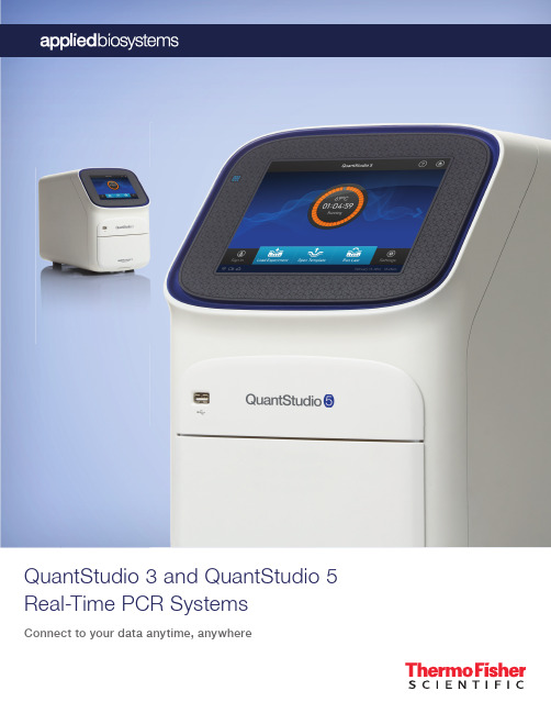
QuantStudio 3 and QuantStudio 5 Real-Time PCR SystemsConnect to your data anytime, anywhereConnect with your futureThe modern laboratory is undergoing a technological revolution. Today’s scientific breakthroughs emerge in a context of unparalleled connectivity. Lab instruments not only are more compact, automated, powerful, and accessible, but also can store and can connect to platforms that can share vast amounts of data, facilitating scientific advances through global collaboration.As your trusted partner at the leading edge of this era of innovation, we’ve developed the Applied Biosystems™QuantStudio™ 3 and 5 Real-Time PCR Systems. These high-performance benchtop instruments allow youto remotely monitor your runs, as well as easily access and securely share results with colleagues anywhere, anytime when connected to Thermo Fisher Cloud. With your data always within reach and shareable, the answers shaping the future of science are never far away.•Q uickly share data setsand protocols online.•S end large fi les securelyaround campus or aroundthe world.•I ntegrate and analyzemultiple data sets and datatypes into one project.•A ccess experimentruns from any location,anytime, with remotemonitoring.•W i-Fi enabled connectivity.•U tilize portable devices to quicklyanalyze data when you need to.†With Web access and Thermo Fisher Cloud.typequicklyneed to.mo Fisher Cloud.InteractivityCollaboration†Accessibility†• Interactive touch screen.•R un and edit directly from touch screen.•E asy and intuitive interface.The QuantStudio 3 and 5 Real-Time PCR Systems are the latest additions to our family of QuantStudio™systems. These instruments provide our latest advancements in touch screen usability, allowing you to stayconnected to your data easily. They’re designed for both new and experienced users who need simple andaffordable real-time PCR systems without compromising performance or quality.Discover the QuantStudio 3 and 5Real-Time PCR SystemsAccess, analyze, and share data anytime, anywhere —Remotely monitor your runs, analyze sophisticated data setsin minutes, store data in a secure space, and share resultsonline with colleagues across institutions and around theworld, with Web browser–based software.Obtain results you can trust — Detect diff erences in targetquantity as small as 1.5-fold in singleplex reactions, andobtain 10 logs of linear dynamic range.Establish standard operating procedures andcompliance with ease — Locked protocol templates,in-run quality control (QC) feedback, and QC traceability ofconsumables off er greater control of experiment data.Real-time data mark-up language (RDML) export is availablefor compatibility with MIQE guidelines.Helps save valuable time — 3 or 6 independenttemperature zones for fl exibility to run multiple experimentssimultaneously. Fast thermal cycling is also available, enablingresults in less than 30 minutes.Get started quickly — Instrument is factory-calibratedfor optical and thermal accuracy, quick installation, andimmediate use.Skip the learning curve — With preoptimized protocoltemplates, training is minimized for new users, allowing you tofocus on your research.Maximize benchtop space — Compact instrument canbe confi gured as stand-alone or with a computer to fi t mostlaboratory needs.Get a premium instrument at an aff ordable price —Innovation doesn’t have to come at a premium price.Get the state-of-the-art Applied Biosystems™ functionalityand industrial design that you’ve come to know, with theQuantStudio family of instruments.Figure 1. Graphical interface allows (A) easy editing of thermal cycling conditions and viewing of plate layout, as well as (B) viewing of amplifi cation plots anddrilling down to a subset of sample wells.• I nteractive touch-screen interface and simplifi ed QuantStudio ™Design and Analysis Software make it easy to get started and stay organized.• E asily identifi able icons guide you through the workfl ow to set up runs and analyze experiments.• G raphical interface allows easy editing of experimental conditions (Figure 1A).• I nteractive touch screen allows you to manipulate view to a particular graph or data point (Figure 1B).• O ption to pause a real-time PCR run on demand.• P reoptimized protocol templates allow quick selection of default protocols for standard applications.• L ocked workfl ow feature allows for experiment consistency in tightlycontrolled environments.InteractivitySimple, intuitive software — at your fi ngertipsWeb-based or online:• W eb browser–based system confi guration with PC or Mac ™computers.• S treamlined software for improved usability and analysisresponse time.• E nables secure access of your data when and where you want it.• N o software to install, no additional fees, and no versions to update.• Monitor and check instrument status.Desktop:• T raditional co-located computer system confi guration.• S treamlined software for improved usability and analysis response time.• N o additional fees.AccessibilityAccess QuantStudio Design and Analysis Software two waysFor more information about the Thermo Fisher Cloud platform and data security, go to thermofi /thermofishercloudAccess with Web browser–based software Co-locate with computer BACollaborationFast and powerful secondary analysis software to extract and share resultsFigure 3. Relative quantifi cation module for gene expression analysis. With this module, you can customize groupings of data within projects for a thorough comparison of data. The module also includes integrated correlation, volcano, and cluster plot analysis, with the ability to drill down to amplifi cation plots.Figure 2. Absolute quantifi cation module for gene expression analysis. The module enables analysis of genes of interest with the use of a standard curve. Additional fl exibility is achieved by importing standard curves from other experiments.Figure 4. Genotyping analysis module. This module expands on existing TaqMan ™Genotyper ™software with improved visuals and integrated traces of allelic discrimination plots. The module allows for thorough quality control of SNP assays to accurately refl ect true signals vs. background noise.Anywhere, anytime accessAccess your data with a compatible browser on any device. Each registered user has a PIN-protected account on Thermo Fisher Cloud.Fast and powerful analysisAnalysis speeds up to 10 times faster than our desktop software version, to help analyze more data and gain insights more quickly than before using Thermo Fisher Cloud.Easy to useOne-click quality checks and comparisons between diff erentvisualizations, for simple and convenient data analysis.Integrated analysis solutionIntegrate your experiments into a single project — analyze various groups of data, such as time course experiments or cell line comparisons, and pick ideal settings to easily compare data.Superior securityPowered by Amazon Web Services ™, the Thermo Fisher Cloud platform helps protect your data in a highly secure environment using 256-bit encryption and physical security measures.MIQE guideline supportThe instrument software allows users to save predefi ned analysis settings for auto-exporting run data into their format of choice, including RDML (real-time data mark-up language, compliant with MIQE guidelines) export format.Applied Biosystems ™Analysis Modules are innovative cloud-based data analysis applications that bring together multiple data sets in one convenient place, and render them in stunning data visualizations for enhanced analysis and insights.The Applied Biosystems Analysis Modules include:Absolute quantifi cationRelative quantifi cationGenotypingGenotyping analysisFigure 9. Allelic discrimination plot with traces using real-time PCR data. Cluster plot of 44 gDNA samples and 4 no-template controls (NTCs) genotyped using TaqMan ™SNP Genotyping Assay C_29086771_20, with both PCR and allelic discrimination performed on the QuantStudio 5 Real-Time PCR System. The novel use of real-time PCR data to plot SNP cluster progress aids in calling ambiguous samples and reduces run times by displaying the optimal number of cycles necessary for maximum cluster separation.For more information about TaqMan Assays and formats, go to thermofi /taqmanAssay fl exibility to support your applicationThe QuantStudio 3 and 5 systems support probe-based assays as well as intercalating dyes. TaqMan ™probe-based assays, developed with powerful algorithms and optimized master mixes, enable outstanding specifi city and sensitivity. SYBR ™Green chemistry is an economical alternative for target identifi cation or initial screening assays. The QuantStudio 3 system has 4 fi lters calibrated for FAM ™/SYBR Green, VIC ™/JOE ™, NED ™/TAMRA ™, and ROX ™dyes. The QuantStudio 5 System off ers 96-well and 384-well format options, allowing for a broader range of detection chemistries and assay multiplexing. The 96-well format has 6 excitation fi lters (450–680nm) and 6 emission fi lters (500–730nm), and the 384-well format has 5 excitation fi lters (450–650nm) and 5 emission fi lters (500–700nm).Figure 7. Melt curve analysis using the online version of the software. In this experiment, 96 replicates of human genomic DNA were amplifi ed using SYBR ™Select Master Mix with primers for RNASE P followed by a dissociation step. The reactions were run under Fast run conditions, showing C t uniformity with a mean of 25.7 (SD 0.077), and thermal uniformity as measured by the derivative peak with a melting temperature (T m ) of 84.17°C (SD 0.07°C).Figure 8. Multiplex reaction with 4 targets plus passive reference. Whole-plate amplifi cation plots of 96 replicates of cDNA made from universal human RNA (UHR) amplifi ed under Fast run conditions using TaqMan ™Multiplex Master Mix with MUSTANG PURPLE passive reference dye. Targets and labels: FZD1 labeled with FAM dye, APOE labeled with VIC dye, CD44 labeled with ABY ™dye, GAPDH labeled Melt curve analysis Multiplex gene expressionGenerate high-quality data for a variety of applicationsPerformance you can trustUtilizing proven OptiFlex ™technology and VeriFlex ™Blocks, QuantStudio 3 and 5 systems off er improved data accuracy and sensitivity for a broad range of genomic applications, such as analyses of gene expression, microRNAs and noncoding RNAs, SNP genotyping, copy number variation, mutation detection, drug metabolism enzymes, and protein expression.Precise quantifi cation with 1.5-fold discriminationFigure 5. The QuantStudio 3 and 5 systems provide sensitive detection and high-confi dence target discrimination down to 1.5-fold diff erences. (A) Amplifi cationplots for 1.5-fold dilutions of a KAZ plasmid amplifi ed with the PE2 TaqMan ™Assay under Fast run conditions using the TaqMan ™Fast Advanced Master Mix. Quantities assayed, and C t (SD): 1,000 copies, 27.9 (0.063); 1,500 copies, 27.4 (0.059); 3,000 copies, 26.4 (0.060); 4,500 copies, 25.8 (0.047); 6,667 copies, 25.2 (0.049); 10,000 copies, 24.5 (0.041). NTC = no-template control. (B) Standard curve generated from the C t values.BAExcellent reproducibility and 10-log dynamic range Figure 6. Real-time PCR reproducibility. This plot shows results from amplifi cation of KAZ target plasmid DNA in 10-fold dilutions using the 96-well block. The data show highly reproducible results over 10 logs of input template amount, illustrating thebroad linear dynamic range of the system.C TTechnical specifi cationsQuantStudio 3QuantStudio 5Sample capacity (wells)9696 or 384Reaction volume0.1mL block: 10–30 μL0.2mL block: 10–100 μL96-well:0.1 mL block: 10–30 μL 0.2 mL block: 10–100 μL 384-well: 5–20 μL Footprint (W x D x H)27 cm x 50 cm x 40 cm 27 cm x 50 cm x 40 cm Excitation source Bright white LED Bright white LEDOptical detection4 coupled fi lters96 wells: 6 decoupled fi lters 384 wells: 5 coupled fi ltersExcitation/detection range 450–600 nm/500–640 nm 96 wells: 450–680 nm/500–730 nm 384 wells: 450–650 nm/500–700 nm Multiplexing Up to 4 targets 96-well: up to 6 targets 384-well: up to 5 targets 2D barcode reading Optional OptionalHeating/cooling method PeltierPeltierTemperature zone function 3 VeriFlex zones 96 wells: 6 VeriFlex zones 384 wells: NA Max block ramp rate 6.5°C/sec 6.5°C/sec Average sample ramp rate 3.66°C/sec 3.66°C/secTemperature uniformity 0.4°C 0.4°C Temperature accuracy 0.25°C0.25°CRun time<30-minute runs<30-minute runsDye compatibility (name)FAM/SYBR Green, VIC/JOE/HEX/TET, ABY/NED/TAMRA/Cy ®3, JUN, ROX/Texas Red™FAM/SYBR Green, VIC/JOE/HEX/TET, ABY/NED/TAMRA/Cy3, JUN, ROX/Texas Red, MUSTANG PURPLE, Cy ®5/LIZ ™, Cy ®5.5Chemistry capabilities Fast/standard Fast/standardFeatures to assist with 21 CFR Part 11 compliance No Yes, with no additional fees Number of copies 1 copy1 copySensitivityDetect diff erences as small as 1.5-fold in target quantities in singleplex reactionDetect diff erences as small as 1.5-fold in target quantities in singleplex reactionSmartStart orientationEvery QuantStudio 3 andQuantStudio 5 system includes a SmartStart orientation to get you up and running quickly in your lab. The orientation includes basic qPCR familiarization and setup with both Thermo Fisher Cloud and online Instrument Management. QuantStudio 5 system owners receive a personalized qPCR application training.Online InstrumentManagementSign in to your account to access the award-winning† free online Instrument Management‡ tool that enables faster responses to requests for service or service quotes, plus fast connection to key instrument and service information.Comprehensiveinstrument warrantyOur factory-trained and certified field service engineers (FSEs) are focused on delivering the highest-quality workmanship. During the warranty period all qualifying repairs, including engineer time and travel, are covered.Flexible service plansChoose from a variety ofservice options that balanceyour budget, productivity, uptime, andregulatory requirements. Plans startwith the most basic repair models andscale to premium offerings includingadvanced support and complianceservices. On-site service plans areoptimal for labs that have time-sensitivework and need to get their instrumentback online quickly. These plansinclude guaranteed response timesin most regions, scheduled plannedmaintenance, and automatic softwareupdates. The AB Repair Center plan isa cost-effective choice for customerswho can allow their instrument tobe sent away for repair — this planprovides a loaner instrument so thatcustomers can maintain productivitywhile their instrument is being repaired.Compliance andvalidation servicesOur compliance and validationservices are designed to help youbalance business and regulatoryrequirements. From risk assessmentand hardware/software qualification tofull system validation, we partner withyou to help mitigate regulatory risks andget your processes up and running.Training coursesOur application and instrumenttraining programs are led byscientists who aim to enhance yourworkday through experimental designbest practices, workflow training, andinstrument troubleshooting. Hands-onclasses are available at our ThermoFisher Scientific training centers or inyour lab.Technical supportIf you have questions aboutproduct selection or use, assayor experiment design, data analysis, ortroubleshooting, contact our team oftechnical support scientists or accessour online product and applicationsupport tools.Financing optionsIf you’re looking for acceleratedreturn on investment,technology protection, or cash flowmanagement, our innovative financingoptions can help meet your company’sbudgetary needs and bottom-line goals.Contact your local sales representativefor more details.Service and support to help meet your changing needs†2012 Oracle™ Fusion Middleware Innovation Award.‡ O nline Instrument Management tool not available in all regions.Service plans at a glanceRepair Center service plans On-site service plansService plans at a glace AB Repair CenterSupport PlusAB Repair CenterSupport Plus CareAB MaintenancePlus AB Assurance AB Complete On-site response time Target 2 businessdays†Guaranteed 2business days†Guaranteed nextbusiness day†Scheduled on-site plannedmaintenance (PM)✓✓✓✓Remote diagnostics ✓✓✓✓✓Parts, labor, and travel forrepair, included✓✓10% discountoptional add-on inselected regions✓✓Computer repair andreplacement, included✓✓✓✓Priority access to Tech SupportMon–Fri, 8 a.m.–5 p.m. local time✓Priority access to RemoteService Engineer✓✓✓✓Requalification post-PM andcritical repairs✓Field Application Scientistconsultation✓Loaner instrument issued duringrepair (Repair Center plans only)✓✓†Response times vary by region. For a full schedule of courses, including self-paced online classes, go to /trainingFind out more at /quantstudio3-5For Research Use Only. Not for use in diagnostic procedures. © 2015 Thermo Fisher Scientific Inc. All rights reserved. All trademarks are the property of Thermo Fisher Scientific and its subsidiaries unless otherwise specified. TaqMan is a registered trademark of Roche Molecular Systems, Inc., used under permission and license. Mac is a trademark of Apple Inc. Amazon Web Services is a trademark of Amazon Technologies, Inc. Oracle is a trademark of Oracle International Corporation. CO016739 0815How to reach usTo find your order support or technical support team, go to /contactusFor product FAQs, protocols, training courses, and webinars, go to/technicalresourcesProductCat. No.Ordering information。

关于鼠标介绍的英文作文英文:Mouse is an essential part of our daily computer usage. It is a pointing device that helps us to navigate and interact with the graphical user interface of a computer. A typical mouse has two buttons, a scroll wheel, and a cursor. The primary button is used to select or click on an item, while the secondary button is used for context menus and other functions. The scroll wheel allows us to scroll upand down a page or document, making it easier to read and navigate. The cursor is the arrow on the screen that moves as we move the mouse.One of the most significant advantages of using a mouse is its precision. It enables us to click on small icons and buttons accurately, which can be difficult to do with a touchpad or trackball. Moreover, using a mouse can help to reduce the strain on our hands and wrists, as we don't have to move our fingers as much as we would with a touchpad.Another advantage of the mouse is its versatility. It can be used for a wide range of tasks, from playing games to editing documents. For example, when playing a game, we can use the mouse to aim and shoot, while in a document editor, we can use it to highlight text and make changes.Overall, the mouse is an indispensable tool for computer users, and its benefits cannot be overstated.中文:鼠标是我们日常使用电脑的必要部件。
sip_digital_design_dsDATASHEETCADENCE SIPDIGITAL CO-DESIGN TECHNOLOGYManufacturers of high-performancec onsumer electronics are turning to SiP design because it can provide a number of significant advantages such as increased functional density, integration of disparate chip technologies, low power, improved signal performance/integrity and ease of integration into PCB system. However, this also means it requires expert engineering talent in widely divergent fields, which, to date, has limited mainstream adoption. By streamlining the integration of multiple high-pin-count chips onto a single substrate through a concurrent connectivity driven co-design methodology, the Cadence SiP digital co-design technology allowsc ompanies to adopt what were once expert engineering SiP design capabilities for mainstream product development.Cadence SiP solutions seamlessly integrate into Cadence Encounter ? technology for die abstract co-design, Cadence Virtuoso ? technology for RF m odule design, and Cadence Allegro ? technology for package/board co-design. (See Figure 1.)A COMPLETECONNECTIVITY DRIVEN CO-DESIGN SOLUTIONThe Cadence digital-driven SiP flow focuses on the design challenges of integrating multiple large high-pin-count chips onto a single substrate. This flow targets the major challenges of SiP level connectivity definition and management, physical concept prototyping of the SiP floorplan, including multi-chip die stacks, and die I/O planning to optimize and minimize substrate connectivity routing and signal integrity challenges. This flow is driven by Encounter and Verilog ? connectivity. CADENCE SiP DIGITAL DESIGNSystem-in-package (SiP) implementation poses new hurdles for system architects and designers. Conventional EDA solutions have failed to automate the design processes required for efficient SiP development. By enabling and integrating design concept exploration, capture, construction, optimization, and validation of complex multi-chip and discrete substrate assemblies on printed circuit boards (PCBs), the Cadence SiP design technology streamlines the integration of multiple high-pin-count chips onto a single substrate.Cadence technology for digital SiP design includes three focused products for full SiP implementation:Cadence SiP Digital Architect for front-end design concept definition and evaluation Cadence SiP Digital SI for detailed interconnect extraction, modeling and signal integrity/power delivery analysis ? Cadence SiP Digital Layout for constraint and rules driven detailed physical substrate construction and manufacturing preparationCADENCE SiP DIGITAL ARCHITECTCadence SiP Digital Architect provides a SiP concept prototyping environment for early design exploration, evaluation and tradeoff using a connectivity authoring and driven co-design methodology across die abstract, package substrate and PCB system. Built around a unique System Connectivity Manager, SiP DigitalArchitect provides the architect with a unique e nvironment to explore and define system connectivity/functionality that is optimized between ICs, SiP packages ubstrate, and target PCB system through concurrent co-design. It allows engineersto perform rapid “what-if” feasibility studies to ensure maximum devicef unctional density performance, while minimizing power consumption. It fully supports IC-driven or package/board substrate-driven flows with cross-fabric domain engineering change orders (ECO) and layout versus schematic (LVS)v alidation. Since its design focus isp redominantly digitally based, analog and/or RF mixed-signal design content is imported and managed as a hierarchical sub-block(s).BENEFITSAllows rapid “what-if” feasibilitystudies for maximum device functional density, performance, and minimal power consumption ? Enables rapid system-level connectivity capture with ability to bind into alterna-tive physical implementation scenarios to evaluate performance and tradeoffs ? Provides IC I/O padring/array co-design and optimization at the IC, substrate, and system levelsFigure 1: Cadence SiP Digital Co-Design TechnologyCADENCE SiP DIGITAL LAYOUTBENEFITSProvides 3D die stack creation/editing for rapid stack assembly and optimizationEnables IC I/O pad ring/array co-design and connectivity optimization at the IC, substrate, and system levelsAllows connectivity assignment and optimization between ICs and sub-strate for optimized/minimal layer usage based on signal integrity and routabilityReduces tedious, time-consuming, and manual breakout editing via flip-chip die autoroute-breakout Constraint-driven HDI design with automation-assisted interactive routing speeds implementation and reduces potential errors.Includes comprehensive substrate DFM capabilities for rapid designm anufacturing preparationProvides 3D design viewer and DRC for accurate full 3D wire bondshell verification, design review debug,and design documentation for assembly and testTeam-based design partitioning reduces design cycle time and optimizes designer resourcesCadence SiP Digital Layout provides ac onstraint- and rules-driven layoute nvironment for SiP design. This includessubstrate place and route, final connectivityoptimization at the IC, substrate, andsystem levels, manufacturing preparation,full design validation, and tapeout. Theenvironment features integrated IC/pack-age I/O planning capabilities and threedimensional (3D) die stack creation andediting capabilities. In addition, full onlinedesign-rule checking (DRC) supports thecomplex and unique requirements of allcombinations of laminate, ceramic, anddeposited substrate technologies. Multi-layer flip-chip along with radial any-anglerouting substrate routing provide rapidconstraint-driven interconnect creation. CADENCE SiP DIGITAL SICadence SiP Digital SI provides ane nvironment for the co-simulation of SiP interconnect, including embedded ICs and the target PCB. By using its embedded integration with a third-party supplied 3D field solver engine combined with a SPICE-based signal integrity simulation environment, engineers can make tradeoffs to minimize cost while maximizing performance of the package module interconnect. To model and simulate complex 3D SiP structures, SiP Digital SI integrated S-Parameter support, and fast, h igh-capacity simulation (10,000 bits in seconds) to provide a uniquec ombination of fast and accurate multi-gigahertz i nterconnect analysis.BENEFITSProvides a highly integrated physical and electrical design and simulation environmentPre-post route interconnect analysis with graphical topology exploration enables rapid what-if performance tuningIncludes a SPICE-based simulation engine and embedded integration with a third-party supplied 3D field solverEnables rapid evaluation of cost versus performance tradeoffs through its virtual prototyping environmentReads/writes Cadence Digital SiP Layout filesEnsures sufficient and efficient power delivery network (PDN) designFigure 3: Virtual System Interconnect ModelsI/O PLANNERThe IC die abstract I/O planner provides the definition and optimization of co-design die bump matrix, I/O pad ring/array through connectivity assignment, I/O placement, and redistribution layer (RDL) routing. It can create either a die abstract from scratch, or load an abstract from the digital IC design team (LEF/DEF or OA), and then optimize it in the context of the SiP substrate as well as other IC die in the design. The I/O planner is based on Encounter technology, ensuring it is 100 percent compatible with the chip design team’s IC tools and provides complete IC technology file compliance. (See Figure 4.) Figure 4: I/O PlannerSUBSTRATE FLOORPLANNERThe floorplanner allows the physicalp rototyping and evaluation of variouss ubstrate-level SiP implementationc oncepts. It provides a full rules-driven, connectivity-based capability that ensures a correct-by-construction approach. The die abstracts, discrete components, and connectivity and constraint data is usedto build the physical SiP implementation. The SiP architect can then use the graphical, intuitive editing tools to construct and evaluate critical sections of the design. (See Figure 5.)Figure 5: Substrate Floorplanner3D DIE STACK EDITORThe die stack editor provides a 3Dc onstruction environment for assembling complex die stacks which can include spacers, interposers and die attachm ethods such as wirebond and flip chip. (See Figure 6.)Figure 6: 3D Die Stack Editor3D DESIGN VIEWERThe Cadence 3D Design Viewer is a full, solid model 3D viewer and 3D wirebond DRC solution for complex IC package designs. It allows users to visualize and investigate an entire design, or a selected design subset, such as a die stack orc omplex via array. It also provides ac ommon reference point for cross-team design reviews. (See Figure 7.)KEY FEATURES**Reference the product capabilities grid at the end of this datasheet to see what features are applicable to what product. SYSTEM CONNECTIVITY MANAGERThe System Connectivity Manager is the “cockpit” or “dashboard” of the SiP Digital Architect. It allows the project architect to rapidly author and/or capture the connectivity of the SiP , which includes importing IC die Verilog netlists for chips that comprise the SiP design and interfac-ing to the PCB footprint symbol of the completed SiP . Embedded LVS routines and ECO management capabilities ensure that the logical SiP definition matches the physical SiP implementation, including any ICs that are partitioned and co-designed as part of the SiP . (See Figure 2.)Figure 2: System Connectivity ManagerVIRTUAL SYSTEM INTERCONNECT (VSIC) MODELSAn integrated graphical and topological interconnect modeling and simulation capability provides the ability to create and explore the signal integrity (SI)p erformance of proposed system-levelc onnectivity. Embedded simulation capability provides time and frequency domain interconnect simulation, including industry-standard S-Parameter models. The embedded integration with a third-party supplied full 3D quasi-static field solver further provides the extraction and creation of detailed, accurate geometric IBIS, RLGC or S-Parameter models of complex 3D interconnect structures. (See Figure 3.)Figure 7: 3D Design Viewer INTEGRATED CONSTRAINT MANAGEMENTThe spreadsheet based Integratedc onstraint management system provides the definition, application, and manage-ment of interconnect constraints and topologies at the physical prototyping and implementation level. Designers can import constraints and apply them to industry-standard buss protocols—such as PCI-Express and DDR2—through hier-archical interconnect topology templates that are available from Cadence as well as various IC vendors. (See Figure 8.) EMBEDDED INTEGRATION WITH A THIRD-PARTY 3D FIELD SOLVER Seamless integration with a third-party supplied quasi-static field solver engine combined with SPICE-based simulation engines all accessed directly from within the physical SiP design environment enable modeling and simulation of pack-age interconnect, without the time-con-suming setup of stand-alone point tools. Engineers can quickly check tradeoffs to the physical design to ensure that electri-cal requirements are not compromised. Integration of analysis and design technol-ogy also allows analysis tasks that were formerly done by package SI experts to be shared by a broader group within the SiP design community. (See Figure 9.) PACKAGE MODELING FOR SYSTEM LEVEL ANALYSISCreation of IBIS, RLC, or Cadence DML interconnect models is easily accomplished, either for a selected set of nets or for the entire package. Design teams can then easily re-use these models at the systemlevel to ensure that package effects areproperly considered when optimizingPCB cost/performance tradeoffs.POWER DELIVERY NETWORKDESIGN FOR LOW POWERAn integrated analysis environmentenables sufficient, efficient, and stablepower delivery network design throughthe optimization of the package imped-ance profile and minimized powersupply voltage ripple.INTEGRATION WITH CHIP-LEVELIR DROP ANALYSISCreation of package power and groundRLC models that can be automaticallyconsumed by IC core IR drop analysis(static and dynamic) using CadenceVoltageStorm?. (See Figure 10.)SUBSTRATE EDITORThe substrate place and route editorallows the package layout designer tophysically implement a SiP design basedon the final chosen concept, including alllevels of manufacturing preparation priorto mask creation. It provides a full rules-driven, connectivity-based capability that ensures a correct-by-construction approach backed by a comprehensive design and assembly rule checking environment. The die abstracts, discrete components, and connectivity and constraint data are usedto build the physical SiP implementation. The package layout designer can thenuse intuitive graphical editing tools to implement the design and prepare it formanufacture. It also supports all packagingFigure 8: Integrated Constraint ManagementFigure 10: Integration with VoltageStorm for chip-level IR drop analysis including the package Figure 9: Embedded signal integrity simulationtechnologyFigure 12: Comprehensive ARC checking environmentFigure 13: Auto/Interactive wirebonding using Kulicke & Soffa verified wire profilesFigure 11: Substrate Editormethods: PGA, LGA, BGA, micro-BGA, and chip scale, as well as flip-chip and wirebond attach methods. An embedded, push-button, full 3D quasi-static fieldsolver provides the extraction and creation of detailed, accurate geometric RLC or S-Parameter package simulation models for use during PCB design. (See Figure 11.)ASSEMBLY RULE CHECKING (ARC)A comprehensive assembly and manufac-turing rule checker provides over 50 SiP specific checks. Check can be executed as a check-group, or individually, or as a custom selection. Check results appear in the Constraint Manager DRC tab and as graphical markers in the design. (See Figure 12.)AUTO/INTERACTIVE WIREBONDINGNew, highly productive environment pro-vides fast, powerful and flexible bondshell creation and editing. Constraint/rules driven automatic bondfinger arrayp lacement can be used with staggered die pads, multiple bond levels, multiple bond rings, and both symmetrical and non-symmetrical designs. For fast initial what-if prototyping of single or multiple die stacks the “autobond” featureinstantly creates a symmetrical bondshell pattern including power and ground rings. Unique push and shove bondfinger edit-ing enables extremely complex bondshells to be developed in minutes, delivering unparalleled capability and productivity. True wireprofile support enables DFM-driven design using manufacturing verified wire loop data. An included Kulicke & Soffa verified loop profile library ensures that any wirebond patterns designed meet manufacturing signoff. Wirebond attached die flags and power/ground rings can be quickly created, edited, and optimized for multiple voltage supplies. (See Figure 13.)PRODUCT FEATURESSiP DIGITAL ARCHITECT GXL SiP DIGITALARCHITECTXLSiP DIGITALLAYOUTGXLSiPDIGITALSI XLSiP RFARCHITECTXLSiP RFLAYOUTGXLDie/BGA footprint compare using DEF/OA/.TXTFilled shapes (metal) creation and editingDesign documentation (dimensioning, annotation)??Assembly Rule Checking (ARC) system??Etch back of plating traces??Plating bar generation??Manufacturing/documentation export/import capabilities (stream, dxf, AIF)??Substrate mask output (Gerber, GDSII)??Full design-status reporting capabilitiesWaived DRCs (creation and reporting)Degassing of filled metal shapes??Thieving (metal area balancing)??2008 Cadence Design Systems, Inc. All rights reserved. Cadence, Allegro, Encounter, SourceLink, Verilog, Virtuoso, and VoltageStorm are registered For more information, contact Cadence sales at:1.800.746.6223or log on to:/doc/b20338efaeaad1f346933fd4.html / cadence/contact_usSPECIFICATIONSSYSTEM REQUIREMENTSOpenGL graphics compliance with a minimum 64MB of dedicated graphics memoryPLATFORM/OSWindows XP , Vista Enterprise Solaris LinuxINTERFACESLEF/DEF 5.1 to 5.7 OA 2.2 VerilogTHIRD-PARTY SUPPORTApache-DA embedded PakSI-E 3D field solver engineCADENCE SERVICES AND SUPPORTCadence application engineers can answer your technical questions by telephone, email, or Internet—they can also provide technical assistance and custom training ? Cadence certified instructors teach more than 70 courses and bring their real-world experience into the classroom ? More than 25 Internet Learning Series (iLS) online courses allow you thefl exibility of training at your own c omputer via the Internet ? SourceLink ? online customer support gives you answers to your technical questions—24 hours a day, 7 days a week—including the latest in quarterly software rollups, product change release information, technicald ocumentation, solutions, software updates, and more。
介绍鼠标原理的英语作文Title: Understanding the Principles Behind the Mouse: An Insight into Its Functionality。
The mouse, a quintessential input device for modern computing, plays a pivotal role in navigating graphical user interfaces (GUIs) and interacting with digital environments. Its functionality relies on a complex interplay of hardware and software components, all geared towards translating physical movements into digital commands. In this essay, we delve into the principles underlying the operation of a mouse.1. Introduction to the Mouse:The mouse is a pointing device that typically consists of two main components: a housing containing internal circuitry and sensors, and a surface underneath outfitted with a tracking mechanism, usually a ball or an optical sensor.2. Tracking Mechanism:The tracking mechanism is responsible for detecting the mouse's movement across a surface and translating itinto digital signals that can be interpreted by the computer. Early mice utilized a rubber ball that rolled along surfaces, with internal rollers sensing the direction and speed of movement. However, modern mice predominantly employ optical sensors, which use light-emitting diodes (LEDs) and photodiodes to track movement optically. As the mouse moves, the sensor captures successive images of the surface, enabling precise tracking of its position.3. Communication Interface:Once movement is detected, the mouse communicatesthis information to the computer through various interfaces. Most commonly, mice use either USB (Universal Serial Bus)or wireless protocols such as Bluetooth to transmit data to the computer. These interfaces ensure seamless integration with the computer system, allowing for real-timeinteraction with graphical elements on the screen.4. Sensor Technologies:Optical mice rely on imaging sensors to capture surface details and track movement accurately. These sensors capture images of the surface beneath the mouse at high speed and analyze the differences between successive frames to determine the direction and distance of movement. Advanced optical sensors employ techniques such as image correlation and motion estimation algorithms to enhance accuracy and responsiveness.5. Resolution and Sensitivity:The resolution of a mouse refers to the precision with which it can detect movement. It is typically measured in dots per inch (DPI), with higher DPI values corresponding to greater sensitivity and finer control. Adjustable DPI settings allow users to customize themouse's responsiveness to suit their preferences and the task at hand, whether it be precise graphic design work orrapid gaming movements.6. Ergonomics and Design:Beyond its technical specifications, the design of a mouse also plays a crucial role in its usability and comfort. Ergonomic considerations such as grip style, button placement, and overall shape influence the user's experience and can mitigate the risk of repetitive strain injuries associated with prolonged mouse usage. Manufacturers often conduct extensive research and user testing to optimize the design for comfort and efficiency.7. Integration with Operating Systems:Operating systems play a vital role in interpreting mouse input and translating it into meaningful actions within software applications. Through device drivers and system-level software, the operating system facilitates communication between the mouse and various applications, enabling functionalities such as cursor movement, button clicks, and gesture recognition.8. Conclusion:In conclusion, the mouse stands as a testament to the ingenuity of human-computer interaction design, bridging the physical and digital realms with remarkable precision and fluidity. Its underlying principles encompass a fusion of hardware engineering, sensor technologies, ergonomic design, and software integration, all working in harmony to empower users in their digital endeavors. As computing technologies continue to evolve, so too will the mouse, adapting to meet the ever-changing needs and expectations of users in an increasingly interconnected world.。
This is a guide to downloading and logging into Adobe Creative Cloud with your Winthrop account. Adobe Creative Cloud (Adobe CC) includes multiple types of cloud based software that you can use to edit images, documents, videos, sound, and more.1.First, navigate to/You will need to click on “SignIn” in the upper right corner, evenif you do not have an account yet.2.You will be brought to the Sign Inscreen.You will need to type in yourWinthrop username, including the@ to sign in.It may ask you to select “PersonalAccount” or “Company or SchoolAccount”. Select “Company orSchool Account”.3.You will now be brought to aWinthrop login page, type in yourWinthrop username and password,*****************************and click “Sign In”.**Please note that if you are having difficulty getting access to Adobe Creative Cloud, you will need to contact your professor. You r professor may need to request that IT assigns an Adobe license to your account. The ITC does not have the ability to get you logged into AdobeCreative Cloud.**4.You will be brought to this screen:Click “Open” under the middlewhere it says “Your Services:Creative Cloud”5.You will be brought to this screen:You can download the desktopapp for each Adobe CreativeCloud app that you would like touse by clicking on the softwareicon and then “Get Desktop App”.If you click on “All your Apps”you will be shown all of the appsavailable to you through AdobeCreative Cloud. You can alsoclick on the tab titled “Apps” atthe top of the screen.6.Another alternative way to getto download the apps is afteryou’ve clicked either the“Apps” tab at the top of thescreen or “All your Apps”circled in Step 5. You canclick the “Download” button onany of the apps you’d like todownload and utilize, and youcan also click the smallmortarboard to get additionalinformation on each app.7.If you would like tutorials onhow to use the apps, scrolldown while on the screen inStep 5. You will see a spot atthe bottom of the webpage thatwill give you access to varioustutorials Adobe has created fortheir apps. Alternatively, at thetop of the page is a tab titled“Learn” which will also bringyou to the tutorials.8.If you’ve chosen to save yourwork to the cloud rather thanon your desktop (which couldbe useful if you swapcomputers or have multiplecomputers!), to see your workyou will need to click on thetab at the top of your page“Your work”.9.Adobe also offers several resources if you click onthe Apps tab, or in the 9 dot menu on the upper rightcorner as pictured. Here is a brief description ofeach of these resources.a.Creative Cloud- This takes you back toyour Adobe Creative Cloud homepage.b.Document Cloud- This allows you to store,share, and view PDFs on the go.c.Experience Cloud- This platform givesorganizations/businesses everything theyneed to deliver personalized marketing andexperiences to customers. It is a collectionof Adobe’s integrated online marketing andweb analytics products.d.Spark- This is an online and mobile designapp that allows non-designers to createprofessional quality graphics, short videos,and single page web ‘stories’.e.Lightroom- Lightroom is an app thatcomplements Photoshop, and there is amore in-depth description further below,where all of the app descriptions are.f.Portfolio- This is optimized for showcasing your creative work. You can choosemultiple layouts designed to fit any creative field.g.Behance- This is a social media platform that is owned by Adobe. It is used to allowindividuals who are graphic artists and designers to showcase their portfolio of visualwork.h.Stock - This gives you access to the Adobe library of stock 'assets’. This includes stockphotos, vector images, 3D images, templates, and more.i.Fonts - This lets you browse and download fonts from Adobe’s font library. You cansearch by type of font (serif, sans serif, script, etc) as well.j.Tutorials - This takes you to Adobe’s tutorials area for each of their programs.k.Support Community- This allows you to go onto Adobe’s support forums to ask questions or search for information.These are the apps that you will have access to and a brief description of each: PhotoshopAdobe Photoshop is an image editing and manipulation software. Photoshop is great atworking with raster (also sometimes called bitmap) graphics (like photographs) and iscapable of producing detailed compositions. While originally intended to be a photomanipulation program, Photoshop is also commonly used by digital painters and designprofessionals and students.IllustratorAdobe Illustrator is similar to Photoshop in that you can create and edit graphics. Thereare some major differences though. Adobe Illustrator uses lines, curves, and geometricdata and creates vector images whereas Photoshop uses and creates raster images whichare composed of individual pixels. Vector images have less detail than raster images, butthey can be resized infinitely without any quality loss - this can be beneficial for printed graphics and web design. Vector images are sometimes called resolution-independent graphics.Acrobat DCAdobe Acrobat DC allows you to view, edit, manage, print and even sign PDFs onlineand offline.InDesignAdobe InDesign is for creating page layouts and publishing. It has more options andcontrol with typography than other programs such as Photoshop, but less options when itcomes to graphics. InDesign is a great option for editing and creating multi pagedocuments, magazines, and more.XDAdobe XD is a program that allows you to design, prototype, and share user experiencedesign (also known as UX) and user interface design (also known as UI). This is a vectorbased design tool for things like web pages and phone apps.Premier ProAdobe Premiere Pro is used to edit and cut video tracks, and then export them in the desired format. The project panel allows you to grab individual clips and add them to a timeline to create a movie. Titles can be added, elements from the rest of the Adobe suite can be added, and color corrections can be appliedPremier RushAdobe Premier Rush is an all-in-one video editing solution that allows content producers to quickly edit a video and publish it on platforms like YouTube and other social networks. It is in many ways, a Premier Pro “Lite” version.FrescoAdobe Fresco is an illustration app. It includes many familiar brushes from Photoshop with the precision of vector brushes and something new, called “Live Brushes”. Live Brushes allow digital artists to paint with watercolors and oils that act like the real thing, except no messy clean up!After EffectsAdobe After Effects is used for adding visual effects to videos or animations. After Effects can also be used to create animations of both text and complex characters. After Effects can also do other things like adding clips into a clip or overlaying green-screens. It is very hardware intensive, so be sure to have at least 8GB of RAM and plenty of CPU power available if you want to use it.BridgeAdobe Bridge is basically an organizer for photos and designs within the Adobe Creative Suite. Bridge is used for batch file utility functions, such as renaming files or editing other metadata on the raw camera IPTC and XMP level. Bridge isn’t necessarily a program used for creating or making visual edits to actual content. Rather, think of it as a handy assistant for all other Adobe software.Lightroom ClassicAdobe Lightroom Classic is a similar program to Adobe Photoshop, but there are somelarge differences. Lightroom Classic is a desktop based program rather than cloudbased. It was created as a complement to Photoshop, and has some cool organizingabilities and ways to create albums. There are no brushes or pen tools in LightroomClassic- you cannot create graphics from scratch like you can in Photoshop orIllustrator. Lightroom Classic can also convert RAW image types and manipulate them. RAW images are also known as ‘digital negatives’. RAW files carry more information and usually are larger than other file types such as a JPG - basically when shooting in RAW, you are getting everything that the image sensor in the camera has picked up with no digital manipulation. Lightroom offers ease of use when you need to process multiple files efficiently. It also offers ‘non-destructive editing’ which keeps the original file intact - so no accidentally saving over the original!LightroomOkay, I know it is confusing - what is Lightroom and why is there Lightroom Classictoo? Adobe Lightroom is very similar to Lightroom Classic - the biggest differencebeing that Lightroom is cloud based whereas Lightroom Classic is desktop based.Some other differences include the ability to have automatic file backup and automatictagging and what Adobe calls ‘intelligent search’ - Lightroom Classic offers only a manual search and no automatic tagging.DimensionAdobe Dimensions is a 3D rendering and design software. It is really great for creating3D mockups for products or presentations. The software provides 3D models,materials, environments and lighting so you do not have to create everything fromscratch if you don’t want to do that.DreamweaverAdobe Dreamweaver is kind of like a graphical version of Notepad++ (a code editorthat supports several different languages). It highlights syntax and shows you a roughpreview of what your code will look like at the same time. Many of its toolsautomatically generate the necessary code when using the visual side of the program.Some of the languages that Dreamweaver is compatible with: ActionScript, ASP, C#, CSS, ColdFusion, EDML, XHTML, XML, XSLT, HTML, Java, JavaScript, PHP, VB, VBScript, and WML.AnimateAdobe Animate is a multimedia authoring and computer animation program. You candesign interactive animations and create cartoons, advertisements, games, and more.Many people may recall Adobe Flash - this is sort of like a replacement for Flash fromAdobe.Character AnimatorAdobe Character Animator brings your Photoshop and/or Illustrator creations to life. Itcombines live motion-capture with a multi-track recording system to control layered2D puppets. You do so by first capturing your performance using a camera,microphone, keyboard, mouse, or touch screen. While you are performing, the programcaptures your facial expressions. So you can become your character in a way!AuditionAdobe Audition is very useful for editing audio. It can be used to edit and mix soundsor fine-tune and re-master soundtracks.Media EncoderAdobe Media Encoder lets you save media for almost any screen or device. It supportsmultiple formats and media can be saved in multiple outputs for optimal playback on avariety of resolutions and devices. Cue points can be added to playback to triggerpresentation specific actions. Video can also be resized or cropped within MediaEncoder. Metadata editing is supported in the most recent version and will pass information to the rest of the Adobe suite.InCopyAdobe InCopy is a professional word processor that integrates with InDesign. WhileInDesign is used to publish materials, InCopy is used by editors to write, edit, trackchanges, and do very basic design to documents.PreludeAdobe Prelude is a video tool, but it isn’t for editing; it is for screening video clips andorganizing them. Prelude can log videos, tag, transcode, and search through footagequickly.Fuse CC (Beta)Adobe Fuse CC is a 3D computer graphics software that enables users to create 3Dhuman characters. Its main novelty is the ability to import and integrate user generatedcontent into the character creator. There are also multiple presets that you can use tocreate your character or model.Muse CCAdobe Muse is a discontinued offline website builder used to create fixed, fluid, oradaptive websites, without the need to write code. It generates static pages, but does notmanage hosting. Adobe does offer Dreamweaver as another website builder, but thedifference is that you need programming knowledge and web design skills to useDreamweaver, while Muse implies the awareness of design basics only. You can still use Muse CC, but Adobe no longer offers updates or support for the program.。
GrIPD: A Graphical Interface Editing Tool and Run-timeEnvironment for Pure DataJoseph A. SarloDepartment of Music, University of California, San Diegoemail: jsarlo@AbstractWe describe here a new interface tool for Pure Data (Pd). GrIPD (Graphical Interface for Pure Data) is a cross-platform software package that allows one to design custom graphical user interfaces for Pd patches. GrIPD is not a replacement for the native Pd interface, but rather, is intended to allow one to create a “performance-time” front end for a Pd patch. GrIPD extends the usability of Pd through various features including a multi-process design structure and TCP/IP network communication system that natively allow for various multiple-computer implementations.1 IntroductionIn the realm of real-time computer interaction, knowledge of the current state of the system is crucial. This is especially the case for real-time interactive computer music performances, in which the cost of system interpretation error is high. Indeed, the very concept of interactivity necessitates some degree of system awareness. Frequently in computer music performances, this awareness is derived from auditory cues, as the performer responds to the sound generated by the system. However, visual information is often equally important. The user must also be able to alter the state of the system. As Norman defines (1986), there is a Gulf of Evaluation and a Gulf of Execution between the user and the system that must be bridged. It is the role of the user interface to bridge these gaps.Many real-time computer music systems exist. One such system is Pure Data (Pd) (Puckette 1996). Essentially, a real-time system is implemented in Pd by defining a set of interconnected objects, the graph of which is referred to as a patch. The same interface is used for both designing the system and interacting with it.GrIPD (Graphical Interface for Pure Data) has been developed as a “performance-time” user interface system for Pd. GrIPD is not intended as a replacement for the native Pd interface, which is used at “design-time” for constructing Pd patches. Instead, the purpose of GrIPD is to allow for the creation and usage of custom “performance-time” graphical user interfaces (GUIs) for individual Pd patches. Like Pd itself, GrIPD is both cross-platform and open-source. GrIPD is currently known to run on x86 Linux/GTK+ systems and all Microsoft Windows operating systems from Windows 95 to Windows XP.In this paper we will discuss the architecture and design of GrIPD, its usage and noteworthy features, and plans for future improvements.2 Architecture and DesignThe GrIPD software package consists of two main components: the GrIPD Pd object and the GUI editor and run-time environment application. These two components operate as completely separate processes and communicate via TCP/IP. Messages are passed between the Pd object and the GUI application using a simple ASCII protocol.2.1 The GrIPD Pd ObjectThe GrIPD Pd object is essentially an external library that is instantiated inside a Pd patch. The object itself is written in the C programming language. It has three main functions. Firstly, it acts as the TCP/IP server for the GrIPD communication system, for which the GUI editor and run-time environment application is the client. Also, it includes the internal messaging system that allows a patch to seamlessly communicate with the GrIPD system without having to explicitly patch to the GrIPD Pd object. Lastly, the Pd object has functions to control aspects of the GUI application such as opening, closing, and locking.The TCP/IP server aspect of the GrIPD Pd object functions in much the same way that most servers do. It opens a socket using an available port number or a port number specified explicitly as an argument to the object at instantiation time. The port is polled until a connection is accepted from the client GUI application. The GrIPD Pd object has an outlet to report the current connection status. After the connection is established, the socket is continually polled for incoming messages from the client. Similarly, messages that are to be sent from the server to the client are queued into a buffer thatis periodically sent and flushed. The polling interval for both sending and receiving are user adjustable.A Pd patch communicates with the GrIPD system through the Pd messaging system of “send” and “receive” objects. This is similar to the way the native Pd GUI objects function, and thus, the GrIPD system can easily be incorporated into existing Pd patches. When the GrIPD Pd object receives a message reporting the value of a control (e.g. slider, button, etc.) from the GUI client application, the GrIPD Pd object sends that value to the appropriate “receive” objects of the Pd patch. Similarly, the GrIPD Pd object contains multiple “receive” objects corresponding to the GUI controls of the client GUI application. The GrIPD Pd object can thus listen for appropriate messages from the “send” objects of the Pd patch and relay them to the GUI client application controls.The GrIPD Pd object also has functions to control various aspects of the GUI application itself. For this, the GrIPD Pd object has one inlet that accepts the following messages:•connect: begin polling the socket for an incoming TCP/IP connection•disconnect: close the TCP/IP connection•open<optional filename>: launch the GrIPD GUI client and optionally open a GrIPD GUIdefinition file•open_locked<optional filename>: launch the GrIPD GUI client in locked mode,disallowing any editing of the GUI, andoptionally open a GrIPD GUI definition file •lock: place the GrIPD GUI application in locked mode, disallowing any editing of theGUI•unlock: place the GrIPD GUI application in unlocked (default) mode, allowing editing ofthe GUI•hide: hide the window of the GrIPD GUI application, but do not close or disconnect fromthe TCP/IP connection•show: show the window of the GrIPD GUI application that has been hidden, either by theGrIPD Pd object or the GrIPD GUI applicationitself•poll_send<integer polling interval>: set the polling interval for sending and flushing theoutgoing message queue•poll_receive<integer polling interval>: set the polling interval for receiving messages •set_path<filepath>: set the path to the location of the GrIPD GUI application (for usewith open) 2.2 The GrIPD Editor and Run-time EnvironmentThe GrIPD editor and run-time environment is a stand-alone application. It is in this application that the GUI for a Pd patch using the GrIPD system is both edited and used. It communicates with Pd through the GrIPD Pd object by acting as the TCP/IP client of the GrIPD communication system. Like Pd itself, it has two main modes of operation: edit mode and performance mode.In edit mode, a GUI for a Pd patch can designed and edited. This is done by creating GUI controls (e.g. sliders, buttons, etc.) and editing there properties as desired. The GrIPD GUI application implements a WYSIWYG (what-you-see-is-what-you-get) style of editing. When a control is created, it appears on the GUI application window and can be moved and resized by the usual WYSIWYG means of mouse dragging. Other properties, such as color and font, can be edited through a properties sub-window. Several global properties can also be set, including window title, background color, and polling intervals.While in performance mode, the GUI controls provide their normal control functions. When acted upon, they report their status to the GrIPD Pd object via the TCP/IP communication system. For example, when a button is pressed, it reports both a “bang” message and its send symbol name to the GrIPD Pd object, which then sends a ”bang” to all “receive” objects in the Pd patch sharing that symbol name. Controls can also receive messages from the GrIPD Pd object to change their status by the reverse process. In addition to the status of the GUI controls, the GrIPD GUI application can also send keyboard, mouse, and joystick events to the GrIPD Pd object.The GUI application itself was written using the Python programming language (Van Rossum and Drake 2002) and the wxWindows GUI library (Smart, et al. 2003) via the wxPython binding library. These tools offer several advantages. Firstly, both the Python language itself and the wxWindows library are cross platform. This allows the GUI application to be supported by multiple platforms without the need for multiple versions of source code. Secondly, the wxWindows GUI library takes advantage of native GUI controls of the various platforms it runs under. It accomplishes this by simply implementing its GUI components as wrappers around the system’s native GUI components. This has several advantages discussed below.3 Features and UsageThe GrIPD system has several features that provide extended function and configuration to Pd. The most noteworthy of these are due to two main aspects of the GrIPD system: the graphical and control functions of theGUI application and the multi-process design architecture.GrIPD extends the interface possibilities of Pd by offering GUI controls not available in Pd itself. These include multi-size, color, and font dynamic-text, textbox style data entry, and dynamic “clickable” images. In addition, GrIPD can also capture input data from a joystick for use in controlling parameters of a Pd patch. Currently GrIPD offers the following types of GUI controls: push button, toggle button, spin button, radio button, vertical and horizontal slider, vertical and horizontal gauge, checkbox, textbox, mouse capture area, dynamic text rectangle frame, dynamic display text, and dynamic clickable image.Since many of the wxWindows GUI components are simply wrappers around the native system GUI components, GrIPD controls automatically take on the “standard” look and feel of the user’s system. This can greatly improve usability and provides a familiar and comfortable environment for the user. It also grants inherent theme ability to the GrIPD GUI application on those systems that natively support GUI themes, such as Microsoft Windows XP and Linux/GTK+. In this way, the user can customize the look and feel of the GUI by using means already provided by the system.The multi-process architecture of GrIPD also offers several advantages. Firstly, it grants the ability for prioritizing the audio processing above GUI updating for operating systems that support process scheduling priority. For these systems we can set the scheduling priority of the Pd process higher than that of the GrIPD process. Thus, we needn’t worry about issues, such as garbage collection, that usually disallow interpreted languages, like Python, from being used with real-time audio processing. We should note that the Pd native interface takes advantage of this as well.Also, since the Pd and GrIPD processes are separate and communicate via TCP/IP, we can run them on separate computers. Specifically, GrIPD allows this to be done easily and nearly transparently. The user simply sets the port for both the GrIPD GUI application and the GrIPD Pd object to be equal. This is done via a creation argument for the Pd object and the options menu for the GUI application. The user then sets the connection address for the GUI application to the IP or DNS address of the server running Pd via the options menu. Both components can then dynamically connect and disconnect.Using this multiple computer feature, GrIPD offers several performance possibilities that can be easily implemented. For example, a large and powerful computer can run Pd and be used for audio processing while a smaller and more portable computer can run the GrIPD GUI application and be used as its controller.The multi-computer feature is not limited to a single-client and single-server implementation. Multiple GrIPD GUI clients can connect to a single Pd patch by simply instantiating multiple GrIPD Pd objects. Therefore, one could easily display information from one Pd patch to multiple performers using multiple computers. Also, multiple computers could be used to control a single Pd patch. This opens up a multitude of real-time performance collaboration possibilities.Since GrIPD uses TCP/IP as its communication protocol, GrIPD users can take immediate advantage of such technologies as IEEE 802.11 wireless networking and the Internet itself. Thus, client and server computers can be linked wirelessly using commonly available and cost-effective standard consumer wireless networking equipment. They can also be seamlessly linked across great distances via the Internet. Also, since GrIPD is cross-platform, these two computers do not need to use the same operating system, which can be preferable since different operating systems offer different advantages.4 Future ImprovementsWhile the GrIPD system currently offers many advanced features, it is still in its early phase of development. Many improvements and features are planned for the future. In addition to the usual code improvements, GUI enhancements, and usability extensions, GrIPD is planned to be ported to all operating systems that Pd supports, primarily Mac OS X. It is hoped that this will further enhance multiple computer possibilities and extend the user base. Also, further control possibilities such as MIDI input from the GrIPD GUI application are planned. In a multiple computer implementation, this would allow a client computer running the GrIPD GUI application to accept MIDI input and transmit the MIDI data to the server computer running Pd. In conjunction with the previously mentioned multiple computer feature, this could greatly expand performance possibilities.ReferencesNorman, D. A., and S. W. Draper, (eds). 1986. User Centered System Design: New Perspectives on Human-ComputerInteraction. Hillsdale, NJ: Lawrence Erlbaum Associates. Puckette, M. 1996. “Pure Data.” Proceedings of the International Computer Music Conference. InternationalComputer Music Association, pp. 269-272.Smart, J., R. Roebling, V. Zeitlin and R. Dunn. 2003.wxWindows 2.4.0: A portable C++ and Python GUItoolkit. Artificial Intelligence Applications Institute,University of Edinburgh. Available at.Van Rossum, G., and F.L. Drake (eds). 2002. Python Reference Manual. Fredericksberg, Virginia: PythonLabs.Available at .。