SPLINE DATA
- 格式:docx
- 大小:18.66 KB
- 文档页数:5

splineSpline: A Comprehensive Guide to Curved InterpolationIntroductionSpline interpolation is a powerful mathematical technique used to create smooth curves or surfaces from a set of scattered data points. It has numerous applications across various fields, including computer graphics, computer-aided design (CAD), computer-aided manufacturing (CAM), and data analysis. In this document, we will explore the concept of splines, their types, algorithms, and applications.1. What is a Spline?A spline can be defined as a mathematical curve that passes through a set of control points or data points while maintaining smoothness. Unlike polynomial curves, splines are more flexible and can handle complex curves with varying degrees of curvature. They offer a higher degree of control and accuracy over the curve's shape and provide a natural representation of curves encountered in real-world applications.2. Types of SplinesThere are several types of splines commonly used in practice, including:a) B-splines: B-splines are piecewise-defined polynomial functions that join together smoothly. They are widely used in computer graphics due to their ability to create smooth curves with local control. B-splines offer advantages such as compact support, local influence, and efficient computation.b) NURBS: NURBS (Non-Uniform Rational B-splines) are an extension of B-splines that incorporate weights to control the influence of control points on the curve. This additional feature allows NURBS to represent complex shapes accurately. NURBS provide a powerful representation for designing and manipulating curves and surfaces.c) Bezier curves: Bezier curves are defined by a set of control points that determine the shape of the curve. They are easyto compute and often used in computer graphics and CAD applications. Bezier curves offer simplicity and intuitive control of the curve's shape.d) Catmull-Rom splines: Catmull-Rom splines are a type of interpolating spline used in computer graphics for creating smooth paths. They pass through each control point and automatically generate tangent vectors to ensure smoothness. Catmull-Rom splines are commonly used for 3D modeling and animation.3. Algorithms for Spline Interpolationa) De Boor's algorithm: De Boor's algorithm is a widely used method for B-spline interpolation. It recursively calculates the B-spline curve by evaluating the basis functions and control points. De Boor's algorithm is efficient and numerically stable, making it suitable for real-time applications.b) Bernstein polynomial: Bezier curves use Bernstein polynomials to calculate the curve's shape. The Bernstein polynomial algorithm is straightforward and only requires basic arithmetic operations. It is widely supported in graphics and CAD software.c) Least squares fitting: Spline interpolation can also be achieved through least squares fitting, where the curve isfitted to the data points by minimizing the sum of squared errors. This approach is often used when dealing with noisy or incomplete data.4. Applications of SplinesSplines find applications in various fields, including:a) Computer graphics: Splines are extensively used in computer graphics for modeling smooth curves and surfaces, character animation, and creating realistic 3D environments.b) CAD/CAM: Splines play a significant role in computer-aided design and manufacturing applications. They enable designers to create complex shapes, interpolate curves, and generate toolpaths for manufacturing processes.c) Data approximation: Splines can be used to approximate data points and recover missing or corrupt data. This is particularly useful in data analysis and signal processing.d) Image processing: Splines are employed in image processing for tasks such as image segmentation,interpolation, and denoising. They help in creating smooth boundaries and enhancing the visual quality of images.ConclusionSplines have revolutionized the way curves and surfaces are represented and interpolated in various domains. The versatility and flexibility they offer make them indispensable in computer graphics, CAD/CAM, data analysis, and image processing. From Bezier curves to B-splines and NURBS, each type of spline has its unique features and applications. Understanding the concepts and algorithms behind splines opens up a world of possibilities for creating smooth, accurate, and visually appealing curves and surfaces.。

matlab练习程序(线性常微分⽅程组参数拟合)⽐如我们已经有了微分⽅程模型和相关数据,如何求模型的参数。
这⾥以SEIR模型为例⼦,。
⼀般的线性⽅程我们可以⽤,⼀般的⾮线性⽅程我们可以⽤。
这⾥是线性微分⽅程组,所以我们采⽤最⼩⼆乘来解。
关键是构造出最⼩⼆乘形式,微分可以通过前后数据差分的⽅法来求。
不过这⾥还有⼀个技巧就是如果数据前后帧间隔过⼤,可以先插值,再对插值后的数据差分。
如果实际测量数据抖动过⼤导致插值后差分明显不能反映实际情况,可以先对数据平滑(拟合或是平均)再求差分。
先看SEIR微分⽅程:写成矩阵形式:到这⾥就能⽤最⼩⼆乘来求解了。
matlab代码如下:main.m:clear all;close all;clc;%%SEIR模型A = [0.50.10.050.02];[t,h] = ode45(@(t,x)SEIR(t,x,A),[0300],[0.010.980.010]); %[初始感染⼈⼝占⽐初始健康⼈⼝占⽐初始潜伏⼈⼝占⽐初始治愈⼈⼝占⽐]plot(t,h(:,1),'r');hold on;plot(t,h(:,2),'b');plot(t,h(:,3),'m');plot(t,h(:,4),'g');legend('感染⼈⼝占⽐I','健康⼈⼝占⽐S','潜伏⼈⼝占⽐E','治愈⼈⼝占⽐R');title('SEIR模型')data=[t h];data = data(1:3:80,:); %间隔取⼀部分数据⽤来拟合figure;plot(data(:,1),data(:,2),'ro');hold on;plot(data(:,1),data(:,3),'bo');plot(data(:,1),data(:,4),'mo');plot(data(:,1),data(:,5),'go');T=min(data(:,1)):0.1:max(data(:,1)); %插值处理,如果数据多,也可以不插值I=spline(data(:,1),data(:,2),T)';S=spline(data(:,1),data(:,3),T)';E=spline(data(:,1),data(:,4),T)';R=spline(data(:,1),data(:,5),T)';plot(T,I,'r.');plot(T,S,'b.');plot(T,E,'m.');plot(T,R,'g.');%求微分,如果数据帧间导数变化太⼤,可以先平均或者拟合估计⼀个导数%因为前⾯T是以0.1为步长,这⾥乘以10dI = diff(I)*10; dI=[dI;dI(end)];dS = diff(S)*10; dS=[dS;dS(end)];dE = diff(E)*10; dE=[dE;dE(end)];dR = diff(R)*10; dR=[dR;dR(end)];X = [zeros(length(I),1) -I.*S zeros(length(I),2); %构造线性最⼩⼆乘⽅程组形式-E I.*S -E zeros(length(I),1);E zeros(length(I),2) -I;zeros(length(I),2) E I];Y = [dS;dE;dI;dR];A = inv(X'*X)*X'*Y%⽤估计参数代⼊模型[t,h] = ode45(@(t,x)SEIR(t,x,A),[0300],[I(1) S(1) E(1) R(1)]); %[初始感染⼈⼝占⽐初始健康⼈⼝占⽐初始潜伏⼈⼝占⽐初始治愈⼈⼝占⽐] plot(t,h(:,1),'r');hold on;plot(t,h(:,2),'b');plot(t,h(:,3),'m');plot(t,h(:,4),'g');SEIR.m:function dy=SEIR(t,x,A)alpha = A(1); %潜伏期转阳率beta = A(2); %感染率gamma1 = A(3); %潜伏期治愈率gamma2 = A(4); %患者治愈率dy=[alpha*x(3) - gamma2*x(1);-beta*x(1)*x(2);beta*x(1)*x(2) - (alpha+gamma1)*x(3);gamma1*x(3)+gamma2*x(1)];结果:原始参数[0.5 0.1 0.05 0.02]与模型:拟合参数[0.499921929359668 0.100099242849855 0.0505821757746970 0.0199739921888752]与模型:。
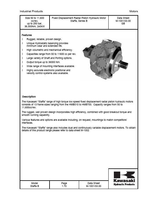
Size 50 to 11,600cc/rev, up to 250 bar, 36,000Nm, 240kW Fixed Displacement Radial Piston Hydraulic MotorStaffa, Series BData Sheet M-1001/03.00GBFeatures ◊ Rugged, reliable, proven design. ◊ Unique Hydrostatic balancing provides minimum wear and extended life.◊ High volumetric and mechanical efficiency. ◊ Capacities range from 50 to 11600 cc per rev. ◊ Large variety of Shaft and Porting options. ◊ Output torque up to 36000 Nm.◊ Wide range of mounting interfaces available. ◊Highly accurate electronic positional and velocity control systems also available.DescriptionThe Kawasaki “Staffa” range of high torque low speed fixed displacement radial piston hydraulic motors consists of 13 frame sizes ranging from the HMB010 to HMB700. Capacity ranges from 50 to 11,600cc/rev.The rugged, well proven design incorporates high efficiency, combined with good breakout torque and smooth running capability.Various features and options are available including, on request, mountings to match competitors’ interfaces.The Kawasaki “Staffa” range also includes dual and continuously variable displacement motors. To obtain details of this product range please refer to data sheet M-1002Model Staffa B Page 1.70 Data Sheet M-1001/03.00Shaft OptionsMOTOR TYPE SHAFT DESCRIPTIONHMB010 P* = Parallel keyed shaft Ø 40mmHMB010 S* = Involute spline 13 teeth BS3550HMB030/045 (H)S* = Involute spline 17 teeth to BS3550HMB030/045 (H)P = Parallel keyed shaft Ø 55mmHMB030/045 (H)Z* = Involute spline to DIN5480 (W55x3x17x7h) HMB045 Q* = Internal involute spline 21 teeth to BS3550 HMB060/080/100 (H)P* = Parallel keyed shaft Ø 60mmHMB060/080/100 (H)S* = Involute spline14 teeth to BS3550HMB060/080/100 (H)Z* = Involute spline to DIN5480 (W70x3x22x7h) HMB060/080/100 (H)Q* = Internal involute spline 24 teeth to BS3550 HMB060/080/100/125/150/200/HMB270/325 T* = Long tapered keyed shaftHMB060/080/100/270/325 X* = Short tapered keyed shaftHMB125/150/200/270/325 (H)P1* = Parallel keyed shaft Ø 85mmHMHDB125/150/200/270 & 325 (H)P2* = Parallel keyed shaft Ø 100mmHMB125/150/200/270/325 (H)S3* = Involute spline 20 teeth to BS3550HMB125/150/200 (H)S4* = Involute spline 16 teeth at 200HMHDB125/150/200, 270/325 (H)S5* = Involute spline 23 teeth to BS3550HMB125/150/200 (H)Z3* = Involute spline to DIN5480 (W85x3x27x7h) HMHDB125/150/200 (H)Z5* = Involute spline to DIN5480 (W100x4x24x7h) HMHDB125/150/200/270/325 (H)Q* = Internal involute spline 34 teeth to BS3550 HMHDB125/150/200/270/325 (H)X* = Short taper, keyed shaftHMB270/325 + HMHDB270/325 (H)Z* = Involute spline to DIN5480 (W100x4x24x7h) HMHDB400 P* = Parallel shaft with two keys Ø 100mm HMHDB400 S* = Involute spline 23 teeth to BS3550 HMHDB400 Z* = Involute spline to DIN5480 (W100x4x24x7h) HMHDB400 Q* = Internal involute spline 31 teeth to BS3550 HMHDB400 X* = Tapered keyed shaftHMB700 Z* = Involute spline to DIN5480 (W120x4x28x7h) HMB700 P = Parallel keyed shaft at 1200 120 ØNotes:* - For installations where shaft is vertically upwards specify “V” after shaft type letter to ensure that additional high level drain port is provided.(H) - Use “H” prefix code as noted to specify “hollow” shaft with through hole Ø 26.2. Hollow shafts are available only with type “S04” main port connection.For all shaft dimensions see the motor installation drawingsModel Staffa B Page3.70Data SheetM-1001/03.00Main Port ConnectionsProduct TypeHMB010Blank = Two, four bolt flange ports of 20mm ØHMB030 Mono blocBlank = Rear entry ports G 3 /4" (BSPF)F = Side port SAE 1" -4 Bolt (UNC) flangeFM = Side port SAE 1" -4 Bolt (Metric) flangeHMB045 Mono blocBlank = Rear entry ports G 1" (BSPF)D = Dual entry ports G 1" (BSPF)HMB030/045 Two part build (TPB)SeedetailbelowHMB060/080/100F2 = SAE 1", 4 Bolt (UNC) flangesFM2 = SAE 1", 4 Bolt (Metric) flangesS03 = 6-Bolt (UNF) flange. (Staffa original valve housing)F3 = SAE 11/4 4 Bolt (UNC) flangesFM3 = SAE 11/4" 4 Bolt (Metric) flangesS04 (1)= 6 Bolt (UNF) flanges. (Staffa original valve housing)HMB125/150/200 + Heavy Duty Variants Details as above, plus the following:F4 = SAE 11/4" 4 Bolt (UNC) flangesFM4 = SAE 11/2" 4 Bolt (Metric) flangesHMB270/325 + Heavy Duty VariantsF4 = SAE 11/2" 4 Bolt (UNC) flangesFM4 = SAE 11/2" 4 Bolt (Metric) flangesS04 (1)= 6 Bolt (UNF) flanges. (Staffa original valve housing) HMHDB400Blank = Combined 6-Bolt flange and 4 Bolt SAE connectionPorts “B” and “C” 6-Bolt UNF flangePorts “A” and “C” SAE, 2" 4-Bolt UNF flangesS045 = 2 x 6 Bolts (UNF) flanges (2 inlet and 2 outlet ports available) HMB700FM = Standard code 62SAE 2" 4 Bolt (Metric) flangesNote:(1)Obligatory for hollow shafts type: HP, HS, HZ or HQModel Staffa B Page4.70Data SheetM-1001/03.00Performance DataIntermittent max pressureB010 up to 241 barB700 up to 250 barAll other models to 293 bar.These pressures are allowable on the following basis:(a) Up to 50 r/min: 15% duty for periods up to 5 minutes maximum.(b) Over 50 r/min: 2% duty for periods up to 30 seconds maximum.Continuous ratingFor continuous duty the motor must be operating within each of the maximum values for speed, pressure and power.Intermittent ratingOperation within the intermittent power rating (up to the maximum continuous speed) is permitted on a 15% duty basis, for periods up to 5 minutes maximum.Limits for fire resistant fluidsPressure,bar Fluid Type Continuous Intermittent Max Speed r/min Model typeHFA 5/95% oil in emulsion 103 138 50% of limits forMineral OilAll modelsHFB 60/40 water inoil emulsion138 172 As for Mineral Oil All modelsHFC water glycol 103 138 50% of limits orMineral OilAll modelsHFD phosphateester207 241 As for Mineral Oil B010207 293 B030250 293 B045 to B400 inc.210 250 B700Model Staffa Page6.70Data SheetM-1001/03.00Performance Data TablesMotortype Geometricdisplacement(cc/rcv) Averageactualrunningtorque(Nm/bar)Max.continuousspeed(rev/min)Max.continuousoutput(kW)Max.continuouspressure.(bar)Max.intermittentpressure(bar)B10 188 2.79 500 25 207 241B030 442 6.56 450 42 207 293 B045 740 10,95 400 60 250 293 B060 983 14.5 300 80 250 293 B060 F2/FM2 983 14.5 200 75 250 293 B080 1344 19.9 300 100 250 293 B080 F2/FM2 1344 19.9 150 77 250 293 B100 1639 24.3 250 110 250 293 B100 F2/FM2 1639 24.3 125 80 250 293 B125 2050 30.66 220 100 250 293 B125 F2/FM2 2050 30.66 100 75 250 293 B150 2470 36.95 220 115 250 293 B150F3/FM3/S032470 36.95 168 115 250 293 B150 F2/FM2 2470 36.95 80 75 250 293 B200 3080 46.07 175 130 250 293B200F3/FM3/S033080 46.07 135 130 250 293 B200 F2/FM2 3080 46.07 65 75 250 293 B270 4310 63.79 125 140 250 293 B325 5310 79.4 100 140 250 293 B400 6800 101 120 190 250 293 B700 11600 171.7 100 240 210 250Model Staffa Page7.70Data SheetM-1001/03.00Non-Standard Displacements Motor Displacements cc/rev HMB010 177 130 94 50 HMB030 492 477 455 330 320 300 278 251 213 HMB045 800 700 634 570 500 440HMB080 1250 1100 1000 HMB100 1530 1500 HMB125 1800 HMB150 **** **** HMB200 3630* 2870 HMHDB200 3630* 2785 HMB270 4588 4500 3688 3600 HMHDB270 4000 HMB325 6100* 5187 HMHDB400 6137 6468 5322 4340 4000 8000*HMB70010600 9600 8850Note:* Reduced pressure and power rating.ModelStaffa Page 8.70 Data Sheet M-1001/03.00HMB270, HMB325 Shaft Types P1, S3, Z, T, XModel StaffaPage16.70Data SheetM-1001/03.00 WA W = Side LoadA = Distance from mountingface to load centreP = Max. pressure onport 1 or port 2N = Shaft speed, r/minHMHDB400 Shaft Types P, S, Z, and XModel StaffaPage17.70Data SheetM-1001/03.00 WA W = Side LoadA = Distance from mountingface to load centreP = Max. pressure onport 1 or port 2N = Shaft speed, r/minCircuit and Application NotesStarting TorqueThe starting torques shown on the graphs on pages 9 to 12 are average and will vary with system parameters.Low Speed OperationsMinimum operating speeds are determined by the hydraulic system and load conditions (load inertia, drive elasticity, etc.) Recommended minimum speeds are shown below:Model Type r/minB010 20B030 5B045 6B06080/100/125/150/200 3B270/B325/HMB400 2B700 1Note: Speed as low as 0.025 rpm can be accurately achieved using electronic control systems.For operation at speeds below these figures please contact Kawasaki Precision Machinery (UK) Ltd. High Back PressureWhen both inlet and outlet ports are pressurised continuously, the lower port pressure must not exceed 70 bar at any time.Note: High back pressure reduces the effective torque output of the motor.Boost PressureWhen operating as a motor the outlet pressure should equal or exceed the crankcase pressure . If pumping occurs (i.e. overrunning loads) then a positive pressure ,”P” ,is required at the motor ports.Calculate “P” (bar) from the operating formulaBoost Formula P= 1+ N2 x V2 + CKWhere P is in Bar, N = motor speed (RPM), V = motor displacement (cc/rev.), C=Crankcase pressure (BAR) and K=a constant from the table below:MOTOR PORTING CONSTANTHMB010 Standard 8 x 10⁸Standard 3.7x10⁹HMB030SO3, F(M)3 7.5 X 10⁹Standard 1.3x10¹⁰HMB045SO3, F(M)3 1.6 X 10¹⁰F(M)2 2.7x10⁹HMB060/080/100F(M)3, S03 1.8 X 10¹⁰F(M)2 4.2 X 10⁹F(M)3, S03 4.0 X 10¹⁰HM(HD)B125/150/200F(M)4, S04 8.0 X 10¹⁰HM(HD)B270/325 F(M)4, S04 7.2 X 10¹⁰Standard 6.0 X 10¹⁰HMHDB400S045 7.2 X 10¹⁰HMB700 Standard 1.3x10¹¹Model Staffa Page26.70Data SheetM-1001/03.00Circuit and Application Notes (continued)The flow rate of oil needed for the make-up system can be estimated from the crankcase leakage figure (see Volumetric Efficiency graphs pages 19 to 29) Allowances should be made for other system losses and also for “fair wear and tear” during the life of the motor, pump and system components.Cooling FlowOperating within the continuous rating does not require any additional cooling.For operating conditions above “continuous”, up to the “intermittent” rating, additional cooling oil may be required.This can be introduced through the spare crankcase drain holes, or in special cases through the valve spool end cap. Consult Kawasaki about such applications.Motor Casing PressureWith the standard shaft seal fitted, the motor casing pressure should not exceed 3.5 bar.Notes:1. The casing pressure at all times must not exceed either the motor inlet or outlet pressure.2. High pressure shaft seals are available for casing pressures of:6 Bar for HMB7009 Bar for HMB 01010 Bar for all remaining frame sizes.3. Check installation dimensions for maximum crankcase drain fitting depth.Hydraulic FluidsDependent on motor (see Ordering Code.) suitable fluids include:(a) Antiwear hydraulic oils.(b) Phosphate ester (HFD fluids )(c) Water glycols ( HFC fluids)(d) 60/40% water-in-oil emulsions ( HFB fluids).(e) 5/95% oil-in-water emulsions (HFA fluids)Reduce pressure and speed limits, see page 6.Viscosity limits when using any fluid except oil-in-water (5/95) emulsions are;Max. off load 2000cSt (9270 SUS)Max. on load 150 cSt (695 SUS)Optimum 50 cSt (232 SUS)Minimum 25cSt (119 SUS)Model Staffa Page27.70Data SheetM-1001/03.00Circuit and Application Notes (continued)Mineral Oil recommendationsThe fluid should be a good hydraulic grade, non-detergent Mineral Oil. It should contain anti-oxidant, anti-foam and demulsifying additives. It should contain antiwear or EP additives. Automatic transmission fluids and motor oils are not recommended.Temperature limitsAmbient min. -30°C (-22°F)Ambient max. + 70°C (158°F)Max. operating temperature range.Mineral Oil Water- containingMin -20°C (-4°F) +10°C (50°F)Max. + 80°C (175°F) +54°C (130°F)Note: To obtain optimum services life from both fluid and hydraulic systems components, a fluid operating temperature of 40°C is recommended.FiltrationFull flow filtration ( open circuit ), or full boost flow filtration ( close circuit ) to ensure system cleanliness to ISO4406/1986 code 18/14 or cleaner.Noise levelsThe airborne noise level is less than 66.7 dB(A) DIN (&) dB (A) NFPA) through the “continuous” operating envelope. Where noise is a critical factor, installation resonances can be reduced by isolating the motor by elastomeric means from the structure and the return line installation. Potential return line resonances originating from liquid borne noise can be further attenuated by providing a return line back pressure of 2 to 5 bar.Polar Moment of Inertia & Mass:Model Type Polar moment of Inertia(kg.m2)(Typical data)Mass (kg) (Approx. all models)HMB010 0.0076 40 HMB030 0.015 73 HMB045 0.047 120 HMB060 0.055 144 HMB080 0.060 144 HMB100 0.076 144 HMB125 0.22 217 HMB150 0.25 265 HMB200 0.27 265 HMB270 0.91 420 HMB325 0.95 429 HMHDB400 (With 4" valve) 0.54 481 HMHDB400 (With 4.5" valve) 0.54 510 HMB700 2.38 1050Model Staffa Page28.70Data SheetM-1001/03.00Crankcase Drain Motor axis horizontal.The crankcase drain must be taken from a position above the horizontal centre line of the motor to ensure lubrication of the shaft bearing Axis vertical, shaft down.Use either drain position. The drain line should be run above the level of the uppermost bearing. If there is a risk of syphoning then a syphon breaker should be fitted. Axis vertical, shaft up.An additional G 1/4" (BSPF) drain port is provided when “V” (shaft vertically upwards) designator is given after the shaft type (see Ordering Code). This additional drain should be connected into the main motor casing drain line downstream of a 0.35 bar check valve to ensure lubrication of the upper bearing, see diagram.Installation Data GENERAL Spigot:The motor should be located by the mounting spigot on a flat, robust surface using correctly sized bolts. The diametrical clearance between the motor spigot and the mounting must not exceed 0.15mm. If the application incurs shock loading, frequent reversing or high speed running , then high tensile bolts should be used , including one fitted bolt. Bolt Torque:The recommended torque wrench setting for bolts are as follows: M12 97 +/- 7NmM14 160 +/- 21Nm M18 312 +/- 14Nm M20 407 +/- 14Nm M24 690+/- 27Nm 1/2" UNF 97+/- 7Nm 5/8" 265 +/- 14 Nm 3/4" bolts 393 +/- 14 Nm1" 810+/- 27NmShaft Coupling:Where the motor is solidly coupled to a shaft having independent bearings the shaft must be aligned to within 0.13mm TIRModel Staffa Page 29.70 Data Sheet M-1001/03.00。

r语言找数据集缺失值-回复[R语言找数据集缺失值]在数据分析的过程中,我们常常会遇到数据集中存在缺失值的情况。
缺失值的出现可能是由于数据采集过程中的错误,或者是样本选取过程中的问题,也可能是由于一些主观原因而造成的数据缺失。
无论是哪种原因,对于数据分析来说,缺失值的存在都会对结果产生一定影响。
因此,如何发现和处理缺失值成为数据分析过程中的一个重要环节。
在R语言中,我们可以利用一些函数和方法来发现数据集中的缺失值,并进行相应的处理。
下面,我将一步一步地回答如何在R语言中找到数据集中的缺失值。
第一步:导入数据集首先,我们需要导入我们想要分析的数据集。
R语言可以读取各种格式的数据,如csv、Excel、txt等。
我们可以使用read.csv()函数来读取csv 文件,read.xlsx()函数来读取Excel文件,read.table()函数来读取txt文件等。
假设我们的数据集保存在一个名为data的数据框中,我们可以使用以下命令来导入数据集:data <- read.csv("data.csv")第二步:检查数据集中的缺失值在导入数据集后,我们需要先检查一下数据集中是否存在缺失值。
在R语言中,我们可以使用is.na()函数来检查缺失值。
is.na()函数会将数据集中的每一个元素进行判断,若为空值或缺失值,则返回TRUE,否则返回FALSE。
我们可以使用sum()函数来统计返回TRUE的个数,从而得到数据集中缺失值的总数。
以下是一个示例代码:missing_values <- sum(is.na(data))在执行以上代码后,missing_values变量将会保存数据集中缺失值的个数。
第三步:找到缺失值所在的位置在第二步中,我们已经知道了数据集中缺失值的个数,但我们还不知道缺失值所在的具体位置。
在R语言中,我们可以使用which()函数来找到缺失值所对应的行数和列数。

Package‘rticulate’October14,2022Type PackageTitle Ultrasound Tongue ImagingVersion1.7.3Date2022-09-04Maintainer Stefano Coretta<*************************>Description A tool for processing ArticulateAssistant Advanced™(AAA)exportfiles and plot tongue contour data from any system.URL https:///stefanocoretta/rticulateBugReports https:///stefanocoretta/rticulate/issues Depends R(>=3.0.0)Encoding UTF-8LazyData trueImports dplyr,ggplot2,glue,magrittr,mgcv,purrr,readr,rlang,stats,tibble,tidymv,tidyr,tidyselectRoxygenNote7.2.1Suggests knitr,rmarkdown,stringrVignetteBuilder knitrLanguage en_GBLicense MIT+file LICENSENeedsCompilation noAuthor Stefano Coretta[aut,cre]Repository CRANDate/Publication2022-09-0416:20:02UTC12get_origin R topics documented:get_origin (2)palate (3)plot_polar_smooths (4)plot_tongue (5)polar_gam (6)predict_polar_gam (7)read_aaa (8)stimuli (9)tongue (10)transform_coord (11)Index12 get_origin Get the origin of spline dataDescriptionIt returns the Cartesian x,y coordinates of the virtual origin of the ultrasonic waves/probe surface (see Details).Usageget_origin(data,fan_lines=c(10,25))Argumentsdata The spline data(the cartesian coordinates must be in two columns named X and Y).fan_lines A numeric vector with two fan lines(the default is c(10,25)).DetailsThe function estimates the origin of the ultrasond waves from the probe using the spline data and the provided fan lines.The estimation method is based on Heyne,Matthias&Donald Derrick (2015)Using a radial ultrasound probe’s virtual origin to compute midsagittal smoothing splines in polar coordinates.The Journal of the Acoustical Society of America138(6),EL509–EL514, DOI:10.1121/1.4937168.ValueA numeric vector with the Cartesian(x,y)coordinates of the virtual origin of the ultrasonicwaves/probe surface.palate3 Origin estimationThe equations of the two fan lines(10and25by default)are set equal tofind their intersection.The intersection is the origin.In some cases,the linear estimation of the equation fails,and an error related tofit is returned.In these cases,try different fan lines by increasing the minimum fan line and/or changing the maximum fan line(for example,if c(10,25)returns an error,try c(15,30)).palate Palate profile dataset.DescriptionA dataset containing the palate profile of a single speaker.UsagepalateFormatA data frame with42rows and14variables.speaker speaker IDseconds time of coordinate,in secondsrec_date date and time of recordingprompt prompt stringlabel label of annotationTT_displacement smoothed displacement of tongue tipTT_velocity velocity of tongue tip displacementTT_abs_velocity absolute velocity of tongue tip displacementTD_displacement smoothed displacement of tongue dorsumTD_velocity velocity of tongue dorsum displacementTD_abs_velocity absolute velocity of tongue dorsum displacementfan_line fan line numberX horizontal coordinate at time secondsY vertical coordinate at time seconds4plot_polar_smooths plot_polar_smooths Plot smooths from a polar gamDescriptionIt plots the smooths of a polar GAMfitted with polar_gam().Usageplot_polar_smooths(model,series,comparison=NULL,origin=NULL,facet_terms=NULL,conditions=NULL,exclude_random=TRUE,series_length=100,split=NULL,sep="\\.",time_series)Argumentsmodel A gam or bam model object.series An unquoted expression indicating the model term that defines the series on which smoothing is applied.This is the term that is displayed on the x-axiswhen plotting.comparison An unquoted expression indicating the model term for which the comparison will be plotted.origin The coordinates of the origin as a vector of c(x,y)coordinates.facet_terms An unquoted formula with the terms used for faceting.conditions A list of quosures with quos specifying the levels to plot from the model terms not among series,comparison,or facet_terms.exclude_random Whether to exclude random smooths(the default is TRUE).series_length An integer indicating how many values along the time series to use for predicting the outcome term.split Columns to separate as a named list.sep Separator between columns(default is"\.",which is the default with).If character,it is interpreted as a regular expression.time_series Deprecated,use series instead.plot_tongue5 ValueAn object of class ggplot.Exampleslibrary(dplyr)tongue_it01<-filter(tongue,speaker=="it01")pgam<-polar_gam(Y~s(X,by=as.factor(label)),data=tongue_it01)plot_polar_smooths(pgam,X,label)plot_tongue Plot tongue contours from spline data.DescriptionIt plots tongue contours from data imported from AAA.Usageplot_tongue(data,geom="line",...,palate=NULL,palate_col="green")Argumentsdata A data frame with splines data.geom Type of geom to plot.Possible values are:line(the default),point,path....List of arguments to be passed to geom.palate An optional data frame with the palate spline.If provided,the palate is plotted.palate_col The colour of the palate spline(the default is green).ValueAn object of class ggplot.Examplesplot_tongue(tongue,geom="point")6polar_gam polar_gam Polar generalised additive model(polar GAM)DescriptionItfits a generalised additive model(GAM)to transformed polar tongue data and it returns a model in polar e plot_polar_smooths()for plotting.Usagepolar_gam(formula,data,origin=NULL,fan_lines=c(10,25),AR_start=NULL,...)Argumentsformula A GAM formula.data A data set containing the spline coordinates(cartesian coordinates must be in columns named X and Y,polar coordinates in columns named angle and radius;these are the defaults in data imported with read_aaa()).origin The coordinates of the origin as a vector of c(x,y)coordinates.fan_lines A numeric vector with two fan lines(the default is c(10,25)).AR_start The AR.start argument to be passed to mgcv::bam()....Arguments to be passed to mgcv::bam().DetailsIt is advised tofit a separate model per speaker,unless you have a working method for inter-speaker normalisation of the coordinates.ValueAn object of class"gam"as described in gamObject.Exampleslibrary(dplyr)tongue_it01<-filter(tongue,speaker=="it01")pgam<-polar_gam(Y~s(X,by=c2_place)+s(X,word,bs="fs"),data=tongue_it01)predict_polar_gam7 predict_polar_gam Get all predictions from a polar GAM modelDescriptionIt returns a tibble with the predictions from all the terms in a polar_gam model.Usagepredict_polar_gam(model,origin=NULL,exclude_terms=NULL,length_out=50,values=NULL,return_ci=FALSE,ci_z=1.96)Argumentsmodel A polar_gam model object.origin The coordinates of the origin as a vector of c(x,y)coordinates.exclude_terms Terms to be excluded from the prediction.Term names should be given as they appear in the model summary(for example,"s(x0,x1)").length_out An integer indicating how many values along the numeric predictors to use for predicting the outcome term(the default is50).values User supplied values for numeric terms as a named list.return_ci Whether to return a tibble with cartesian confidence intervals(for use with geom_polar_ci).ci_z The z-value for calculating the CIs(the default is1.96for95percent CI).DetailsThe function behaves like predict_gam but it converts the coordinates from polar to cartesian auto-matically.Check vignette("predict-gam",package="tidymv")to an overview of the predict method.To see an example of plotting,see the examples in geom_polar_ci.ValueA tibble with predictions from a polar_gam model.8read_aaa Exampleslibrary(dplyr)tongue_it01<-filter(tongue,speaker=="it01")it01_pol<-polar_gam(Y~s(X,by=c2_place)+s(X,word,bs="fs"),data=tongue_it01)#get predictionsit01_pred<-predict_polar_gam(it01_pol)#get predictions excluding the random smooth for word(the coefficient for#the random smooth is set to0)it01_excl_rand<-predict_polar_gam(it01_pol,exclude_terms="s(X,word)")read_aaa Read tab separatedfiles with AAA spline data.DescriptionIt reads afile or a list offiles with data exported from AAA.The data are automatically transformed from a wide to a long format(each row has values of X or Y axes for each fan line).The imported tibble can then be used for plotting and statistical analysis.Usageread_aaa(file,column_names,fan_lines=42,coordinates="cartesian",na_rm=FALSE,format="long")Argumentsfile The path of thefile with AAA data.It can also be a character vector with multi-ple paths as separate strings..column_names The names of the columns without including the splines columns.fan_lines The number of fan lines(the default is42).coordinates A string specifying the coordinate system.Possible values are"cartesian"(the default)and"polar".na_rm Remove NAs(the default is FALSE).format A string specifying the data format.Possible values are"long"and"wide"(the default is"long").stimuli9 ValueA tibble.An.index column is added which indexes(groups)each tongue contour.Examplescolumns<-c("speaker","seconds","rec_date","prompt","label","TT_displacement","TT_velocity","TT_abs_velocity","TD_displacement","TD_velocity","TD_abs_velocity")file_path<-system.file("extdata","it01.tsv",package="rticulate")tongue<-read_aaa(file_path,columns,na_rm=TRUE)stimuli Stimuli dataset.DescriptionA dataset with linguistic information on the stimuli.UsagestimuliFormatA data frame with12rows and11variables.item item IDword words of the form CVCVipa IPA transcription of the wordsc1first consonantc1_phonation phonation of thefirst consonant,voicelessvowelfirst and second vowelanteropost backness of the vowel,back or centralheight height of the vowel,high,mid or lowc2second consonantc2_phonation phonation of the second consonant,voiceless or voicedc2_place place of the second consonant,coronal or velar10tongue tongue Tongue contours dataset.DescriptionA dataset containing tongue contour coordinates of a single speaker.UsagetongueFormatA data frame with3612rows and28variables.speaker speaker IDseconds time of coordinate,in secondsrec_date date and time of recordingprompt prompt stringlabel label of annotationTT_displacement smoothed displacement of tongue tipTT_velocity velocity of tongue tip displacementTT_abs_velocity absolute velocity of tongue tip displacementTD_displacement smoothed displacement of tongue dorsumTD_velocity velocity of tongue dorsum displacementTD_abs_velocity absolute velocity of tongue dorsum displacementTR_displacement smoothed displacement of tongue rootTR_velocity velocity of tongue root displacementTR_abs_velocity absolute velocity of tongue root displacementfan_line fan line numberX horizontal coordinate at time secondsY vertical coordinate at time secondsword words of the form CVCVitem item IDipa IPA transcription of the wordsc1first consonantc1_phonation phonation of thefirst consonant,voicelessvowelfirst and second vowelanteropost backness of the vowel,back or centralheight height of the vowel,high,mid or lowc2second consonantc2_phonation phonation of the second consonant,voiceless or voicedc2_place place of the second consonant,coronal or velartransform_coord11 transform_coord Transform the coordinates of spline dataDescriptionThis function transforms the coordinates of spline data between Cartesian and polar coordinate systems.The origin x and y coordinates can be supplied by the user,or calculated automatically (see Details).Usagetransform_coord(data,to="polar",origin=NULL,fan_lines=c(10,25),use_XY=FALSE)Argumentsdata A data set containing the spline coordinates(cartesian coordinates must be in columns named X and Y,polar coordinates in columns named angle and radius;these are the defaults in data imported with read_aaa()).to Which system to convert to,as a string,either"polar"or"cartesian"(the default is"polar").origin The coordinates of the origin as a vector of c(x,y)coordinates.fan_lines A numeric vector with two fan lines(the default is c(10,25)).use_XY Whether to use the column names X and Y when converting to and from polar coordinates,rather than the default angle and radius(the default is FALSE.IfTRUE,the columns X and Y are overwritten with the converted values.If convert-ing to polar,X is the angle and Y the radius.DetailsThe transformation between the coordinate systems require the selection of an origin in Cartesian coordinates(x and y).The origin ideally corresponds to the virtual origin of the ultrasound waves from the probe.The origin coordinates can be supplied by the user as a vector with the origin argument,or they can be estimated automatically if origin=NULL(the default).The estimation is performed by get_origin(see that function documentation for details).ValueAn object of class tbl_df-class(a tibble).Index∗datasetspalate,3stimuli,9tongue,10gamObject,6geom_polar_ci,7get_origin,2,11ggplot,5palate,3plot_polar_smooths,4plot_tongue,5polar_gam,6,7predict_gam,7predict_polar_gam,7read_aaa,8stimuli,9tongue,10transform_coord,1112。
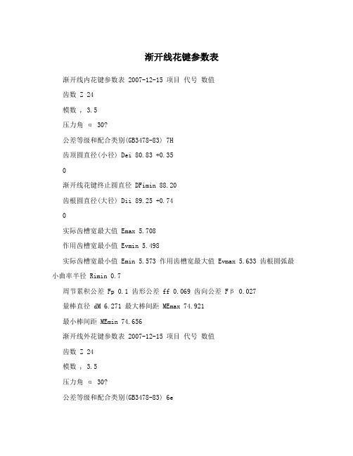
渐开线花键参数表渐开线内花键参数表 2007-12-15 项目代号数值齿数 Z 24模数 , 3.5压力角α 30?公差等级和配合类别(GB3478-83) 7H齿顶圆直径(小径) Dei 80.83 +0.35渐开线花键终止圆直径 DFimin 88.20齿根圆直径(大径) Dii 89.25 +0.74实际齿槽宽最大值 Emax 5.708作用齿槽宽最小值 Evmin 5.498实际齿槽宽最小值 Emin 5.573 作用齿槽宽最大值 Evmax 5.633 齿根圆弧最小曲率半径 Rimin 0.7周节累积公差 Fp 0.1 齿形公差 ff 0.069 齿向公差Fβ 0.027量棒直径 dM 6.271 最大棒间距 MEmax 74.921最小棒间距 MEmin 74.656渐开线外花键参数表 2007-12-15 项目代号数值齿数 Z 24模数 , 3.5压力角α 30?公差等级和配合类别(GB3478-83) 6e齿顶圆直径(大径) Dee 87.50 -0.125-0.475渐开线花键起始圆直径 DFemax 80.03齿根圆直径(小径) Die 78.75 -0.125-0.865实际齿厚最大值 Smax 5.376作用齿厚最小值 Svmin 5.345实际齿厚最小值 Smin 5.295作用齿厚最大值 Svmax 5.426齿根圆弧最小曲率半径 Remin 0.7周节累积公差 Fp 0.07齿形公差 ff 0.043 齿向公差Fβ 0.017量棒直径 dM 6.862 最大跨棒距 MSmax 94.621最小跨棒距 MSmin 94.495involute spline data:渐开线花键参数flat root side fit : 平齿根齿侧定心pith(应为pitch):径节 14/32 number of teeth:齿数 19 pressure angle :压力角 30base cicle dia (ref) :基圆直径 1.0284cicular space width:分度圆齿槽宽min effective:最小作用齿槽宽 0.0982max effective(ref) :最大作用齿槽宽 0.0997min actual(ref):最小实际齿槽宽 0.0992max actual :最大实际齿槽宽 0.1007 max mesaurement between two 0.0900 dia pins:在量棒直径0.09之间的量棒距最大值1.0878involute profile error :齿形误差 +0.0003 -0.0005 total index error max :相当于齿距累积误差 0.0015mat parallelism error:齿向误差 0.0005Total Index Error - (The maximum amount of displacement from the theoretical angularposition of any tooth with respect to any other tooth on a spline) 楼上翻译得不错~仅补充一下base cicle dia (ref) :基圆直径(参考) 1.0284min effective:最小有效齿槽宽 0.0982max effective(ref) :最大有效齿槽宽(参考) 0.0997min actual(ref):最小实际齿槽宽(参考) 0.0992 max mesaurement between two 0.0900 dia pins:量棒距最大值1.0878 量棒直径 0.0900min effective专业名称应为“最小作用齿槽宽”(如图摘自GB/T 3478.1-1995圆柱直齿渐开线花键)。
High Torque,Low Speed MotorsH, S, 2000, 6000, and 10,000 SeriesENGINEERING DATAInterchangeable with:• Charlynn • White • Ross • ParkerINDEXCross Reference Guide (2)Introduction (3)H-Series (4)Shaft Data (5)Model Code (5)Installation Data (5)Shaft Seal (6)Case Drain (6)Shaft Rotation (6)Radial Forces (6)Technical Data..........................................7-9 S-Series. (10)Shaft Data (11)Model Code (11)Installation Data (11)Shaft Seal (12)Case Drain (12)Shaft Rotation (12)Radial Forces (12)Technical Data........................................12-15 2000-Series. (16)Shaft Data (17)Model Code..............................................17 Installation Data......................................18-19 Shaft Seal (20)Case Drain (20)Shaft Rotation (20)Radial Forces (20)Technical Data........................................21-23 6000-Series. (24)Shaft Data (25)Model Code (25)Installation Data (26)Shaft Seal (26)Case Drain (26)Shaft Rotation (26)Radial Forces (26)Technical Data........................................27-29 10,000-Series.. (30)Shaft Data (31)Model Code (31)Installation Data (32)Shaft Seal (33)Case Drain (33)Shaft Rotation (33)Radial Forces (33)Technical Data........................................34-35MOTOR CROSS-REFERENCE GUIDE1-800-842-5377Western FluiDyne Eaton/Charlynn White Danfoss Parker Ross/ TRWH Series A, H (130-,101-)RS (200-)DH, OMP TC, TB, MK, MGS Series S, T (103-, 158- )WR (255-)OMR, DS (151-)TB, TE, MG, MF 2000 Series2000 (104-)HB, RE (300-, 500-)OMS, OME TF, TG, MB, ME 6000 Series4K, 6K (109-,112-)RE, DR (500-, 600-)OMT, TMK, TMT TG, TH, TK, ME, MJ 10,000 Series10K (119-)DT OMV, TMVWestern FluiDyne reserves the right to make alterations to it's product.HIGH TORQUE, LOW SPEED MOTORS1-800-842-5377 Western FluiDyne LSHT Hydraulic MotorsWestern FluiDyne’s extensive range of multiple displacement Low Speed – High Torque (LSHT) hydraulic motors are formfit and function interchangeable with many of the common motor products from Parker, White, Charlynn and Danfoss.Both Geroter and Geroler technologies are incorporated in the Western FluiDyne “H” Series, “S” series, “2000” series,“6000” series and “10,000” series.These Western FluiDyne motors are manufactured with ISO 9001:2000 documented quality standards which results inproduct which consistently meets or exceeds the life and performance expectations of similar products.The Western FluiDyne product is built to perform in even the harsh environments where rugged mobile equipment is ex-pected to operate. For optimal life the following guidelines are recommended:1) Motors should be operated at less than 30% of full rated performance for the first hour of operation2) During normal sustained operations, oil temperature should be between 70 to 150 degrees F (20 to 60 degrees C)3) Maximum operating temperature should not exceed 190 degrees F (90 degrees C)4) ISO oil cleanliness level should be 18/13 or cleaner. Normally this is achieved with Beta 10=100 full flow returnline filtration.5) High grade petroleum based hydraulic oil must be used6) Minimum oil viscosity should be 100 SUS7) Simultaneous maximum torque and maximum speed is not recommend for this design of motorTechnical Data Summary:Model Distributor Displacement Maximum Speedtype Operating Pressure RPMin3/rev cm3/rev PSI BARH Series Axial3-2350-400240016330-800S Series Axial3-2350-375300020030-9702000 Series Disc5-2380-375325022530-8006000 Series Disc10-49160-800340024030-70510,000 Series Disc19-49315- 800400028010-446HIGH TORQUE, LOW SPEED MOTORS1-800-842-5377 H-SERIESThe -101 (H) Geroter™ gear set, spool valve flow distribution, hydraulic motors are a compact, highly efficient, low speed-high torque design which can be used in either parallel or series systems. These low weight advanced construction designmotors are manufactured in accordance with the requirements of the ISO 9001:2000 quality system.Technical SpecificationsFLUIDYNE 101 H SERIESContinuous = maximum of continuous operationIntermittent = maximum operating range for 6 seconds per minuteM0H - 50 - A - 01 - B - O - OH SERIES (-101)FRAME SIZE (In3/REV)36 (2.20)50 (3.15)80 (4.74)100 (5.87)125 (7.20)160 (9.51)200 (11.59)250 (14.09)315 (19.02)400 (24.4)H SERIES MODEL CODE (-101)MOUNTING FLANGE TYPEA - 2 BOLT-SAE - “A”B - 4 BOLT SQUARE K - 4 BOLT MAGNETODRIVE SHAFT01 - 1” Woodruff Key 02 - SAE 6B SplinePORT SIZE A - 7/8 -14 SAE B - 1/2 NPTF C - ManifoldSPECIAL OPTIONS 00 - None01 - Reverse Rotation 02 - Flange Rotated 90˚AA - Free Running*AC - Viton Shaft Seal0 -No Paint 1 - Black Paint NP - Nickel PlatedAdditional flange and drive shaft options available please consult factory *Available on selected modelsHIGH TORQUE, LOW SPEED MOTORS1-800-842-5377K - MAGNETOMANIFOLD MOUNTH-SERIES SHAFT DATAA- SAE -“A” 2 BOLT B - 4 BOLT SQUARESAE 6B Spline01021” Woodruff KeyWoodruff Keyed 1”x.25H SERIES INSTALLATION DATAHIGH TORQUE, LOW SPEED MOTORS1-800-842-537736 CM 3/REVH 36 (02/022)2.20 IN 3/REV Max Cont. Max Int.51.7 CM 3/REVH 50 (03/028)3.15 IN 3/REV Max Cont. Max Int.HIGH TORQUE, LOW SPEED MOTORS1-800-842-5377H SERIES TECHNICAL DATA77.7 CM3/REVH 80 (05/045) 4.74 IN3/REV Max Cont. Max Int.96.2 CM3/REVH 100 (06/059) 5.87 IN3/REV Max Cont. Max Int.117.9 CM3/REVH 125 (07/073)7.20 IN3/REV Max Cont. Max Int.HIGH TORQUE, LOW SPEED MOTORS1-800-842-5377H SERIES TECHNICAL DATA156 CM3/REVH 160 (10/097)9.51 IN3/REV Max Cont. Max Int.190 CM3/REVH 200 (11/113)11.50 IN3/REV Max Cont. Max Int.231 CM3/REVH 250 (14/141)14.09 IN3/REV Max Cont. Max Int.HIGH TORQUE, LOW SPEED MOTORS1-800-842-5377 H SERIES TECHNICAL DATA312 CM3/REVH 315 (18/179)19.03 IN3/REV Max Cont. Max Int.387 CM3/REVH 400 (23/226)23.61 IN3/REV Max Cont. Max Int.HIGH TORQUE, LOW SPEED MOTORS1-800-842-5377 S-SERIESThe -103(S) series advanced GEROLER™ gear set hydraulic motor, with spool valve flow distribution, is a compact, lownoise, high efficient high torque low speed design. The GEROLER™ gear set also provides higher efficiencies at start upand during low speed conditions.The special design of the valve linkage and high pressure capability of the shaft seal provides a long operating life andthese motors can be used in either series or parallel operation.The low weight advanced construction design is manufactured in accordance with the requirements of ISO 9001:2000quality system.Technical SpecificationsFLUIDYNE 103 S SERIESContinuous = maximum of continuous operationIntermittent = maximum operating range for 6 seconds per minuteM0S - 50 - A - 01 - A - 0 - 1S SERIES-103FRAME SIZE(IN3/REV)50 (3.05)80 (4.92)100 (6.15)125 (7.63)160 (9.60)200 (12.16)250 (15.38)315 (19.20)375 (22.60)S SERIES MODEL CODEMOUNTING FLANGE TYPE A - 2 BOLT SAE-AB - 4 BOLT Square Mount K - 4 BOLT MagnetoDRIVE SHAFT01 - 1” Woodruff Key 02 - SAE 6B SplinePORT SIZE A - 7/8 -14 SAE B - 1/2 NPTF C - Manifold0 - No Paint 1 - BlackNP - Nickel PlateSPECIAL OPTIONS 0 - None01 - Reverse Rotation 02 - Flange Rotated 90˚AA - Free Running*AC - Viton Shaft SealDS - High Pressure Shaft SealAdditional flange and drive shaft options available please consult factorySAE 6B Spline0102* Available on selected modelsS-SERIES SHAFT DATAA- SAE -“A” 2 BOLTK - MAGNETOB - 4 BOLT SQUAREC - MANIFOLDS SERIES INSTALLATION DATA1” Woodruff KeyWoodruff Keyed 1”x.25SHAFT ROTATION DIRECTION RADIAL FORCESSTANDARD ROTATION VIEWEDFROM SHAFT ENDPort A pressurized = CW rotationPort B pressurized = CCW rotation51.3 Cm3/RevS 50 3.13 in3/Rev Max Cont. Max Int.80.6 Cm3/RevS 80 4.9 in3/Rev Max Cont. Max Int.100.8 Cm3/RevS 100 6.15 in3/Rev Max Cont. Max Int.124.9 Cm3/RevS 1257.63 in3/Rev Max Cont. Max Int.157.2 Cm3/RevS 1609.60 in3/Rev Max Cont. Max Int.199.2 Cm3/RevS 20012.16 in3/Rev Max Cont. Max Int.252 Cm3/RevS 25015.39 in3/Rev Max Cont. Max Int.314.5 Cm3/RevS 31519.2 in3/Rev Max Cont. Max Int.370 Cm3/RevS 37522.6 in3/Rev Max Cont. Max Int.2000-SERIESThe 2000 series motor adapts the advanced Geroler™ gear set design with DISC flow distribution and high pressure. The output shaft tapered roller bearings permit high axial and radial forces offering a smooth operation during low pressure start up and high pressure operation. These low weight advanced construction design motors are manufactured in accordance with the requirements of the ISO 9001:2000 quality system.Technical SpecificationsFLUIDYNE 104 2000 SERIESContinuous = maximum of continuous operationIntermittent = maximum operating range for 6 seconds per minuteM02 - 200 - AC - 01 - AG - 1 - O2000 SERIES (-104)FRAME SIZE (IN3/REV)80(4.90)100(6.20)125(7.20)160(9.59)200(12.20)250(15.40)315(19.20)400(24.04)475(28.98)MODEL CODE - 2000 SERIESMOUNTING FLANGE TYPEAC - SAE -“A” 2 BOLT AB - 4 BOLT Wheel AF - SAE - “B” 2 BOLT AH - 4 BOLT Square AJ - 4 BOLT Magneto AD - 4 BOLT BearinglessDRIVE SHAFT01 - 1” Woodruff Key 02 - 1-1/4” Parallel Key03 - 1-1/4" Tappered Shaft SAE J50104 - 1-1/4" 14 Tooth Spline 05 - 1” SAE 6B Spline07 - 7/8" 13 Tooth 16/32 DPPORT SIZEAA - 7/8” -14 SAE O-Ring AB - ManifoldAF - 1 1/16”-12 SAE O-Ring 180˚ Apart AG - G-1/2 BSPAP - All Port (7/8”-14, 1-1/16”-12,2x3/8” UNC Thread)0 - No Paint 1 - BlackNP - Nickel PlateSPECIAL OPTIONS 0 -None01 - Viton Seals 03 - Free Running*31 - Dual Cross Port Reliefs 41 - High Pressure Shaft Seal*B - Reverse RotationAdditional flange and drive shaft options available please consult factory01020304*Available on selected models2000-SERIES SHAFT DATAShaft 01: 1” woodruff keyed Woodruff key Ø25.4x6.35Shaft 03: 1-1/4” Tapered Parallel key .31x.31x1.0Tightening torque: 200±10NmShaft 04:1-1/4” 14 Tooth Spline 12/24 DP0507Shaft 05: 1” SAE 6B SplineShaft 07:7/8”-13 Tooth Spline 16/32 DPShaft 02: 1-1/4 Keyed Parallel key .31x.31x1.25[INCHES] MILLIMETERSMODEL L L1L L180[6.93][0.63]17616100[7.09][0.79]18020125[7.28][0.98]18525160[7.36][1.06]18727200[7.64][1.34]19434250[7.95][1.65]20242315[8.43][2.13]21454400[9.02][2.72]22969475[9.57][3.27]24383Rear Housing Drain Port[INCHES] MILLIMETERSMODELL L1L2L L1L280[6.81][.51][4.95]17313125.7100[6.97][.67][5.11]17717129.7125[7.17][.87][5.30]18222134.7160[7.38][1.08][5.52] 187.527.5140.2200[7.68][1.38][5.81]19535.1147.7250[8.15][1.85][6.29]20747159.7315[8.62][2.32][6.76]21959171.7375[9.09][2.80][7.23]23171183.7180° APART PORT MOUNTING DATADRAIN ON REAR HOUSING2000 SERIES INSTALLATION DATA[INCHES] MILLIMETERSMODEL L L1L2L L1L280[6.74][.52][4.85]17113123.2100[6.89][.67][5.01]17517127.2125[7.09][.87][5.21]18022132.2160[7.27][1.09][5.43]184.527.5137.7200[7.60][1.39][5.72]19335.1145.2250[8.07][1.85][6.19]20547157.2315[8.55][2.33][6.67]21759169.2375[9.02][2.80][7.14]22971181.2AB - MANIFOLDAP - ALL PORTSORDER CODE AG Depth AA Depth AF Depth pORtS - A AND B G 1/2 18 mmM22x1.5 18 mm 7/8-14 O-ring 18 mm tANK pORt - tG 1/4 12 mmM14x1.5 12 mm7/16-20 UNF 12 mmpORt & DRAIN pORt ORDERING CODESAF - SAE “B” 2 BOLT AC - SAE “A” 2 BOLTAH - 4 BOLT SQUARE AJ - 4 BOLT MAGNETOAB - 4 BOLT WHEEL MOUNT2000 SERIES INSTALLATION DATA1.83 (46.5)STANDARD ROTATION MODEL L L1L2L L1L280[5.28][0.52][3.39]1341386100[5.44][0.67][3.55]1381790125[5.63][0.87][3.74]1432295160[5.85][12.90][3.96]148.527.5100.5200[6.15][1.39][4.26]15635.1108250[6.62][1.85][4.73]16847120315[7.09][2.33][5.20]180********[7.56][2.80][5.67]19271144[INCHES] MILLIMETERS2000 SERIES BEARINGLESS MOUNTING DATAInternal Spline Data for 2000-Series Bearingless MotorFILLET ROOT SIDE FIT mm 1.Internal spline in mating part to be as follows: Material to be ASTM A304, 8620H. Carborize to a hardness of 58-62 HRC with case depth (to 50HRC) of 0.75-1 [.030-.040] (dimensions apply after heat treat).2. Mating part to have critical dimensions as shown. Oil holes must be provided and open for proper oil circulation.3. Some means of maintaning clearance between shaft and mounting flange must be provided4. Seal to be furnished with motor for proper oil circulation thru splines5. Counterbore designed to adapt to a standard sleeve bearing 35.040 [1.3784-1.3795] ID by 44.040-44.070 [1.7339-1.7350] O.D.(Oilite Bronze sleeve bearing AAM3544-22)80.6 Cm3/Rev2000 SERIES 80 4.92 in3/Rev Max Cont. Max Int.100.8 Cm3/Rev2000 SERIES 100 6.15 in3/Rev Max Cont. Max Int.125 Cm3/Rev2000 SERIES 1257.65 in3/Rev Max Cont. Max Int.154 Cm3/Rev2000 SERIES 1609.39 in3/Rev Max Cont. Max Int.200 Cm3/Rev2000 SERIES 20012.2 in3/Rev Max Cont. Max Int.243 Cm3/Rev2000 SERIES 25014.8 in3/Rev Max Cont. Max Int.311 Cm3/Rev2000 SERIES 31518.9 in3/Rev Max Cont. Max Int.394 Cm3/Rev2000 SERIES 40024 in3/Rev Max Cont. Max Int.475 Cm3/Rev2000 SERIES 47528.9 in3/Rev Max Cont. Max Int.6000-SERIESThe 6000 series motor is a large volume, disc valve, high pressure motor, with a radial ball-bearing design. They are capable of handling greater loads and higher torque applications. The advance design in disc distribution flow provides improved perform-ance at low speed. The disc valve compensates for wear providing volumetric efficiencies. The double taper roller bearings allow for high radial loads making these motors ideal for heavier vehicles in traction drive applications.These low weight advanced construction design motors are manufactured in accordance with the requirements of the ISO 9001:2000 quality system.Technical SpecificationsFLUIDYNE 112 6000 SERIESContinuous = maximum of continuous operationIntermittent = maximum operating range for 6 seconds per minute1-1/2’ KeyedParallel Key .37x.37x1.65M06 - 490 - B - 01 - A - 1 - O6000 SERIES (-112)FRAME SIZE (IN3/REV)195 (11.9)245 (15.0)310 (19.0)395 (24.2)490 (30.0)625 (38.0)800 (49.0)985 (60.0)MODEL CODE - 6000 SERIESMOUNTING FLANGE TYPEA - BEARINGLESS 4-BOLTB - 4 BOLT (SAE CC)C - 4 BOLT WHEEL MOUNT H - 4 BOLT GLOBAL (ISO)DRIVE SHAFT 00 - Bearingless01 - 1-1/2” Parallel Key 02 - 1-3/4" Tapered Key 03 - 1-1/2-17 Tooth Spline 10 - 40mm Straight Key 21 - 50mm Straight Key(avail on mounting flange H only)41 - 1-1/4" Straight KeyPORT SIZEA - 1-5/16"-12 SAE C - G1 (BSP)T - 1-1/16"-12 SAE V - G3/4 (BSP)PAINT 0 - No Paint 1 - BlackNP - Nickel PlatedOPTIONS 00 - None10 - Viton Shaft Seal 13 - Reverse Rotation 65 - Free Running*Additional flange and drive shaft options available please consult factory 01*Available on selected models6000-SERIES SHAFT DATA021-1/2”-17 Tooth 12/24 DP Splined40mm KeyedParallel Key 12x8x63031050mm KeyedParallel Key 14x14x70211-1/4” KeyedParallel Key .31x.31x1.574170 (2.76)25 (0.98)79 (3.11)57 [2.12]50 (1.97)12.5 (0.49)53.5 (2.11)M1214 (6.55)4 (0.16)1-3/4” Tapered ShaftParallel Key .44x.44x1.25Tightening torque: 500±10Nm1-1/4 18U N E FROTATION VIEWED RADIAL FORCESH-Global (ISO) MountC-Wheel MountB-Std SAE CC MountGL1L5Ø160 -0.043-0.063Ø127 -0.003-0.00882013.224.5Ø127 -0.003-0.008165 Max4x1/2-13UNC104104147x147137x137147x147178x1784-Ø184-Ø144-Ø14.54-R12Ø162353812.DmaxLDrainDrain Ø200Ø162pilot high 13.2Ø127 -0.003-0.008pilot high 9Ø127 -0-0.1pilot high 9Ø127 -0-0.13Ø127 -0-0.13pilot high 8Ø160 -0.043-0.063195 Cm3/Rev6000 SERIES 195 11.9 in3/Rev Max Cont. Max Int.245 Cm3/Rev6000 SERIES 245 15.0 in3/Rev Max Cont. Max Int.310 Cm3/Rev6000 SERIES 310 19.0 in3/Rev Max Cont. Max Int.395 Cm3/Rev6000 SERIES 395 24.17 in3/Rev Max Cont. Max Int.490 Cm3/Rev6000 SERIES 490 30.0 in3/Rev Max Cont. Max Int.625 Cm3/Rev6000 SERIES 625 38.0 in3/Rev Max Cont. Max Int.800 Cm3/Rev6000 SERIES 800 49.0 in3/Rev Max Cont. Max Int.985 Cm3/Rev6000 SERIES 985 60.0 in3/Rev Max Cont. Max Int.10,000-SERIESThe 10,000 series motor adapts the advanced GEROLER™ gear set design with DISC distribution flow and high pressure. These motors can be supplied with various options to meet application requirements. The output shaft tapered roller bearings permit high axial and radial forces offering a smooth operation during low pressure start up and high pressure operation.These low weight advanced construction design motors are manufactured in accordance with the º r equirements of the ISO 9001:2000 quality system.Technical SpecificationsFLUIDYNE 119 - 10,000 SERIESContinuous = maximum of continuous operationIntermittent = maximum operating range for 6 seconds per minuteHIGH TORQUE, LOW SPEED MOTORSM10 - 500 - A - 03 - A - 1 - O10,000 SERIESFRAME SIZE (IN3/REV)315(20.32)500(31.61)630(40.64)1000(60.4)MODEL CODE - 10,000 SERIESMOUNTING FLANGE TYPEA - 4 BOLT SAE CC MountB - 4 BOLT Wheel MountDRIVE SHAFT01 - 2-1/4” Parallel Key 02 - 2-1/4” Tapered03 - 2-1/8” 16 Tooth SplinePORT SIZEA - 1-5/16 -12 SAEB - 1-1/4" Split Flange0 - No Paint A - BlackNP - Nickel PlateSPECIAL OPTIONS 00 - None01 - Free Running*03 - Reverse RotationAdditional flange and drive shaft options available please consult factory 0102*Available on selected models10,000-SERIES SHAFT DATA031-800-842-53772-1/4” Parallel Key 2-1/4” Tapered2-1/8” 16 Tooth Spline 8/16 DP 30º FRSFHIGH TORQUE, LOW SPEED MOTORS1-800-842-537710,000 SERIES INSTALLATION DATAORDER CODE A DEPTH PORTS - A and B 1-5/16-12UN 18 mm TANK PORT - T 9/16-18UNF 12 mm BOLTS - C4-M1210 mmPORT & DRAIN PORT ORDERING CODES A - 4 Bolt SAE CC MountB - 4 Bolt Wheel MountHIGH TORQUE, LOW SPEED MOTORSCASE DRAINIn applications withouta motor drain line, thepressure exerted on theshaft seal is marginallyin excess of the returnline pressure. When thedrain line is used thepressure exerted on theshaft seal is equal to thereturn line pressure.SHAFT ROTATION DIRECTION RADIAL FORCESSTANDARD ROTATION VIEWEDFROM SHAFT ENDPort A pressurized = CW rotationPort B pressurized = CCW rotationSHAFT SEAL RATED PRESSURECurve “A” showsmax radial shaftload. Any shaftloads exceedingthese valuesquoted in thecurve will involverisk of breakage.The two othercurves apply toa B10 bearing lifeof 3000 hours at200 RPM.1-800-842-5377HIGH TORQUE, LOW SPEED MOTORS1-800-842-5377 10,000 SERIES TECHNICAL DATA333 Cm3/Rev10,000 SERIES 315 20.32 in3/Rev Max Cont. Max Int.518 Cm3/Rev10,000 SERIES 500 31.61 in3/Rev Max Cont. Max Int.HIGH TORQUE, LOW SPEED MOTORS990 Cm 3/Rev10,000 SERIES 1000 60.4 in 3/Rev Max Cont. Max Int.666 Cm 3/Rev10,000 SERIES 630 40.64 in 3/RevMax Cont. Max Int.10,000 SERIES TECHNICAL DATA1-800-842-5377。
缺失值的填充函数一、背景介绍在数据分析和机器学习中,经常会遇到缺失值的情况。
缺失值可能是由于数据采集过程中的错误或者是数据本身的特征导致的。
缺失值的存在会影响数据分析和机器学习模型的准确性和可靠性,因此需要对缺失值进行填充处理。
二、填充方法常见的填充方法包括均值填充、中位数填充、众数填充、插值法等。
不同的填充方法适用于不同类型的数据和缺失值分布情况。
下面将介绍常见的几种填充方法及其适用场景。
1. 均值/中位数/众数填充均值/中位数/众数填充是最简单也是最常用的一种缺失值处理方法。
对于连续型变量,可以使用均值或中位数进行填充;对于离散型变量,可以使用众数进行填充。
该方法适用于以下情况:(1)变量为连续型或离散型;(2)变量分布呈正态分布或偏态分布;(3)缺失值比例较小,不超过总样本数量的5%。
2. 插值法插值法是通过已有的数据点,利用插值公式来推算缺失值。
常见的插值方法包括线性插值、多项式插值、样条插值等。
该方法适用于以下情况:(1)变量为连续型;(2)缺失值分布比较均匀;(3)数据点间距比较小。
3. 回归模型填充回归模型填充是通过建立回归模型来预测缺失值。
常见的回归模型包括线性回归、岭回归、lasso回归等。
该方法适用于以下情况:(1)变量之间存在一定的相关性;(2)缺失值比例较大,超过总样本数量的5%。
三、函数设计根据以上介绍,我们可以设计一个通用的缺失值填充函数。
该函数包括以下参数:1. data:需要进行缺失值填充的数据集;2. method:填充方法,可选均值/中位数/众数填充、插值法、回归模型填充;3. axis:指定在哪个轴上进行填充,可选0或1,默认为0;4. value:指定用于填充的常数或字典,默认为None;5. limit:指定连续缺失值最多可以填补的数量,默认为None;6. inplace:指定是否对原数据进行修改,默认为False。
下面将分别介绍三种填充方法的具体实现。
Spline插值分析近年来,随着科技和经济的快速发展,我们对于数据的需求和要求越来越高。
大量的数据需要进行分析和处理,我们需要一种高效和准确的方法对数据进行拟合和预测。
Spline插值分析作为一种经典的插值方法,可以较好地实现这一目的。
一、Spline插值的基本原理Spline插值的原理是通过一系列的局部函数,对数据进行拟合和插值。
具体来说,当我们需要拟合一个数据集时,我们可以将该数据集分成若干段,每一段都应该对应一个函数。
这些函数连在一起,就可以得到一个光滑的曲线,这就是Spline插值的基本原理。
二、Spline插值的优点相比于其他插值方法,Spline插值的优点在于其能够在保证插值曲线光滑的前提下,尽可能地接近原始数据。
这意味着,Spline 插值可以避免过拟合和欠拟合的情况。
此外,Spline插值的方法也比较灵活,可以适用于多种类型的数据和拟合需求。
三、Spline插值的应用Spline插值广泛应用于许多领域,如金融、地球物理学、天文学等。
主要用于分析和预测时间序列数据、空间数据、图像数据等,并且在实际应用中,Spline插值还可以与其他数据分析方法相结合,提高数据分析的准确性和可信度。
四、Spline插值的实现方法Spline插值有多种实现方法,其中最常用的是三次样条函数插值方法。
该方法基于三次多项式,通过最小化插值误差和曲线弯曲程度来拟合原始数据。
具体来说,该方法先通过一定的算法,计算出分段函数和节点的位置,然后对每一段进行三次多项式插值,从而得到连续、光滑的插值曲线。
五、Spline插值的局限性虽然Spline插值是一种非常有效和通用的数据拟合方法,但它也有局限性。
主要表现在以下两个方面:1.对于非光滑数据的拟合能力较差。
这是因为Spline插值的本质就是在保证光滑性的前提下,尽可能地拟合数据。
如果数据本身就不光滑,那么Spline插值的效果就会变差。
2.对于高维度的数据拟合能力受限。
scdm点拟合曲线后隐藏点
在统计建模中,SCDM(Spline Curve Data Modeling)是一种
常用的方法,用于拟合曲线并隐藏数据点。
SCDM利用样条曲线拟合
数据,通过对曲线进行调整和平滑,可以有效地隐藏一些数据点,
从而减少异常值的影响,提高模型的准确性和可解释性。
隐藏数据点的目的是为了消除异常值或离群点的影响,以便更
好地理解数据的整体趋势和模式。
隐藏过程可以通过以下步骤实现:
1. 数据预处理,首先,对原始数据进行预处理,包括数据清洗、去除异常值等。
这样可以确保数据的质量和可靠性。
2. 曲线拟合,使用SCDM方法对预处理后的数据进行曲线拟合。
SCDM通常采用样条插值方法,将数据点连接成平滑的曲线。
样条插
值方法可以通过控制节点的位置和曲率来调整曲线的形状,以最好
地拟合数据。
3. 隐藏数据点,在曲线拟合完成后,可以根据需要选择隐藏一
些数据点。
隐藏的方法可以是将这些数据点从可视化图表中删除,
或者将其标记为缺失值(如NaN或NULL)。
隐藏数据点的选择可以基于多个因素,如异常值的程度、数据的分布特征、模型的要求等。
需要注意的是,隐藏数据点可能会导致数据丢失和信息损失,因此在进行隐藏之前应该仔细考虑。
总结起来,SCDM点拟合曲线后隐藏点是一种通过样条曲线拟合数据并隐藏异常值的方法。
隐藏数据点可以提高模型的准确性和可解释性,但需要谨慎选择隐藏的数据点,以避免信息损失。
SPLINE DATA: SPUR 花键数据INTERNAL-INVOLUTE-FILLET ROOT SIDE FIT内部渐开线圆角根侧定心TOOTH DATA 齿数据STRAIGHT TEETH 直齿CONICAL TEETH IN PLANE 'X' 在平面X的圆锥齿NUMBER OF TEETH (ACTUAL) 齿数(实际的)NORMAL MODULE 正常模具PITCH DIA 齿节直接BASE DIA 齿基直径MAJOR DIA 大直径MINOR DIA 小直径FORM DIA MIN 从直接最小(小)MIN EFF CIRC SPACE WIDTH 最小作用齿槽宽度MAX EFF CIRC SPACE WIDTH 最大作用齿槽宽度MIN ACTL CIRC SPACE WIDTH 最小实际齿槽宽度MAX ACTL CIRC SPACE WIDTH 最大实际齿槽宽度MEASUREMENT BETWEEN TWO PINS/BALLS 两球间的测量PIN/BALL DIA 球直径FLAT ON PINGAGE HAS PRIORITY 计量优先权TOOTH TOLERANCES 齿公差STRAIGHT TEETH 直齿CONICAL TEETH 圆锥齿1 TOTAL PROFILE ERROR 总齿形误差2 LEAD CROWN 齿向鼓形3 TOOTH TRACE ANGLE ERROR 齿向误差角4 INDEX TOLERANCE 耐性指数5 TOTAL PITCH ERROR 节距总误差USE SPLINE BLOCK TO MANUFACTURE SPLINE. 用花键块制造花键3-D CAD DATA MAY NOT BE A TRUE REPRESENTATION。
3D CAD数据可能不能真实呈现。
IDENTIFICATION: 标识SLEEVE ERROR PROOFING 齿套防错SLEEVE FACE 齿套面GAGE WIDTH 计量宽度3X INDIVIDUALLY EQUALIZED 3X独立相等MEASURE THIS PROFILE PER VIEW P 每次看P时测量这个TARGET AREA FOR H H的目标区域(SIMILAR FOR G)(类似G的)REST OF SURFACE MUST NOT BE ABOVE DATUM AREA其余的表面不得高于基准区域APPLIES TO SHEAR ZONE ONLY 仅用于剪切区域SURFACES OUT OF CONTACT 表面没接触GM KCDS SHALL BE ADMINISTERED IN ACCORDANCE WITH THELATEST VERSIONS OF GMW15049 AND KCDS TEMPLATES通用汽车将根据最新版本的gmw15049和KCDS模板进行监管KPC (KEY PRODUCT CHARACTERISTIC)--关键产品特性PQC (PRODUCT QUALITY CHARACTERISTIC)--产品质量特性AQC (ATTRIBUTE QUALITY CHARACTERISTIC---标志质量特性DR (DOCUMENTATION REQUIRED)--需要的文件UNLESS OTHERWISE SPECIFIED: 除非其他具体指定SCALE: 2:1 比例WHERE DIMENSIONS ARE SPECIFIED ON THE DRAWING, 在图纸上表明尺寸的地方,THE DRAWING IS THE AUTHORITY FOR DIMENSIONAL VALUES 图纸上这些尺寸值是有效的。
WHERE DIMENSIONS ARE NOT SPECIFIED ON THE DRAWING,没在图纸上表明尺寸的地方,THE DIGITAL MODEL IS THE AUTHORITY FOR DIMENSIONAL VALUES 数字模型对这些尺寸值做规定。
DIMENSIONS OBTAINED FROM THE DIGITAL MODEL ARE BASIC: 从数据模型得到的尺寸是基础的1. FOR RELATIONSHIPS BETWEEN FEATURES WHEN ESTABLISHED BY GEOMETRIC TOLERANCES. 通过几何公差建立的各种特征间的相互关系2. FOR THE FORM OF A FEATURE WHEN CONTROLLED BY A PROFILE TOLERANCE. 由轮廓公差控制的特征的形式3. FOR THE SIZE, FORM, AND/OR RELATIONSHIP BETWEEN FIXED DATUM TARGETS. 关于尺寸,形式,和/或确定标准目标间的关系DIMENSIONS OBTAINED FROM THE DIGITAL MODEL ARE ROUNDED TO TWO DECIMAL PLACES.(PER IEEE/ASTM SI 10-2002) 从数据模型获得的尺寸要四舍五入保留2个小数点THE DIGITAL MODEL MUST CORRESPOND WITH THE RELEASE LEVEL SHOWN IN THE PART BLOCK ON THIS DOCUMENT 数据模型必须同在文件部分区域显示的水平相对应。
MATERIAL: 材料SYNCHRONIZER SLEEVE BASE COMPONENT AND THRUST WASHERS:16MnCr5 ACC. TO EN10084 同步器齿套基本组件和止推垫圈HEAT TREATMENT: 热处理CASE HARDENED AND TEMPERED 表明淬火和回火EFFECTIVE CASE DEPTH 有效的表面深度AT MACHINED SURFACES MIN 0.05 在加工表面最小0.05(HEATTREATMENT AFTER WELDING) (焊接后热处理)HARDNESS AND CASE DEPTH READINGS MUST BE INSPECTED PER CQI-9. 每CQI-9上的硬度和表面深度显示必须被检查。
THE MANUFACTURING SITE SHALL DOCUMENT,MAINTAIN, AND RETAIN PROCESS CONTROL PLANS AND PROCESS CONTROL DATA.制造现场需要被记录,维持,并保留过程控制计划和过程控制数据PROCESS CONTROL DATA FOR THESE CHARACTERISTICS SHALL BE RETAINEDIN A RECOVERABLE FORMAT FOR A MINIMUM OF 3 YEARS, AVAILABLE TO GM UPON REQUEST. 这些过程控制数据必须维持可恢复格式里至少三年,如果GM需要要提供过去。
IF READINGS ARE OBTAINED OUTSIDE THE SPECIFICATION AN APPROPRIATE REACTION PLAN SHALL BE INITIATED FROM THE CONTROL PLAN.如果数据读取是从规范外获得的,正确的反应安排需要由控制计划发起。
PARTS MUST BE FREE FROM BURRS AND SHARP EDGES, WHICH MIGHT BE DETRIMENTAL TO SATISFACTORY,ASSEMBLY, SAFE HANDLING OR FUNCTION OF PART 零件要没有毛刺和尖角,因为这些会对数据,组装,安全操作和部分作用有影响。
PARTS AS DELIVERED TO ASSEMBLY SHALL BE CLEAN AND FREE OF DEBRIS, RESIDUAL ABRASIVE MATERIAL AND CORROSION PRODUCTS ADVERSELY AFFECTING FUNCTION OR APPEARANCE 用于组装的零件要被清洗,没有碎片、残留物质和铁锈等影响功能和外观的物质。
PARTS MUST BE DEMAGNETISED AFTER CONTACT WITH MAGNETIC DEVICES: CHUCKS,INSPECTION EQUIPMENT, HANDLING EQUIPMENT ETC.零件在同有磁性设备如卡盘,检查设备,处理设备等接触后必须去磁。
MAX MAGNETIC FIELD ALLOWED ALLOWABLE: 5 GAUSS 最大允许磁量:5高斯磁场DEBRIS ON FINISHED PARTS SHALL BE REGULARLYMONITORED AND CONTROLLED USING STATISTICALMETHODS, UPPER CONTROL LIMITS AND PROCEDURESAPPROVED BY GM POWERTRAIN MATERIALS ENGINEERINGAND DEFINED IN THE SUPPLIER PROCESS CONTROL PLAN完成零件上的碎片应通过统计方法、上限控制和由通用汽车动力总成材料工程批准和供应商过程控制计划所提供的程序进行定期检查和控制FOR SPECIFICATION AND INTERPRETATION OF KCDS BLOCKAND DRAWING SYMBOLS, SEE GM GLOBAL KCDS STANDARDGMW15049 AND POWERTRAIN PROCEDURE ETQ-114关于KCDS区域和绘图符号的规范和解释,请查看GM汽车全球KCDS标准gmw15049和动力过程etq-114WELD NOTE:FOR SLEEVE AND THRUST WASHERLASER WELD ENTIRE JOINT (360 CIRCUMFERENCE) BETWEENTHE SYN SLEEVE AND THRUST WASHERWELD MUST PENETRATE THE JOINT INTERFACE 1.0 MM MIN焊接注意:关于套筒与止推垫圈激光焊接整个同步器轴套和止推垫圈的连接处(360度)焊接接头的界面必须穿透1毫米分钟IN DEPTH WITH COMPLETE FUSIONNO WELD BLOW THROUGH IS PERMITTEDALONG THE WELD TOP SURFACE MAXIMUM CONCAVITY SHALLNOT EXCEED 0.3 MM, UNDERCUT SHALL NOT EXCEED 0.2 MMIN DEPTH,AND WELD CROWN HEIGHT SHALL NOT EXCEED 1.0 MM深入彻底的融合,不允许仅仅浅表焊接沿焊缝上表面最大凹度不得超过0.3毫米,比不得超过0.2毫米深度,并且焊缝的高点不得超过1毫米SURFACE VOID SHOULD BE NO MORE THAN 2 MM IN LENGTH ANDSHOULD NOT BE MORE THAN 8 OCCURRENCESMAXIMUM COMBINED LENGTH OF ALL VOIDS SHOULD NOT BE GREATERTHAN 10% OF TOTAL WELD LENGTHNO LOOSE WELD SPLATTER IS ALLOWED表面空隙应在长度不超过2毫米,不应超过8 ccurrences所有的空隙最大组合长度不应大于总焊缝长度10%松弛的焊接是不允许的FOR SYNCHRONIZER SLEEVE CLOSURE WELD:LASER WELD THE ENTIRE JOINT OF THE SYNCHRONIZER SLEEVE CLOSURE关于同步器套筒封闭焊缝:激光焊接整个同步器套筒密封的连接处WELD MUST PENETRATE THE JOINT INTERFACE 0.7-2.2 MM WITH COMPLETE FUSION. ALONG THE WELD TOP SURFACE MAXIMUM CONCAVITY SHALL NOT EXCEED 0.3 MM, UNDERCUT SHALL NOT EXCEED 0.2 MM IN DEPTH, AND WELD CROWN HEIGHT SHALL NOT EXCEED 1.0 MM MAXIMUM COMBINED LENGTH OF SURFACE VOIDS (EXCLUDE THE BEGINNING AND THE END OF THE WELD) SHOULD NOT BE GREATER THAN 10% OF TOTAL WELD LENGTH. NO LOOSE WELD SPLATTER IS ALLOWED焊缝必须完全融合渗透接头界面0.7-2.2毫米。