ASCO电磁阀产品说明
- 格式:pdf
- 大小:10.08 MB
- 文档页数:77
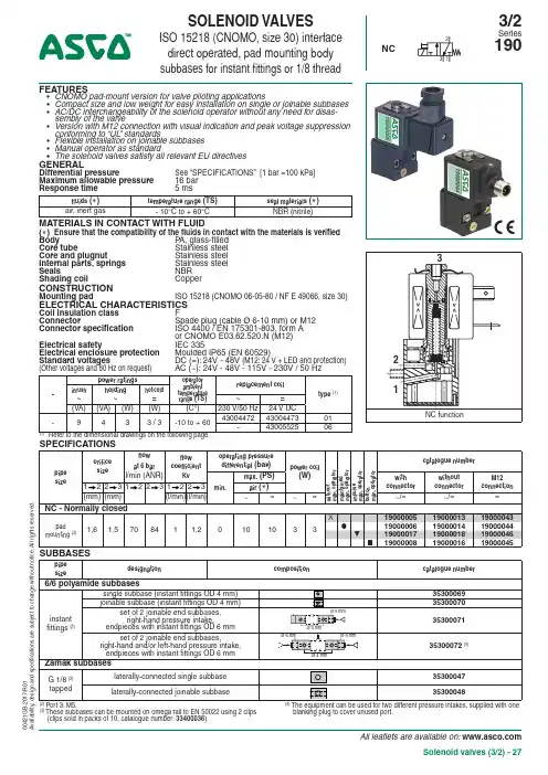
All leaflets are available on: Solenoid valves (3/2) - 27FEATURES• CNOMO pad-mount version for valve piloting applications• Compact size and low weight for easy installation on single or joinable subbases • AC/DC interchangeability of the solenoid operator without any need for disas-sembly of the valve• Version with M12 connection with visual indication and peak voltage suppression conforming to “UL ” standards• Flexible installation on joinable subbases • Manual operator as standard• The solenoid valves satisfy all relevant EU directivesGENERALDifferential pressureSee “SPECIFICATIONS” [1 bar =100 kPa]Maximum allowable pressure 16 bar Response time5 msfluids ( )temperature range (TS)seal materials ( )air, inert gas- 10°C to + 60°CNBR (nitrile)MATERIALS IN CONTACT WITH FLUID( ) Ensure that the compatibility of the fluids in contact with the materials is verified Body P A, glass-filled Core tube Stainless steel Core and plugnut Stainless steel Internal parts, springs Stainless steel Seals NBR Shading coil CopperCONSTRUCTIONMounting padISO 15218 (CNOMO 06-05-80 / NF E 49066, size 30)ELECTRICAL CHARACTERISTICSCoil insulation class F Connector Spade plug (cable Ø 6-10 mm) or M12 Connector specification ISO 4400 / EN 175301-803, form A or CNOMO E03.62.520.N (M12)Electrical safety IEC 335Electrical enclosure protection Moulded IP65 (EN 60529)Standard voltages DC (=): 24V - 48V (M12: 24 V + LED and protection) (Other voltages and 60 Hz on request) AC (~): 24V - 48V - 115V - 230V / 50 Hz-power ratings operator ambient temperature range (TS)replacement coil type (1)inrush~holding ~hot/cold =~=(VA)(VA)(W)(W)(C°)230 V/50 Hz 24 V DC -9433 / 3-10 to + 60430044724300447301-4300552506(1)Refer to the dimensional drawings on the following page.(3)T hese subbases can be mounted on omega rail to EN 50022 using 2 clips (clips sold in packs of 10, catalogue number: 33400036).blanking plug to cover unused port.SOLENOID VALVESISO 15218 (CNOMO, size 30) interface direct operated, pad mounting body subbases for instant fittings or 1/8 threadNC3/2Series 19000421G B -2017/R 01A v a i l a b i l i t y , d e s i g n a n d s p e c i fi c a t i o n s a r e s u b j e c t t o c h a n g e w i t h o u t n o t i c e . A l l r i g h t s r e s e r v e d .All leaflets are available on: 28 - Solenoid valves (3/2)OPTIONS• Explosionproof enclosures for use in zones 1/21-2/22, categories 2-3 to ATEX Directive 2014/34/EU (see “Explosionproof solenoids” section): Ex mb (PV ), PV19000005/6/17/8 / Potentially explosive atmospheres (SG ), zone 22• Straight M12 connector (IP67 protection with connector correctly installed): with 5 m cable: catalogue number 88130212• Right-angle M12 connector (IP67 protection with connector correctly installed), with 5 m cable: catalogue number 88130213• Catalogue number (without connector) + connector catalogue number (with integrated LED indicator and electrical protection ): 24 V (~/=), 88122603 - 48 V (~/=), 88122604 - 115 V (~), 88122605 - 230 V (~), 88122608• M5 flow control regulator to fit port 3, catalogue number: 34600380• Plug with visual indication and peak voltage suppression or with cable length of 2 m (see Solenoids, Coils & Accessories section)INSTALLATION• The solenoid valves can be mounted in any position without affecting operation • Mounting on single or joinable subbases• ATEX 2014/34/EU versions (options “SG” and “PV”) can be installed on single (all versions) or joinable zink diecast subbases • Pipe connections 1/8 have standard thread according to ISO 228/1•Installation/maintenance instructions are included with each valveORDERING EXAMPLES:19000006230V /50 Hz 1900004424V /DCvoltage basic numberoptionsSOLENOID VALVES SERIES 190DIMENSIONS (mm), WEIGHT(kg)TYPE 01- 06Spade plug /M12IEC 335 /EN 175301-803 (11 mm)E03.62.520.N, IP6519000005 to19000045TYPE 02Single instant fitting subbase PolyamideTYPE 04Single subbase Zamak35300047TYPE 03Joinable instant fitting subbase Polyamide 3530007035300071 (set of 2)TYPE 05Joinable subbase Zamak 35300048Right-hand pressure intake option or 2 different pres-sure intakes by procuring the set of two end subbases with endpieces (catalogue number: 35300072).When mounted on DIN rail, it is recommended to use a securing clip on the end subbases as well as on the central subbase.instant-fitting endpieces (catalogue number: 35300071 )2 locking U-piecesO-ringJoinable subbase (catalogue number: 35300070)PolarizerInstant-fitting endpiece(except M12 connection type 06)00421G B -2017/R 01A v a i l a b i l i t y , d e s i g n a n d s p e c i fi c a t i o n s a r e s u b j e c t t o c h a n g e w i t h o u t n o t i c e . A l l r i g h t s r e s e r v e d .1 Manual operator location2 Port 3: M5, depth 5,5 mm3 Mounting: two CM4 x 33,5 screws4 Instant-fitting connection for OD 4 mm tube5 Mounting: two dia. 3,5 mm securing holes, dia. 6,5 mm counter-bores, depth 3,5 mm6 Instant-fitting connection for OD 6 mm tube7 Mounting: two dia. 4,5 mm securing holes8 Adaptable clips9Subbase mounting hole, adapter。
分别介绍美国ASCO电磁阀的结构特点与工作原理以及安装一、简介美国ASCO电磁阀是一种用于掌控液体和气体流动的电掌控元件。
作为一种广泛应用的自动化设备,电磁阀广泛应用于各种工业领域,如石油、化工、航空、军事、水处理、制药、食品等领域。
在现代工业自动化系统中,ASCO电磁阀通常是起掌控作用的中央元件之一、二、结构特点美国ASCO电磁阀的结构包括导管、活塞、阀门和线圈。
其结构特点如下:1.导管——由高质量的铜或不锈钢制成,具有优越的耐用性和防腐性能;2.活塞——是电磁阀的核心部件,其功能在于隔断或通导流体管道;其通常由高强度的不锈钢材料制成,具有良好的抗腐蚀性和耐久性;3.阀门——也称作永磁核,由铜制成,并通过电磁力与活塞密封,防止流体漏出;4.线圈——紧要由高质量的铜线和里芯构成,其作用在于产生磁场,以掌控活塞的移动;三、工作原理美国ASCO电磁阀的工作原理是依靠电信号驱动,通过电磁铁产生的磁场来掌控阀门的状态,从而达到管道中的流体掌控。
实在来说,当电磁铁通电时,纵向线圈内电流产生磁力,使得阀门铁芯处于吸合状态,此时活塞和阀门吻合,流体被阀门和活塞隔开,阀门关闭状态被保持。
相反,当电磁铁断电时,吸合力减弱,阀门闭合弹簧将其关闭,此时,活塞会脱离阀门,流体开始流动。
美国ASCO电磁阀可以依据需要单独安装,也可以与其他设备一起搭配使用。
在不同的工业场合,需要设计不同的电磁阀掌控方案,以实现掌控和调整流量等功能。
四、安装美国ASCO电磁阀的安装应当遵守以下基本要求:1.电磁阀应当安装在水平或者垂直管道上;2.安装时应当确保流体的进出方向与电磁阀的正负极相匹配;3.安装前应当清洗管道,并确保管道内部没有异物或者污垢;4.安装时应当使用密封垫等密封材料,以防止漏水;5.安装后应当进行试运行和调试操作,确保电磁阀的工作正常。
除此之外,当需要进行维护时,需要通过拆除连接螺栓和管道来拆卸电磁阀。
在拆卸时,应当遵奉并服从相应的拆卸步骤和要求,以保证拆卸的正常进行,并防止损坏电磁阀。
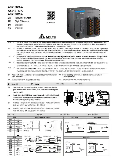
AS218RX-A AS218TX-AAS218PX-A5014086002EN Instruction Sheet TR Bilgi DökümaniTW 安裝說明 CN安装说明ENThis is an OPEN TYPE module and therefore should be installed in an enclosure free of airborne dust, humidity, electric shock andvibration. The enclosure should prevent non-maintenance staff from operating the device (e.g. key or specific tools are required for operating the enclosure) in case danger and damage on the device may occur.FRCeci est un module ouvert et il doit donc être installé dans un coffret à l’abri des poussières, des vibrations et ne pas être exposé auxchocs électriques. Le boitier ou l’armoire doit éviter toute action d’un personnel autre que celui affecté à la maintenance de l’appareil (par exemple, clefs, outils spécifiques pour l’ouverture du coffret), ceci afin d’éviter tout accident corporel ou endommagement du produit).TRBu ürün AÇIK TİP bir modül olup toz, rutubet, elektrik şoku ve titreşimden uzak kapalı yerlerde muhafaza edilmelidir. Yanlış kullanımsonucu ürünün zarar görmesini önlemek için yetkili olmayan kişiler tarafından ürüne müdahale edilmesini önleyecek koruyucu önlemler alınmalıdır. (Ürünün bulunduğu panoya kilit konulması gibi).TW本機為開放型(OPEN TYPE )機種,因此使用者使用本機時,必須將之安裝於具防塵、防潮及免於電擊∕衝擊意外之外殼配線箱內。
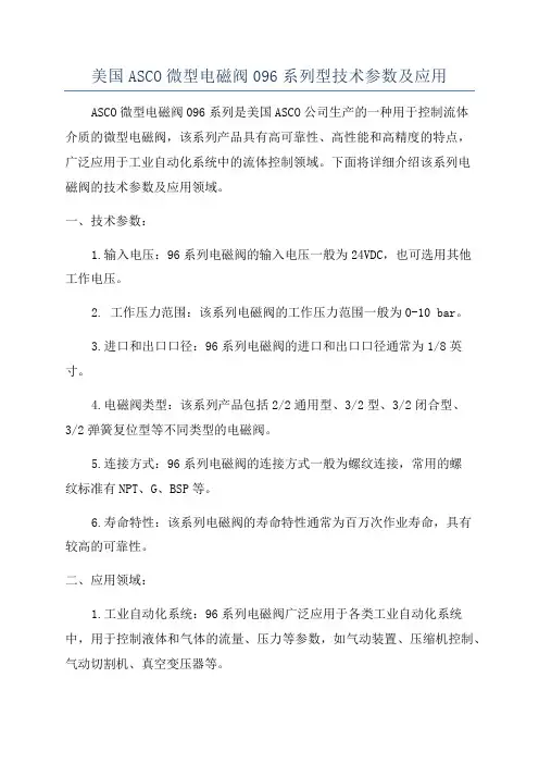
美国ASCO微型电磁阀096系列型技术参数及应用ASCO微型电磁阀096系列是美国ASCO公司生产的一种用于控制流体介质的微型电磁阀,该系列产品具有高可靠性、高性能和高精度的特点,广泛应用于工业自动化系统中的流体控制领域。
下面将详细介绍该系列电磁阀的技术参数及应用领域。
一、技术参数:1.输入电压:96系列电磁阀的输入电压一般为24VDC,也可选用其他工作电压。
2. 工作压力范围:该系列电磁阀的工作压力范围一般为0-10 bar。
3.进口和出口口径:96系列电磁阀的进口和出口口径通常为1/8英寸。
4.电磁阀类型:该系列产品包括2/2通用型、3/2型、3/2闭合型、3/2弹簧复位型等不同类型的电磁阀。
5.连接方式:96系列电磁阀的连接方式一般为螺纹连接,常用的螺纹标准有NPT、G、BSP等。
6.寿命特性:该系列电磁阀的寿命特性通常为百万次作业寿命,具有较高的可靠性。
二、应用领域:1.工业自动化系统:96系列电磁阀广泛应用于各类工业自动化系统中,用于控制液体和气体的流量、压力等参数,如气动装置、压缩机控制、气动切割机、真空变压器等。
2.仪器仪表:由于96系列电磁阀体积小巧、结构紧凑,因此在仪器仪表领域应用十分广泛。
例如,在实验设备中用于控制药液的进出、温度和压力控制等。
3.医疗设备:96系列电磁阀在医疗设备中也有较多的应用,如呼吸机、输液泵、血液分析仪等。
这些设备对电磁阀的控制要求较高,因此选择ASCO微型电磁阀096系列可以满足其高精度控制的需求。
4.生物工程:在生物工程领域,96系列电磁阀常用于反应釜、生物发酵罐等设备中,用于控制液体介质的流动和分配。
5.环境监测:在环境监测领域,96系列电磁阀常用于大气采样设备、废气处理设备等,用于控制气体的流动和采样。
总结:ASCO微型电磁阀096系列是一款具有高可靠性、高性能和高精度的电磁阀产品。
其技术参数包括输入电压、工作压力范围、进口和出口口径、电磁阀类型、连接方式和寿命特性等。
2011-9-817:30:29ASCO-JOUCOMATIC电磁阀使用说明ASCO-JOUCOMA TIC电磁阀它是一种直动和先导式相结合的原理,当入口与出口没有压差时,通电后,电磁力直接把先导小阀和主阀关闭件依次向上提起,阀门打开。
当入口与出口达到启动压差时,通电后,电磁力先导小阀,主阀下腔压力上升,上腔压力下降,从而利用压差把主阀向上推开;断电时,先导阀利用弹簧力或介质压力推动关闭件,向下移动,使关闭。
ASCO-JOUCOMA TIC电磁阀特点:在零压差或真空、高压时亦能可动作,但功率较大,要求必须水平安装。
先导式:原理:通电时,电磁力把先导孔打开,上腔室压力迅速下降,在关闭件周围形成上低下高的压差,流体压力推动关闭件向上移动,打开;断电时,弹簧力把先导孔关闭,入口压力通过旁通孔迅速腔室在关阀件周围形成下低上高的压差,流体压力推动关闭件向下移动,关闭。
ASCO-JOUCOMA TIC电磁阀特点:流体压力范围上限较高,可任意安装(需定制)但必须满足流体压差条件ASCO-JOUCOMATIC在电磁阀和机械阀方面,提代了一个广泛的选择,其中流体可以是易燃、易爆介质或腐蚀性介质。
压力可达到150巴,温度可以从-50到300。
口径主要有从1/8英寸到6英寸,操作形式有常闭型,常开型和通用型的2,3,4,5通电磁阀。
防爆电磁阀通用电磁阀热水和蒸汽电磁阀用于真空系统的磁磁阀用于燃烧系统的电磁阀(介质是油气和燃料油)各种工程用电磁阀NAMUR电磁阀用于除尘系统的电磁阀用于低温系统的电磁阀燃料分配电磁阀(用于各种油料加油机)防水锤设计的缓慢关闭式电磁阀比例电磁阀医药和分析领域用电磁阀用于核电厂的电磁阀美国ASCO(JOUCOMATIC)公司产品系列简介系列型号结构名称管径压差8030系列sc※030系列直动式低压电磁阀3/8-3/40—2—15psi8210/8230系列sc※系列先导式电磁阀3/8-30--150,5--300psi8262/8263系列sc※262/263系列直动式低压电磁阀1/8-3/80-26-220系列sc※220系列热水蒸气电磁阀1/4-21/20-100-150,5-1008260系列sc※260系列制冷液态CO2专用电磁阀1/8-1/20-100,5-2008215系列sc※215系列低压真空白电磁阀1/4-3/40-15,25-10↑-9mmHgsc ※215系列高压电磁阀1/4-3/40.7-100bar8353系列sc※215系列高流量脉冲(除尘)电磁阀3/4-35-125psiMFQ系列高频长寿电磁阀1-122.5Mpa快速排污电磁阀4-12P1.0Mpa015/025系列sc※215系列受动复位电磁阀3/4--2.55-250psi300/320系列sc※215系列直动式通用电磁阀1/8-1/2300Psi三通,四通电磁阀1/4-3/8125psi8316系列sc※215系列先导式三通电磁阀3/8-11/2-10-250psi401系列sc※215系列滑动式电磁阀1/8-1/20-150psi317/321系列sc※215系列三通先导快排电磁阀1/8-3/80-200psi307/308/310系列sc※215系列三通手动复位电磁阀1/4-10-250psi8340系列sc※215系列四通直动(空气)电磁阀1/8-3/80-250psi8300系列sc※215系列3,4通本安电磁阀(可受动复位)1/4-10-250psi165系列2/2sc※215系列气控阀1/2-216-25-40barE390系列sc※215系列三通1/2-210,1640bar166系列sc※215系列三通1/2-2-41.5-10bar340系列sc※215系列四通1/40-9bar551系列sc※215系列五通11.5-10bar551A系列sc※215系列五通1/42-10bar是用来控制流体的自动化基础元件,属于执行器;并不限于液压,气动。

I&M V 9629 R6 Solenoid Valves used in SafetyInstrumented SystemsASCO Valves ®Page 1 of 7Table of Contents1 I ntroduction (3)1.1 Terms and Abbreviations (3)1.2 Acronyms (3)2 Designing a Safety Instrumented Function using an ASCO Solenoid Valve (4)2.1 Safety Function (4)2.2 Environmental limits (4)2.3 Application limits (4)2.4 Design Verification (4)2.5 SIL Capability (5)2.5.1 Systematic Integrity (5)2.5.2 Random Integrity (5)3 Installation and Commissioning (5)3.1 Installation (5)3.2 Response Time (6)4 Operation and Maintenance (6)4.1 Proof test without automatic testing (6)4.2 Proof test with automatic partial valve stroke testing (6)4.3 Repair and replacement (7)4.4 ASCO Notification (7)5 ASCO Solenoid Pilot Valves Covered (7)6 Status of the document (7)6.1 Releases (7)1 IntroductionThis Operating Manual provides the necessary information to design, install, verify and maintain a Safety Instrumented Function (SIF) utilizing an ASCO Solenoid Valve. This manual provides necessary requirements for meeting the IEC 61508 or IEC 61511 functional safety standards.1.1 Terms and Abbreviations• Process Valve Any valve that is used to control the flow of media being used in a process.For the purpose of this document, this is usually a 2-way valve whosemovement is being controlled by an actuator and pilot valve.• Pilot Valve A 3-way or 4-way valve that is used to send or remove pressurized mediato and from an actuator for the opening and closing of a process valve.• Direct Acting Refers to a solenoid valves main orifice that is opened and closed as adirect result of the solenoid valves electromagnetic movement when thecoil is energized and de-energized.• Indirect Acting Refers to a solenoid valve’s main orifice that is opened and closed as aresult of fluid flow being directed from the electromagnetic 3-way solenoidpilot.• Safety Freedom from unacceptable risk of harm• Functional Safety The ability of a system to carry out the actions necessary to achieve or tomaintain a defined safe state for the equipment / machinery / plant /apparatus under control of the system• Basic Safety The equipment must be designed and manufactured such that it protectsagainst risk of damage to persons by electrical shock and other hazardsand against resulting fire and explosion. The protection must be effectiveunder all conditions of the nominal operation and under single faultcondition• Safety Assessment The investigation to arrive at a judgment - based on evidence - of thesafety achieved by safety-related systems• Fail-Safe State The state where the solenoid is de-energized and its return spring holdsthe pilot in the closed position.• Fail Safe Failure that causes the valve to go to the defined fail-safe state without ademand from the process.• Fail Dangerous Failure that does not respond to a demand from the process (i.e. beingunable to go to the defined fail-safe state).• Fail Dangerous Undetected (DU) Failure that is dangerous and that is not being diagnosed byautomatic stroke testing.• Fail Dangerous Detected (DD) Failure that is dangerous but is detected by automatic stroke testing.• Fail No Effect Failure of a component that is part of the safety function but that has noeffect on the safety function.• Low Demand Mode Mode, where the frequency of demands for operation made on a safety-related system is no greater than twice the proof test frequency.1.2 Acronyms• FMEDA Failure Modes, Effects and Diagnostic Analysis• HFT Hardware Fault Tolerance• MOC Management of Change: These are specific procedures often done whenperforming any work activities in compliance with government regulatoryauthorities.• PFD AVG Average Probability of Failure on Demand• SFF Safe Failure Fraction, the fraction of the overall failure rate of a device thatresults in either a safe fault or a diagnosed unsafe fault.• SIF Safety Instrumented Function, a set of equipment intended to reduce therisk due to a specific hazard (a safety loop).• SIL Safety Integrity Level, discrete level (one out of a possible four) forspecifying the safety integrity requirements of the safety functions to beallocated to the E/E/PE safety-related systems where Safety Integrity Level4 has the highest level of safety integrity and Safety Integrity Level 1 hasthe lowest.• SIS Safety Instrumented System – Implementation of one or more SafetyInstrumented Functions. A SIS is composed of any combination ofsensor(s), logic solver(s), and final element(s).2 D esigning a Safety Instrumented Function (SIF) using an ASCOSolenoid Valve2.1 Safety FunctionWhen de-energized, the ASCO Solenoid Pilot Valve moves to its fail-safe position. Depending on the solenoid specified Normally Closed (NC) or Normally Open (NO), the valve will supply the fluid media or vent the fluid media depending on the piping of the installation. Please note that the solenoid pilot valve must be piped to the actuator in accordance with the manufacturer’s recommendations and allowable desired function.The valve is intended to be part of final element subsystem as defined per IEC 61508 and the achieved SIL level of the designed function must be verified by the designer.2.2 Environmental limitsThe environmental limits of each solenoid are specified in the products respective catalog and Installation & Maintenance Instructions. The designer of a SIF must check that the product is rated for use within the expected environmental limits.2.3 Application limitsThe application limits of an ASCO Solenoid are specified in the products respective catalog and Installation & Maintenance Instructions. It is especially important that the designer check for material compatibility considering on-site chemical contaminants and air supply conditions. If the solenoid valve is used outside of the application limits or with incompatible materials, the reliability data provided becomes invalid.2.4 Design Verification• A detailed Failure Mode, Effects, and Diagnostics Analysis (FMEDA) report is available from ASCO.This report details all failure rates and failure modes as well as the expected lifetime.•The achieved Safety Integrity Level (SIL) of an entire Safety Instrumented Function (SIF) design must be verified by the designer via a calculation of PFD avg considering redundant architectures, proof test interval, proof test effectiveness, any automatic diagnostics, average repair time and the specific failure rates of all products included in the SIF. Each subsystem must be checked to assure compliance with minimum hardware fault tolerance (HFT) requirements. The Exida exSILentia tool is recommended for this work.•When using an ASCO Solenoid in a redundant configuration, a common cause factor of 5% should be included in safety integrity calculations.•The failure rate data listed the FMEDA report is only valid for the useful life time of an ASCO Solenoid.The failure rates will increase sometime after this time period. Reliability calculations based on the data listed in the FMEDA report for mission times beyond the lifetime may yield results that are too optimistic, i.e. the calculated Safety Integrity Level will not be achieved.2.5 SIL Capability2.5.1 Systematic IntegrityThe product has met manufacturer design process requirements of Safety Integrity Level (SIL) 3. These are intended to achieve sufficient integrity against systematic errors of design by the manufacturer. A Safety Instrumented Function (SIF) designed with this product must not be used at a SIL level higher than the statement without “prior use” justification by end user or diverse technology redundancy in the design.2.5.2 Random IntegrityThe solenoid valve is a Type A Device. Therefore when used the only component in a final element subassembly, a design can meet SIL 3 @ HFT=1 and SIL 2 @ HFT=0.When the final element assembly consists of many components (solenoid valve, quick exhaust valve, actuator, isolation valve, etc.) the SIL must be verified for the entire assembly using failure rates from all components. This analysis must account for any hardware fault tolerance and architecture constraints.3 Installation and Commissioning3.1 Installation•The ASCO Solenoid valve must be installed per standard installation practices outlined in the Installation Manual.•The environment must be checked to verify that environmental conditions do not exceed the ratings.•The ASCO Solenoid must be accessible for physical inspection.•Instrument Air Filtration: These solenoids are intended for use on clean, dry air or inert gas filtered to50 microns or better. To prevent freezing, the dew point of the media should be at least 18°F(10°C)below the minimum temperature to which any portion of the clean air or gas system could be exposed.Instrument air in compliance with ANSI/ISA Standard S7.3-1975 (R1981) exceeds the above requirements and is, therefore, an acceptable medium for these valves.• It is the operator’s responsibility to only use design options such as latches, when it is safe to do so.• Typical 3-way pilot valve piping configurations:a. 1 out-of 1 – This is the most common pilot valve configuration used.b. 2 out-of 2 – This is commonly used for high availability applications. In the case that onesolenoid valve was to spuriously trip, the second solenoid still maintains the position of theactuator/process valve at its operating state. Both solenoids must close in order to shift theactuator/process valve to its non-operating state.3.2 Response TimeThe response time of a solenoid pilot valve will vary by design. The factors that affect response time are pilot valve orifice size, operating pressure, size of actuator, torque required to open and close process valve, and distance between pilot valve and actuator. It is the responsibility of the end user to use a pilot valve that delivers the correct opening and closing time of the process valve required for the application.4 Operation and Maintenance4.1 Proof test without automatic testingThe objective of proof testing is to detect failures within an ASCO Solenoid that are not detected by any automatic diagnostics of the system. Of main concern are undetected failures that prevent the safety instrumented function from performing its intended function.The frequency of proof testing, or the proof test interval, is to be determined in reliability calculations for the safety instrumented functions for which an ASCO Solenoid is applied. The proof tests must be performed more frequently than or as frequently as specified in the calculation in order to maintain the required safety integrity of the safety instrumented function.The following proof test is recommended. Any failures that are detected and that compromise functional safety should be reported to ASCO.Table 11Bypass the safety PLC or take other appropriate action to avoid a false trip, following company Management of Change (MOC) procedures2Inspect the external parts of the solenoid valve for dirty or clogged ports and other physical damage. Do not attempt disassembly of the valve.the 3De-energize the solenoid coil and observe that the actuator and valve move. Energize solenoid after a small movement of the valve.4Inspect the solenoid for dirt, corrosion or excessive moisture. Clean if necessary and take corrective action to properly clean the air supply. This is done to avoid incipient failures due todirty air.5Record a n y failures i n your c o m p a n y’s S I F i n s p e c t i o n d a t a b a s e. Restore the loop t o full operation.6Remove the bypass from the safety PLC or otherwise restore normal operationThis test will detect approximately 99% of possible DU failures in the solenoid (Proof Test Coverage).The person(s) performing the proof test of an ASCO Solenoid should be trained in SIS operations, including bypass procedures, solenoid maintenance and company Management of Change procedures. No special tools are required.4.2 Proof test with automatic partial valve stroke testingAn automatic partial valve stroke testing scheme that performs a full stroke of the solenoid valve and measures valve movement timing will detect most potentially dangerous failure modes. It is recommended that a physical inspection (Step 2 from Table 1) be performed on a periodic basis with the time interval determined by plant conditions. Maximum inspection interval is five years but an annual inspection is recommended.4.3 Repair and replacementAccording to section 7.4.7.4 of IEC 61508-2 a useful lifetime based on experience, should be assumed. General field knowledge suggests that most solenoid valves have a useful life of 3 to 10 years, but may be longer depending on the valve series and other factors.It is the responsibility of the end user to establish a preventative maintenance process to replace all solenoids before the end of the useful life.4.4 ASCO NotificationAny failures that are detected and that compromise functional safety should be reported to ASCO Valve. Please contact ASCO customer service.5 ASCO Solenoid Pilot Valves CoveredSelect ASCO valves from the following series have been evaluated per IEC 61508 parts 1 and 2 and covered under this document:∙8314 Series - 3-Way Direct Acting Pilot Valves∙8320 Series - 3-Way Direct Acting Pilot Valves∙8316 Series - 3-Way Indirect Acting Pilot Valves∙551, 552, 553 Series - 3 and 4-Way Indirect Acting Pilot Valves∙8317, 8320, 8321 Series - 3-Way Harsh Environment Pilot Valves∙327/8327 Series - 3-Way Direct Acting Pilot Valves.∙126 Series - 3-Way Direct Acting Pilot Valves.∙8317 Series – 3-Way Piloting Quick Exhaust valve∙307 Series - 3-Way Direct Acting Pilot Valves∙364 Series – 3-Way Spool Valves∙362/562 Series – 3-Way and 4-Way Spool Valves6 Status of the document6.1 ReleasesRevision: GECN Number: 264756Release status: V9629 Initial Release on 02/18/11。
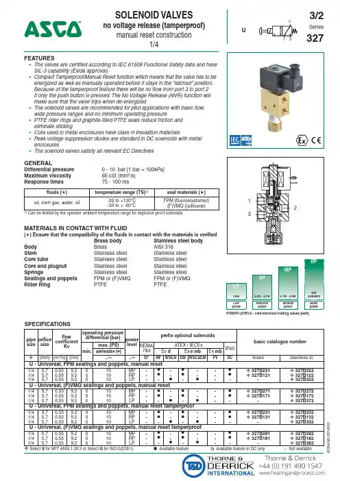
15/R 03USOLENOID VALVESno voltage release (tamperproof)manual reset construction1/4213FEATURES• The valves are certified according to IEC 61508 Functional Safety data and have SIL-3 capability (Exida approval)• Compact Tamperproof/Manual Reset function which means that the valve has to be energized as well as manually operated before it stays in the "latched" position. Because of the tamperproof feature there will be no flow from port 3 to port 2 if only the push button is pressed. The No Voltage Release (NVR) function will make sure that the valve trips when de-energized• The solenoid valves are recommended for pilot applications with basic flow, wide pressure ranges and no minimum operating pressure• PTFE rider rings and graphite-filled PTFE seals reduce friction and eliminate sticking• Coils used in metal enclosures have class H insulation materials• Peak voltage suppression diodes are standard in DC solenoids with metal enclosures• The solenoid valves satisfy all relevant EC DirectivesGENERALDifferential pressure 0 - 10 bar [1 bar = 100kPa]Maximum viscosity 65 cSt (mm 2/s)Response times75 - 100 msfluids (✶)temperature range (TS)(1)seal materials (✶)air, inert gas, water, oil-20 to +120°C -50 to + 60°CFPM (fluoroelastomer)(F)VMQ ((sillicone)(1)Can be limited by the operator ambient temperature range for explosion proof solenoidsMATERIALS IN CONTACT WITH FLUID(✶) Ensure that the compatibility of the fluids in contact with the materials is verifiedBrass bodyStainless steel body Body Brass AISI 316Stem Stainless steel Stainless steel Core tube Stainless steel Stainless steel Core and plugnut Stainless steel Stainless steel Springs Stainless steel Stainless steel Sealings and poppets FPM or (F)VMQFPM or (F)VMQ Rider Ring PTFE PTFEBPMPRPLP1,8W 3,6W - 3,7W 5,7W - 5,8W Not Available Low powerReduced powerMedium powerBasic powerPOWER LEVELS - cold electrical holding values (watt)SPECIFICATIONSpipe size orificesizeflowcoefficientKv operating pressuredifferential (bar)powerlevel prefix optional solenoidsbasic catalogue number min.max. (PS)NEMA 7&9ATEX / IECExIP65air/water (✶)Ex d Ex e mb Ex mb (mm)(m 3/h)(l/m)~/=~/=EF NF WSCR EM WSCREM PV SC brass stainless st.U - Universal, FPM sealings and poppets, manual reset1/45,70,559,2010MP -●-●--● 327B221 327B2221/45,70,559,2010RP -●-●--● 327B121327B1221/45,70,559,2010LP --●-●--- 327B322U - Universal, (F)VMQ sealings and poppets, manual reset1/45,70,559,2010MP -●-●--● 327B271 327B2721/45,70,559,2010RP -●-●--● 327B171327B1721/45,70,559,2010LP --●-●--- 327B372U - Universal, FPM sealings and poppets, manual reset tamperproof1/45,70,559,2010MP -●-●--● 327B231 327B2321/45,70,559,2010RP -●-●--● 327B131327B1321/45,70,559,2010LP --●-●--- 327B332U - Universal, (F)VMQ sealings and poppets, manual reset tamperproof1/45,70,559,2010MP -●-●--● 327B281 327B2823/2Series32715/R 03PRODUCT SELECTION GUIDESTEP 1Select basic cataloguenumber,including pipe thread indentification letter. Refer to the specifications table on page 1.Example: 8327B221STEP 2Select prefix (combination). Refer to the specifications table on page 1 and the prefix table on page 2, respect the indicated power level.Example: NFSTEP 3Select suffix (combination) if required. Refer to the suffix table on page 2, respect the indicated power level.Example: COSTEP 4Select voltage. Refer to standard voltages on page 3.Example: 230V / 50/60 Hz STEP 5Final catalogue / ordering number. Example:NF 8327B221 CO 230V / 50/60 HzPREFIX TABLEprefix description power level 1234567LP RP MP BPE M Waterproof IP66/67 - Metal enclosure (EN/IEC 60079-7,-18 and -31)*-●●-E T Threaded conduit/hole (M20 x 1,5)-●●-N F Flameproof - Aluminium (EN/IEC 60079-1, 60079-31)*-●●-S C Solenoid with spade plug connector (EN/IEC 60730)-●●-W P Waterproof IP67 - Metal enclosure -●●-W S Waterproof IP67 - 316 SS enclosure -●●-W S C R Flameproof 316L SS (EN/IEC 60079-0+1+31)*●---W S C R E M Increased Safety / Encapsulated 316L SS (EN/IEC 60079-0+7+18+31)*●---W S E M Waterproof IP66/67 - 316 SS enclosure (EN/IEC 60079-7,-18 and -31)*-●●-WS N F Flameproof - 316L SS (EN/IEC 60079-1, 60079-31)*-●●-T Threaded conduit (1/2" NPT)-●●-X Other special constructions-●●-SUFFIX TABLEsuffix descriptionpower level 12345LP RP MP BPN V FPM (fluoroelastomer) and parts cleaned for oxygen service -●●-C OEpoxy coating on all external surfaces-●●-● Available feature ❍ Available feature in DC only- Not available * A TEX/IECEx valves using these solenoids are approved according to EN 13463-1 (non electrical)(1)Functional Safety certification is not applicable with this featureOPTIONS & ACCESSORIEScatalogue number spare part kit no.(2)mounting bracket ~ / =SC 327B121C132251⏹SC 327B122C132251⏹SC 327B131C132253⏹SC 327B132C132253⏹SC 327B171C117646⏹SC 327B172C117646⏹SC 327B181C117647⏹SC 327B182C117647⏹SC 327B221C132251⏹SC 327B222C132251⏹SC 327B231C132253⏹SC 327B232C132253⏹SC 327B271C117648⏹SC 327B272C117648⏹SC 327B281C117649⏹SC 327B282C117649⏹Select 8 for NPT ANSI 1.20.3 or select G for ISO G(228/1)(2)Standard prefixes/suffixes are also applicable to kits ⏹ Mounting holes in bodyORDERING EXAMPLES VALVES:SC 8327B 12124V /DC WSEMT G 327B 122CO 24V /DC NFET G 327B 221230V /50/60 HzWSEMG 327B 12224V /DC NF 8327B 231CO 24V /DC WS G 327B 121CO 24V /DC EM8327B 221230V /50/60 Hzprefix pipe thread voltagebasic numbersuffixORDERING EXAMPLES KITS:C132251(3)NF C117646WSEM C132251prefixsuffixbasic number(3)Basic kit number applies to SC coil construction15/R 03EXPLANATION OF TEMPERATURE RANGES OF SOLENOID VALVESValve temperature rangeThe valve temperature range (TS) is determined by the selected seal material, the temperature range for proper operation of the valve and sometimes by the fluid (e.g. steam)Operator ambient temperature range The operator ambient temperature range is determined by the selected power level and the safety codeTotal temperature rangeThe temperature range of the complete solenoid valve is determined by the limitations of both temperature ranges aboveELECTRICAL CHARACTERISTICSCoil insulation class HElectrical safety IEC 335Standard voltages DC (=) 24V - 48V; Allowable voltage variation ± 10%AC (~) 24V - 48V - 115V - 230V/50/60Hz; Other voltages are available on requestprefix optionpower ratingsoperator ambienttemperature range safety codeelectrical enclosure protection (EN 60529)replacement coil / kit type (2)inrush holding hot/cold ~~=~=(VA )(VA )(W )(W ) (C°)(1)230V/50/60 Hz 24V/DC Medium Power (MP)SC5,85,85,85,2/5,7-40 to +90EN 60730IP65, moulded 400924-297400923-44201WP/WS 5,85,85,85,2/5,7-40 to +90EN 60730IP67, steel /SS 400921-297400914-44202NF/WSNF 5,85,85,85,2/5,7-60 to +60/75/90II2G Ex d IIC Gb T6/T5/T4, II2D Ex tb IIIC Db IP66/67, alu./SS 400921-297400914-44203EM/WSEM 5,85,85,85,2/5,7-40 to +40/75II2G Ex e mb IIC Gb T5/T4, II2D Ex tb IIIC Db IP66/67, steel /SS 400921-297400914-44202Reduced Power (RP)(3)SC3,73,73,73,2/3,6-40 to +60EN 60730IP65, moulded - (3)400923-04201WP/WS 3,73,73,73,2/3,6-40 to +60EN 60730IP67, steel /SS - (3)400914-24202NF/WSNF 3,73,73,73,2/3,6-60 to +60II2G Ex d IIC Gb T6, II2D Ex tb IIIC Db IP66/67, alu./SS - (3)400914-24203EM/WSEM 3,73,73,73,2/3,6-40 to +40/60II2G Ex e mb IIC Gb T6/T5, II2D Ex tb IIIC Db IP66/67, steel /SS - (3)400914-24202Low Power (LP)(3)WSCR 1,851,851,851,5/1,8-60 to +60II2G Ex d IIC Gb T6, II2D Ex t IIIC Db IP66/67, SS - (3)400961-54204WSCREM1,851,851,851,5/1,8-60 to +60II2G Ex e mb IIC Gb T6, II2D Ex tb IIIC DbIP66/67, SS- (3)400961-54204(1) Temperature range can be limited by sealings (2)Refer to the dimensional drawings on page 4(3)AC (~) limited to 127V/50/60Hz or 125V/DC - Not availableELECTRICAL CONNECTIONSprefix connectionSCSpade plug connector with cable gland EN175301-803A (ISO 4400) for cables with an outer dia-meter from 6 to 10 mmWP , WS, EM, WSEM M20 cable gland for cables with an outer diameter from 7 to 12 mm. With an internal and external facility for an earthing or bonding conductorNF , WSNF , WSCR 1/2" NPT threaded cable entry. Enclosures are supplied without cable glandWSCREM M20 x 1,5 316 SS cable gland for cables with an outer diameter from 7,2 to 11,7 mm.NFET, WSNFET M20 x 1,5 threaded cable entry. Enclosures are supplied without cable glandADDITIONAL OPTIONS●Ex mb/mD (prefix "PV") solenoid can be supplied with various cable lengths ●Compliance with "UL", "CSA" and other local approvals available on request ●Manual Reset constructions suitable for -40°C are available on requestINSTALLATION●Multi language installation/maintenance instructions are included with each valve ●The solenoid valves can be mounted in any position without affecting operation ●The mounting holes are provided in the valve body●Threaded pipe connection identifier is 8 = NPT (ANSI 1.20.3); G = G (ISO 228/1)●Declarations of conformity are available on request●Ex e mb Prefix "EM" execution: solenoid enclosure has a cable gland with integral strain relief for cables with an o.d.from 7 to 12 mm and is provided with an internal and external connection facility for an earthing or bonding conductor ●Ex d Prefix "NF/WSNF" enclosure is provided with a 1/2" NPT threaded entry hole, M20 x 1,5 (prefix "ET") is optional Both are supplied without cable gland●All DC solenoids with metal enclosure are provided with switch-off peak voltage suppression diodes15/R 03DIMENSIONS (mm), WEIGHT (kg)TYPE 01:TYPE 02:Epoxy mouldedSC: IEC 335 / ISO 4400Metal, epoxy coated / AISI 316 SS WP / WS: IEC 335EM / WSEM: EN/IEC 60079-7+18+31327B121 / B122 / B131 / B132 / B221 / B222 / B231 / B232327B121 / B122 / B131 / B132 / B221 / B222 / B231 / B232TYPE 03:TYPE 04:Aluminium, epoxy coated / AISI 316L SS NF / WSNF: EN/IEC 60079-1, 60079-31AISI 316L SS WSCR : EN/IEC 60079-0, 60079-1, 60079-31WSCREM : E N/IEC 60079-0, 60079-7, 60079-18,EN/IEC 60079-31B121 / B122 / 327B131 / B132 / B221 / B222 / B231 / B232327B322 / B332 / B372 / B382ABCØ5,512232741DGJKELMDIMENSIONS (mm), WEIGHT (kg)type prefix/option power level A B C D E F G H J K L M N weight 01SCMP/RP 5030249814995915633552786-1,30 kg 02WP , WS, EM, WSEM MP/RP 773024101158-120-81552789-1,30 kg 03NF , WSNFMP/RP 973024125176-102-545527113882,70 kg 04WSCR, WSCREMLP923024127178-116-755527115-3,10 kg15/R 03EXHAUST PROTECTOR ORDER NUMBERS¼ISO 228/1brass/nickelB-MV110014NPT B-PV110014ISO 228/1stainless steelB-VX110014NPTB-PV110014EXHAUST PROTECTOR213SECTIONAL DRAWINGExecution : Reduced Power Tamperproof-G B -- A v a i l a b i l i t y , d e s i g n a n d s p e c i fic a t i o n s a r e s u b j e c t t o c h a n g e w i t h o u t n o t i c e . A l l r i g h t s r e s e r v e d .15/R 03。
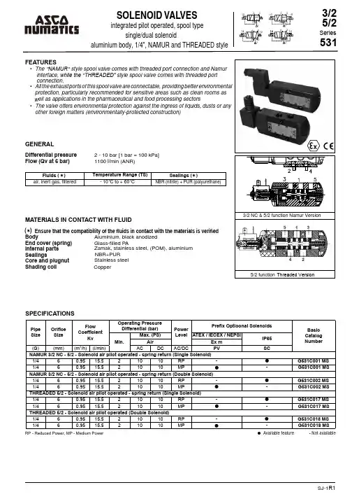
SJ-1R1Flow (Qv at 6 bar)1100 l/min (ANR)Fl uids ( ) Temperature Range (TS)Sealings ( )air, inert gas, fi ltered- 10°C to + 60°CNBR (nitrile) + PUR (polyurethane)MATERIALS IN CONTACT WITH FLUIDBody Aluminium, black anodized End cover (spring) Glass-fi lled P Alnternal partsZamak, stainless steel, (POM), aluminium Stainless steel Core and plugnutSealingsNBR+PUR Shading coil CopperSPECIFICATIONS● Available feature- Not available( ) RP - Reduced Power, MP - Medium Power•••• Ensure that the compatibility of the fluids in contact with the materials is verifiedPipe Size Orifice Size FlowCoefficientKvOperating PressureDifferential (bar)PowerLevel Prefix Optioonal SolenoidsBasic Catalog NumberMin.Max. (PS)ATEX / IECEX / NEPSIIP65Air Ex m(G)(mm)(m 3/h)(l/min)AC DC AC/DC PV SC NAMUR 3/2 NC - 5/2 - Solenoid air pilot operated - spring return (Single Solenoid)1/460.9515.521010RP -G531C001 MS 1/460.9515.521010MP -G531C001 MS NAMUR 3/2 NC - 5/2 - Solenoid air pilot operated - spring return (Double Solenoid)1/460.9515.521010RP -G531C002 MS 1/460.9515.521010MP -G531C002 MS THREADED 5/2 - Solenoid air pilot operated - spring return (Single Solenoid)1/460.9515.521010RP -G531C017 MS 1/460.9515.521010MP -G531C017 MS THREADED 5/2 - Solenoid air pilot operated (Double Solenoid)1/460.9515.521010RP -G531C018 MS 1/460.9515.521010MP -G531C018 MS••••ORDERING EXAMPLES:SERIES 531EXPLANATION OF TEMPERATURE RANGES OF SOLENOID VALVESValve temperature range The valve temperature range is determined by the selected seal material, the temperature range for proper operation of the valve and sometimes by the fluid ( e.g. steam )Operator ambient temperature rangeThe operator ambient temperature range is determined by the selected power level ( LP, RP, MP or BP ) and the ATEX safety codeTotal temperature rangeThe temperature range of the complete solenoid valvle is determined by the limitations of both temperature range aboveELECTRICAL CHARACTERISTICSCoil insulation class FElectrical safety IEC 335Standard voltages DC 24V - 48VAC 24V - 48V - 115V - 230V/50Hz(Other voltages and 60 Hz available on request)SJ-2R1ADDITIONAL OPTIONSELECTRICAL CONNECTIONSPrefix Connection SC Spade plug connector with cable gland DIN 43650, 11mm, industry standard B, for cables with an outer diameter from 6 to 8 mm (Type 01 / 03) PVMoulded - in cable, standard length 2m (Type 02 / 04)・Other pipe threads are available on request・Plug with visual indication and peak voltage suppression or with cable length of 2m, SC prefix only (Consult ASCO NUMATICS Ofices) ・Moulded-in cable, standard length 2m (Type 02 /04)Prefix OptionCoil TypeNorminal Power RatingOperator AmbientTemperatureRange (TS)(。
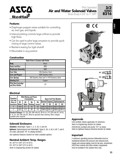
ASCO电磁阀样本ASCO是全球著名的电气自动化控制设备供应商,其电磁阀产品被广泛应用于工业控制领域。
本样本将介绍ASCO电磁阀的基本原理、特点、应用场景以及产品系列。
一、基本原理二、特点1.高可靠性:ASCO电磁阀采用优质材料制造,具有耐高温、耐腐蚀、耐磨损等特性,保证了其在恶劣环境下长期稳定运行。
2.快速响应:ASCO电磁阀的线圈设计精良,能够迅速响应控制信号,并实现阀门的切换动作,满足实时性要求。
3.低能耗:ASCO电磁阀采用优化设计的线圈和结构,能够最大限度地降低能耗,提高能源利用效率。
4.安全可靠:ASCO电磁阀具备过流、过压、过温等保护功能,能够保证系统的安全稳定运行。
三、应用场景1.工业自动化:ASCO电磁阀可用于控制液体或气体的流量、压力和方向,广泛应用于自动化生产线、机械设备、工业机器人等领域。
2.环境保护:ASCO电磁阀可用于空气净化、废气处理、水处理等领域,进行液体或气体的过滤、分离、排放控制,实现环境保护和能源节约。
3.医疗器械:ASCO电磁阀在医疗设备中起到控制液体或气体流通的重要作用,如呼吸机、注射器、输液器等。
四、产品系列1.2/2通径电磁阀系列:适用于液体或气体的流量控制和切断,具有快速响应、可靠性高的特点。
2.3/2通径电磁阀系列:适用于在液体或气体系统中实现液体流向的切换和控制。
3.5/2、5/3通径电磁阀系列:适用于多通道的液体或气体流通系统,实现多位置的流量控制。
4.按钮式电磁阀系列:适用于手动控制液体或气体流通的场景,具有简单易用、可靠性高的特点。
五、结语ASCO电磁阀是一种应用广泛的电气自动化控制设备,其高可靠性、快速响应、低能耗的特点得到了用户的一致好评。
在工业控制、环境保护、医疗器械等领域,ASCO电磁阀发挥了重要的作用。
随着自动化技术的不断发展,ASCO电磁阀将继续以其卓越的性能推动工业自动化的进步。
ASCO黄铜材质电磁阀的工作原理ASCO黄铜材质电磁阀的工作原理ASCO黄铜材质电磁阀为双线圈控制,一个线圈瞬间通电后关闭电源、阀打开,另一个线圈瞬间通电后关闭电源、阀关闭。
可以长时间保持关闭或打开状态,能使线圈寿命更长。
在高温管道中使用佳。
它广泛应用于冶金、石化、制药、烟草、食品医疗、城建环保、给排水、采暖空调、消防安全、科研、节能产业等各个领域。
ASCO电磁阀238系列SCE238D005(220VAC)通用电磁阀原装ASCO型号:SCE238D005(220VAC)品牌:ASCO电压:220VAC尺寸:1寸,DN25压力和温度:0.3-10公斤常温ASCO黄铜材质电磁阀主要技术参数:通径范围:DN1~DN10。
控制方式:常开、常闭。
电源电压: DC12~220V(直流电佳)、 AC24~220V阀体材质:铸钢、黄铜、铝、四氟乙烯、不锈钢。
适用介质:水、气、油、腐蚀流体等。
压力范围:0~2.5MPa温度范围:-50~(+120、+200)。
介质粘度:小于50C St(大于时需定制)。
防护性能:防尘、防水、防爆。
根据工况选择。
接线方式:接线座式;引线式;插头式。
连接方式:法兰、焊接、内螺纹(外螺纹和特殊接口可定做或加转接头)。
阿斯卡ASCO二位三通电磁阀的技术参数:型号规格:DN1~DN500适用压力:0.02~20MPa适用介质:气、水、油、蒸汽、制冷剂、腐蚀性流体介质温度:-200~+200℃介质粘度:小于50CSt(大于时需定制)防护性能:防水、防爆、防腐(铸铁体除外)防爆标志:ExdⅡCT5阀门材质:304、316、铸铁控制方式:一进二出、二进一出, 一进一出电源电压:DC3~127V AC36~380VASCO黄铜材质电磁阀的工作原理ASCO 320 系列,也称为 8320,是为广泛的应用而设计的通用电磁阀。
直动式阀门可用于电压范围、恶劣环境、直接安装、滴液控制和使用时长结构。
它们适用于分析和诊断设备、除尘器系统以及冲压车间和金属冲压.这个系列的黄铜材质规格型号有:8320G130 8320G001 8320G212 8320G083 8320G213 8320G003 8 320G214 8320G172 8320G174 8320G176 8320G178 8320G132 8320G013 8320G215 8320G015 8320G017 8320G182 8 320G184 8320G186 8320G188 8320G136 8320G192。
01527Z H -2020/R 01供货、设计和规格可能改变,恕不另行通知。
保留�有�利。
特性与优点• 多种流量和额定压力范围可选• 阀芯套管可快速拆卸,便于维护内部部件• 密封件有 NBR 、FPM 、EPDM 可选,适用于各种工作温度,多种流体介质• 标准手操机构,安装方便(仅适用于 1/8" ��)• 此电磁阀 AC/DC 可互换,无需拆卸阀门(仅适用于 1/8" ��)• 符合 UL429 和 EN 60335 认证• 符合 NSF 169 和 EC 1935/2004 认证参见“15 位产品代码”• 紧凑型、轻量化阀体设计• 此电磁阀符合所有相关的 EU 和 EAC 认证指令一般信息差压参见 «规格» [1bar = 100kPa]环境温度范围-10°C 至 +60°C (14°F 至 140°F )最大粘度40cSt (mm 2/s)响应时间10 - 20ms (1/8" ��)(✶) 确保与材料接触的流体的相容性得到验证阀体黄铜或不锈钢,AISI 316屏蔽线圈铜阀芯套管不锈钢阀芯和插塞螺母不锈钢弹簧不锈钢�封件FPM 或 EPDM 或 NBR 或 HNBR 阀盘FPM 或 EPDM 或 RUBY 或 NBR 或 CR70N 阀座黄铜或不锈钢 AISI 303电气特性线圈绝缘级别F (H - 认证中)接头扁平插头(电缆 Ø 6-8mm 或 Ø 6-10mm )接头规格DIN 43650,11mm ,行业标准 B (01 型) 或 ISO 4400/EN 175301-803,A 型(02 型)常闭ASCO™ 电磁阀2/2256系列2 通,常闭/常开,直动式,1/8" 或 1/4" 螺纹常开常开功能 (1/8)请访问我们的网站:/asco901527Z H -2020/R 01供货、设计和规格可能改变,恕不另行通知。
g551a001ms说明书型号:G551A001MS加工定制:是材质:铜连接形式:螺纹类型(通道位置):直通式驱动方式:电磁流动方向:单向适用介质:空气压力环境:常压品牌:美国ASCO公称通径:15 mm零部件及配件:阀体用途:切断阀形态:其他工作温度:常温标准:美标美国ASCO电磁阀G551A001MS 系列电磁阀用于气动阀门“开启”或“关闭”的电控操作。
符合NAMUR连接标准,直接安装在气动执行器侧面,无需管子连接。
根据仪表控制系统需要选择单电控或双电控。
二位五通电磁阀配双作用式执行器。
二位三通电磁阀配单作用式执行器。
同时该产品有基本型(IP67)和防爆型,防爆级别为EXD II BT4,其防爆级别适用于工厂的易爆环境场所。
也可根据需要选择合适的电压。
技术参数:结构形式滑动动作方式电磁铁或手动操作,按下并旋转手动操作钮可实现手动状态锁定。
气动弹簧复位,机械弹簧复位,电磁铁操作复位。
复位方式ISO228/1标准G1/4,ISO228/1 standardG1/4接口1/4,3/8,1/2环境温度-20ºC~ 80 ºC(防爆型Explosion-proof-15 ºC~ 50 ºC)介质温度阀体和内部零件:阳较电镀铝合金,铜。
加固端盖:塑料。
材质密封圈:丁苯橡胶(NBR)和聚亚安酯(AU)。
安装符合NAMUR标准和VDI/VDE3845的双孔。
电气数据:标准电压24VDC,24VAC50Hz\\220VAC50Hz特殊电压6V~110VDC,12V~254VAC,50或Or 60Hz电压偏差±10%标准和防爆(Exd II BT4)线圈± 10%功耗标准线圈:AC启动功率6VA,稳定功率4.3VA(热态)DC2.6W(热态),3W(冷态)工作方式高标准ED(DB),连续操作。
防护等级IP65带符合DIN40050的正确安装连接器电气连接PG9连接器。
4167Features•High flow/high-pressure bodies with manual reset toprevent inadvertent valve start-up •Once tripped, can only be manually reset•Electrically Tripped (trips when energized), No Voltage Release (trips when de-energized), or Free Handle constructions•Available for Latched Open or Latched Closed operation •Ideal for controlling critical processes•Some constructions can control aggressive fluids, including steam•Intrinsically Safe constructions are availableSolenoid EnclosuresNominal Ambient T emp. RangesAC: -20˚F to 104˚F (-29˚C to 40˚C)DC: -20˚F to 77˚F (-29˚C to 25˚C)Refer to Engineering Section for details.ApprovalsCSA certified. Some constructions meet shock and vibration ISA S71.03C2.Refer to Engineering Section for details.Standard:RedHat metal solenoid enclosure.Type 1 General Purpose Junction Box.Optional:Explosionproof and Watertight, Types 3, 7 (C and D), and 9.(To order, add prefix "EF" to catalog number.)See Optional Features Section for other available options.Operation AlternativesElectrically Tripped –Valves move to latched position when the solenoid is de-energized, trips when they receive a continuous or momentary (at least 0.3 seconds) electrical signal. When tripped, they can be manually cycled open/closed, but must be reset when the solenoid has once again been de-energized.No Voltage Release –Valves move to latched position when the solenoid is energized, trips when de-energized. When tripped, they can be manually cycled open/closed, but must be reset when the solenoid has once again been energized.Free Handle –Valves move to latched position when the solenoid is energized, trips when de-energized.They cannot be manally cycled open/closed when de-energized. They can be manually cycled open/closed or reset only when energized.Specifications (English units)S P E C I A L S E R V I C E P I L O T169Flow Diagrams170Dimensions:inches (mm)S P E C I A L S E R V I C E P I L O T171Dimensions:inches (mm)Dimensions: inches (mm)172S P E C I A L S E R V I C E P I L O T173Dimensions: inches (mm)3/2SERIES8037/83088310Manual Reset4SPECIAL SERVICE PILOT174Dimensions:inches (mm)。
SJ-1R1Flow (Qv at 6 bar)1100 l/min (ANR)Fl uids ( ) Temperature Range (TS)Sealings ( )air, inert gas, fi ltered- 10°C to + 60°CNBR (nitrile) + PUR (polyurethane)MATERIALS IN CONTACT WITH FLUIDBody Aluminium, black anodized End cover (spring) Glass-fi lled P Alnternal partsZamak, stainless steel, (POM), aluminium Stainless steel Core and plugnutSealingsNBR+PUR Shading coil CopperSPECIFICATIONS● Available feature- Not available( ) RP - Reduced Power, MP - Medium Power•••• Ensure that the compatibility of the fluids in contact with the materials is verifiedPipe Size Orifice Size FlowCoefficientKvOperating PressureDifferential (bar)PowerLevel Prefix Optioonal SolenoidsBasic Catalog NumberMin.Max. (PS)ATEX / IECEX / NEPSIIP65Air Ex m(G)(mm)(m 3/h)(l/min)AC DC AC/DC PV SC NAMUR 3/2 NC - 5/2 - Solenoid air pilot operated - spring return (Single Solenoid)1/460.9515.521010RP -G531C001 MS 1/460.9515.521010MP -G531C001 MS NAMUR 3/2 NC - 5/2 - Solenoid air pilot operated - spring return (Double Solenoid)1/460.9515.521010RP -G531C002 MS 1/460.9515.521010MP -G531C002 MS THREADED 5/2 - Solenoid air pilot operated - spring return (Single Solenoid)1/460.9515.521010RP -G531C017 MS 1/460.9515.521010MP -G531C017 MS THREADED 5/2 - Solenoid air pilot operated (Double Solenoid)1/460.9515.521010RP -G531C018 MS 1/460.9515.521010MP -G531C018 MS••••ORDERING EXAMPLES:SERIES 531EXPLANATION OF TEMPERATURE RANGES OF SOLENOID VALVESValve temperature range The valve temperature range is determined by the selected seal material, the temperature range for proper operation of the valve and sometimes by the fluid ( e.g. steam )Operator ambient temperature rangeThe operator ambient temperature range is determined by the selected power level ( LP, RP, MP or BP ) and the ATEX safety codeTotal temperature rangeThe temperature range of the complete solenoid valvle is determined by the limitations of both temperature range aboveELECTRICAL CHARACTERISTICSCoil insulation class FElectrical safety IEC 335Standard voltages DC 24V - 48VAC 24V - 48V - 115V - 230V/50Hz(Other voltages and 60 Hz available on request)SJ-2R1ADDITIONAL OPTIONSELECTRICAL CONNECTIONSPrefix Connection SC Spade plug connector with cable gland DIN 43650, 11mm, industry standard B, for cables with an outer diameter from 6 to 8 mm (Type 01 / 03) PVMoulded - in cable, standard length 2m (Type 02 / 04)・Other pipe threads are available on request・Plug with visual indication and peak voltage suppression or with cable length of 2m, SC prefix only (Consult ASCO NUMATICS Ofices) ・Moulded-in cable, standard length 2m (Type 02 /04)Prefix OptionCoil TypeNorminal Power RatingOperator AmbientTemperatureRange (TS)(。
SeriesVCEFOPERATORfor potentially explosive atmospheresflameproof/encapsulation Ex d mb II CT3~T6 GbEx mbD 21 tD A21 IP66/67 T85°C~T200°CaluminiumFEATURES• Explosion proof Junction Box Enclosure for the wiring of ASCO solenoids • Intended for use in potentially explosive atmospheres, according to Directive Chinese Standard - GB• NEPSI certificate (GYJ11.1695X) in compliance with GB3836.1, GB3836.2, GB3836.9, G B12476.1• Electrostatic epoxy powder paint, stainless steel screws, and molded epoxy coils provide excellent protection in corrosive environment• Factory pre-wired and assembled to any explosion proof ASCO RedHat II solenoid valve• Easy electrical installation and installation cost reduction by means of a separate explosion proof splice box to terminate solenoid valves’ wiring• Enclosure comes with 12 combination choices of 4 different conduit directions and 3 sizes of conduit entriesCONSTRUCTIONHousing & Cover Gasket CoilGround Screws Terminal Block ELECTRICAL CHARACTERISTICSStandard VoltagesSAFETY CODEEpoxy painted die ca st aluminium Silicon (VMQ)Epoxy molded Stainless Steel CeramicAC: 24, 120, 240, 480 volts, 60 Hz or (110, 220 volts, 50 Hz)DC: 6, 12, 24, 120, 240 volts(Valves with VCEF housing maintain wattage and current ratings as shown on individual catalog sheets.)Ex d mb II CT3~T6 Gb,Ex mbD 21 tD A21 IP66/67 T85°C~T200°CPOWER LEVELSelectrical holding values (watt)P C -V C E F -2016/R 1.1(1)Make sure that the selected ambient temperature does not exceed the allowable valve temperature characteristics as specified on the appropriate valve catalog sheets (2)AC (~) rectified coil constructionTEMPERATURE CLASSIFICATIONThe minimum allowable ambient temperature is -40°C for the operator. Select the requested “T” classification from the temperature classification tables (AC or DC), respecting the maximum ambient temperature and cold (20°C) electrical holding power values.AC (~) SolenoidsDC (=) SolenoidsPower Level (watt)Solenoid SizeI n s u l a t i o n C l a s s"T"Classi fi cation Maximum Ambient (1)Temp.(°C)M 6M X XM 12Reduced Power (RP)3.5•F T4/T135°C 60Basic Power (BP)6.1•F T4/T135°C526.1•H T4/T135°C 608.1•F T4/T135°C 528.1•H T4/T135°C 609.1•F T3/T200°C 529.1•F T4/T135°C 409.1•H T3/T200°C 609.1•H T4/T135°C 4010.1•F T4/T135°C 5210.1•H T4/T135°C 6011.1•F T3/T200°C 5211.1•F T4/T135°C 4011.1•H T3/T200°C 6011.1•HT4/T135°C 4012.0(2)•F T4/T135°C 5515.1•F T3/T200°C 4015.1•F T4/T135°C 5516.1•F T4/T135°C 5216.1•H T4/T135°C 5517.1•F T3/T200°C 4017.1•H T3/T200°C 4020.1•F T3/T200°C 2220.1•H T3/T200°C22Power Level(watt)SolenoidSize I n s u l a t i o n C l a s s"T"Classi fi cation MaximumAmbient (1)Temp.(°C)M 6M X X Low Power (LP)0.55•FT6/T85°C 650.70•H T5/T100°C 800.70•F T6/T85°C 650.75•F T6/T85°C 651.40•F T6/T85°C 601.70•F T6/T85°C 601.80•F T5/T100°C 741.80•F T6/T85°C 552.00•F T5/T100°C 742.00•F T6/T85°C 55Basic Power (BP)10.60•F T4/T135°C 5510.60•H T4/T135°C 5511.60•F T4/T135°C 5511.60•H T4/T135°C 5512.60•F T4/T135°C 3518.60•F T4/T135°C 3018.60•H T4/T135°C 3020.60•H T4/T135°C 3022.60•F T4/T135°C 3522.60•H T4/T135°C 3524.60•HT4/T135°C35(3)Prefix VCEF - It comes with 12 combination choices of 4 different conduit directions and 3 conduit entries sizes. Refer to details under ORDERING EXAMPLES VALVESSERIES VCEFPREFIX TABLEVCEF prefix *options A = option A B = option B C = option C D = option D conduit sizes M = 1/2" NPT N = 3/4" NPT P = M20*1.5basic numbersuffixvoltageG551H401110V / 50HzMO M C INSTALLATIONORDERING EXAMPLES VALVES:Add prefix corresponding to specific conduit size required to any RedHat II valve catalog number & specify the voltage.*options• Installation/Maintenance instructions are included with each valve• The solenoid operators can be mounted in any position without affecting operation• For optimum life and performance, the solenoid should be mounted vertically and upright to reduce the possibility of foreign matter accumulating in the solenoid base sub-assembly area • Internal and external earthing connectionPrefixDescription1234567V C E F Flameproof/Encapsulated - Aluminium NEPSI (GB3836)(3)H T Class H - High temperatureX Other special constructionsOPTION: AOPTION: BOPTION: COPTION: DDIMENSIONS(mm), WEIGHT(kg)P C -V C E F -2016/R 1.1va i l ab i l i t y , d e s i g n a n d s p ec i fi c a t i o n s a r e s u b j e c t t o c h a n g e w i t h o u t n o t i c e . A l l r i g h t s r e s e r v ed .SOLENOID SIZEA(mm)*WEIGHT M61290.75kg MXX 1360.75kg M121360.75kg* weight excludes solenoid。