GSR电磁阀说明书
- 格式:pdf
- 大小:164.11 KB
- 文档页数:4
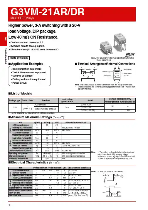
G3VM-21AR/DR Higher power, 3-A switching with a 20-Vload voltage, DIP package.Low 40 mΩ ON Resistance.•Continuous load current of 3 A.•Switches minute analog signals.•Dielectric strength of 2,500 Vrms between I/O.■Application Examples■Terminal Arrangement/Internal Connections■List of Models*The AC peak and DC value are given for the load voltage.■Absolute Maximum Ratings (Ta = 25°C)RoHS compliant Note: The actual product is marked differently from theimage shown here.•Communication equipment•Test & Measurement equipment•Security equipment•Factory Automation equipment•Power circuitOMRON logoPin 1 markModel nameMold pin mark ∗LOT No.Note: The actual product is marked differently from the image shown here.∗The indentation in the corner diagonally opposite from the pin 1 mark is froma pin on the mold.Package type Contact form TerminalsLoad voltage(peak value) *ModelMinimum package quantityNumber per stick Number per tape and reel DIP41a(SPST-NO)PCB terminals20 VG3VM-21AR100---Surface-mounting terminalsG3VM-21DRG3VM-21DR (TR)---1,500 Item Symbol Rating Unit Measurement conditionsInputLED forward current I F30mANote: 1. The dielectric strength between the input andoutput was checked by applying voltagebetween all pins as a group on the LED side andall pins as a group on the light-receiving side.Repetitive peak LED forward current I FP 1 A100µs pulses, 100 ppsLED forward current reduction rate∆I F/°C−0.3mA/°C Ta ≥ 25°CLED reverse voltage V R 5 VConnection temperature T J125 °COutputLoad voltage (AC peak/DC)V OFF20VContinuous load current (AC peak/DC)I O3AON current reduction rate∆I O/°C−30 mA/°C Ta ≥ 25°CPulse ON current Iop9A t = 100 ms, Duty = 1/10Connection temperature T J125 °CDielectric strength between I/O (See note 1.)V I-O2500Vrms AC for 1 minOperating temperature Ta −40 to +85°C With no icing or condensationStorage temperature Tstg−55 to +125°C With no icing or condensationSoldering temperature---260 °C10 s12G3VM-21AR/DRMOS FET RelaysG3VM-21AR/DR■Recommended Operating ConditionsUse the G3VM under the following conditions so that the Relay will operate properly.■Engineering Data■Safety Precautions•Refer to "Common Precautions" for all G3VM models.ItemSymbol MinimumTypical MaximumUnit Load voltage (AC peak/DC)V DD ------16V Operating LED forward current I F 51025mA Continuous load current (AC peak/DC)I O ------3AOperating temperatureTa−20 ---65 °CLED forward current vs.Ambient temperatureContinuous load current vs.Ambient temperatureLED forward current vs.LED forward voltageContinuous load current vs.On-state voltageOn-state resistance vs.Ambient temperatureTrigger LED forward current vs.Ambient temperatureTurn ON, Turn OFF time vs.LED forward currentTurn ON, Turn OFF time vs.Ambient temperatureCurrent leakage vs.Ambient temperatureI F - TaAmbient temperature Ta (°C)L E D f o r w a r d c u r r e n t I F (m A )03010204050-40100806040200-20I O - TaAmbient temperature Ta (°C)C o n t i n u o u s l o a d c u r r e n t I O (A )-40100806040200-2004321I - V LED forward voltage V F (V)0.01L E D f o r w a r d c u r r e n t I F(m A )I O - V ONOn-state voltage V ON (V)-4-3-2-1C o n t i n u o u s l o a dc u r r e n t I O (A )R - Ta60204080100Ambient temperature Ta (°C)O n -s t a t e r e s i s t a n c e R O N (m Ω)I FT - TaAmbient temperature Ta (°C)012T r i g g e r L E D f o r w a r d c u r r e n t I F T (m A )t , t - ILED forward current I F (mA)0.010.110100T u r n O N , T u r n O F F t i m e t O N , t O F F (m s )t, t - TaAmbient temperature Ta (°C)T u r n O N , T u r n O F F t i m e t O N , t O F F (m s )I LEAK - TaAmbient temperature Ta (°C)0.011001010.1C u r r e n t l e a k a g e I L E A K (n A )■Dimensions(Unit: mm) Note: The actual product is marked differently from theimage shown here.PCB Dimensions (Bottom View)Actual Mounting Pad Dimensions(Recommended Value, Top View)Note: The actual product is marked differently from the image shown here.∗ The indentation in the corner diagonally opposite from the pin 1 mark is from a pin on the mold.+0.1−0.05PCB TerminalsWeight: 0.25 gSurface-mounting TerminalsWeight: 0.25 g• Application examples provided in this document are for reference only. In actual applications, confirm equipment functions and safety before using the product.• Consult your OMRON representative before using the product under conditions which are not described in the manual or applying the product to nuclear control systems, railroad systems, aviation systems, vehicles, combustion systems, medical equipment, amusement machines, safety equipment, and other systems or equipment that may have a serious influence on lives and property if used improperly. Make sure that the ratings and performance characteristics of the product provide a margin of safety for the system or equipment, and be sure to provide the system or equipment with double safety mechanisms.Cat. No. K135-E1-020412(0412)(O)Note: Do not use this document to operate the Unit. OMRON CorporationELECTRONIC AND MECHANICAL COMPONENTS COMPANY Contact: /ecb。
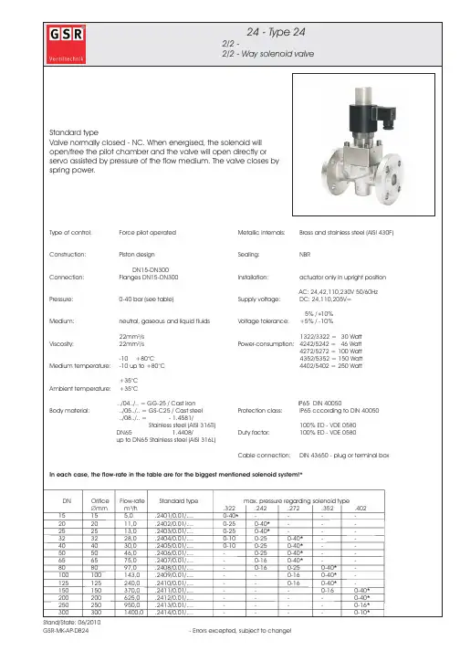
电磁阀的使用说明选型要领:电磁阀选型首先应该依次遵循安全性,可靠性,适用性,经济性四大原则,其次是根据六个方面的现场工况(即管道参数、流体参数、压力参数、电气参数、动作方式、特殊要求进行选择)。
选型依据:一、根据管道参数选择电磁阀的:通径规格(即DN)、接口方式1、按照现场管道内径尺寸或流量要求来确定通径(DN)尺寸。
2、接口方式,一般>DN50要选择法兰接口,≤DN50则可根据用户需要自由选择。
二、根据流体参数选择电磁阀的:材质、温度组1、腐蚀性流体:宜选用耐腐蚀电磁阀和全不锈钢;食用超净流体:宜选用食品级不锈钢材质电磁阀。
2、高温流体:要选择采用耐高温的电工材料和密封材料制造的电磁阀,而且要选择活塞式结构类型的。
3、流体状态:大至有气态,液态或混合状态,特别是口径大于DN25订货时一定要区分开来。
4、流体粘度:通常在50cSt以下可任意选择,若超过此值,则要选用高粘度电磁阀。
三、根据压力参数选择电磁阀的:原理和结构品种1、公称压力:这个参数与其它通用阀门的含义是一样的,是根据管道公称压力来定。
2、工作压力:如果工作压力低则必须选用直动或分步直动式原理;最低工作压差在0.04Mpa以上时直动式、分步直动式、先导式均可选用。
四、电气选择:电压规格应尽量优先选用AC220V、DC24较为方便。
五、根据持续工作时间长短来选择:常闭、常开、或可持续通电1、当电磁阀需要长时间开启,并且持续的时间多余关闭的时间应选用常开型。
2、要是开启的时间短或开和关的时间不多时,则选常闭型。
3、但是有些用于安全保护的工况,如炉、窑火焰监测,则不能选常开的,应选可长期通电型。
六、根据环境要求选择辅助功能:防爆、止回、手动、防水雾、水淋、潜水1、爆炸性环境:必须选用相应防爆等级的电磁阀2、当管内流体有倒流现象时,可选择带止回功能电磁阀。
3、当需要对电磁阀进行现场人工操作时,可选择带手动功能电磁阀。
4、露天安装或粉尘多场合应选用防水,防尘品种(防护等级在IP54以上)。
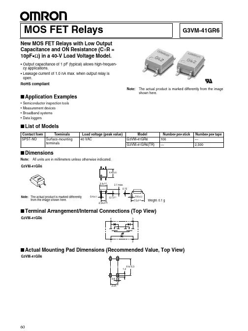
G3VM-41GR6MOS FET RelaysNew MOS FET Relays with Low Output Capacitance and ON Resistance (C ×R = 10pF •Ω) in a 40-V Load Voltage Model.•Output capacitance of 1 pF (typical) allows high-frequen-cy applications.•Leakage current of 1.0 nA max. when output relay is open.RoHS compliant!■Application Examples•Semiconductor inspection tools •Measurement devices •Broadband systems •Data loggersNote:The actual product is marked differently from the image shown here.■List of Models■DimensionsNote:All units are in millimeters unless otherwise indicated.■Terminal Arrangement/Internal Connections (Top View)■Contact form Terminals Load voltage (peak value)ModelNumber per stick Number per tape SPST-NOSurface-mounting terminals40 VACG3VM-41GR6100---G3VM-41GR6(TR)---2,500G3VM-41GR6Note:The actual product is marked differentlyfrom the image shown here.Weight: 0.1 gG3VM-41GR6G3VM-41GR6G3VM-41GR6G3VM-41GR6■Absolute Maximum Ratings (Ta = 25°C)■Electrical Characteristics (Ta = 25°C)■Recommended Operating ConditionsUse the G3VM under the following conditions so that the Relay will operate properly.■Engineering DataLoad Current vs. Ambient TemperatureG3VM-41GR6■Safety PrecautionsRefer to “Common Precautions” for all G3VM models.ItemSymbol Rating Unit Measurement ConditionsInputLED forward currentI F 50mARepetitive peak LED forward currentI FP1A 100 µs pulses, 100 pps LED forward current reduction rate∆ I F /°C −0.5mA/°C Ta ≥ 25°CLED reverse voltage V R 5V Connection temperatureT j 125°C OutputOutput dielectric strength V OFF 40V Continuous load current I O 120mA ON current reduction rate ∆ I ON /°C −1.2mA/°C Ta ≥ 25°CConnection temperatureT j 125°C Dielectric strength between input and output (See note 1.)V I-O 1,500Vrms AC for 1 minOperating temperature T a −20 to +85°C With no icing or condensation Storage temperature T stg −55 to +125°C With no icing or condensation Soldering temperature (10 s)---260°C10sNote:1.The dielectric strength between the input andoutput was checked by applying voltage be-tween all pins as a group on the LED side and all pins as a group on the light-receiving side.ItemSymbol Mini-mum Typical Maxi-mum UnitMeasurement conditions InputLED forward voltage V F 1.0 1.15 1.3V I F = 10 mA Reverse currentI R ------10µA V R = 5 V Capacity between terminals C T ---15---pF V = 0, f = 1 MHz Trigger LED forward currentI FT ------4mA I O = 100 mA OutputMaximum resistance with output ON R ON ---1015ΩI F = 5 mA,I O = 120 mA, t < 1 s Current leakage when the relay is openI LEAK ------ 1.0nA V OFF = 30 V, Ta = 50°C Capacity between terminalsC OFF --- 1.0 2.0pF V = 0, f = 100 MHz, t < 1 sCapacity between I/O terminals C I-O ---0.8---pF f = 1 MHz, Vs = 0 V Insulation resistance R I-O 1,000------M ΩV I-O = 500 VDC, RoH ≤ 60%Turn-ON time tON ------0.5ms I F = 10 mA, R L = 200 Ω, V DD = 20 V (See note 2.)Turn-OFF timetOFF------0.5ms Note:2.Turn-ON and Turn-OFFTimesItemSymbol MinimumTypicalMaximumUnitOutput dielectric strength V DD------32V Operating LED forward current I F 10---30mA Continuous load current I O ------120mA Operating temperatureT a25---60°CCommon Precautions!WARNINGBe sure to turn OFF the power when wiring the Relay, other-wise an electric shock may be received.!WARNINGDo not touch the charged terminals of the SSR, otherwise an electric shock may be received.!CautionDo not apply overvoltage or overcurrent to the I/O circuits of the SSR, otherwise the SSR may malfunction or burn.!CautionBe sure to wire and solder the Relay under the proper soldering conditions, otherwise the Relay in operation may generate ex-cessive heat and the Relay may burn.Typical Relay Driving Circuit ExamplesUse the following formula to obtain the LED current limiting resis-tance value to assure that the relay operates accurately.Use the following formula to obtain the LED forward voltage value to assure that the relay releases accurately.Protection from Surge Voltage on the Input TerminalsIf any reversed surge voltage is imposed on the input terminals, insert a diode in parallel to the input terminals as shown in the fol-lowing circuit diagram and do not impose a reversed voltage value of 3V or more.Surge Voltage Protection Circuit ExampleProtection from Spike Voltage on the Output TerminalsIf a spike voltage exceeding the absolute maximum rated value isgenerated between the output terminals, insert a C-R snubber or clamping diode in parallel to the load as shown in the following circuit diagram to limit the spike voltage.Spike Voltage Protection Circuit ExampleUnused Terminals (6-pin models only)Terminal 3 is connected to the internal circuit. Do not connect anything to terminal 3 externally.Pin Strength for Automatic Mountingn order to maintain the characteristics of the relay, the force imposed on any pin of the relay for automatic mounting must not exceed the following.In direction A: 1.96 NIn direction B: 1.96 NLoadTransistor10 to 100 kΩLoadR1 =V CC− V OL− V F (ON) 5 to 20 mAV F (OFF) = V CC− V OH < 0.8 VLoad ConnectionDo not short-circuit the input and output terminals while the relay is operating or the relay may malfunction.Solder MountingPerform solder mounting under the following recommended con-ditions to prevent the temperature of the Relays from rising.<Flow Soldering>Through-hole Mounting (Once Only)Note:We recommend that the suitability of solder mounting be verified under actual conditions.<Reflow Soldering>Surface Mounting DIP or SOP Packages (Twice Max.) Surface Mounting SSOP Packages (Twice Max.)Note: 1.We recommend that the suitability of solder mounting be verified under actual conditions.2.Tape cut SSOPs are packaged without humidity resis-tance. Use manual soldering to mount them.Manual Soldering (Once Only)Manually solder at 350°C for 3 s or less or at 260°C for 10 s or less.SSOP Handling Precautions<Humidity-resistant Packaging>Component packages can crack if surface-mounted components that have absorbed moisture are subjected to thermal stress when mounting. To prevent this, observe the following precau-tions.1.Unopened components can be stored in the packaging at 5to 30°C and a humidity of 90% max., but they should be used within 12 months.2.After the packaging has been opened, components can bestored at 5 to 30°C and a humidity of 60% max., but they should be mounted within 168 hours.3.If, after opening the packaging, the humidity indicator turnspink to the 30% mark or the expiration data is exceeded, bake the components while they are still on the taping reel, and use them within 72 hours. Do not bake the same com-ponents more than once.Baking conditions: 60±5°C, 64 to 72 hExpiration date: 12 months from the seal date(given on the label)4. f the same components are baked repeatedly, the tapedetachment strength will change, causing problems when mounting. When mounting using dehumidifying measures, always take countermeasures against component damage from static electricity.5.Do not throw or drop components. If the laminated packag-ing material is damaged, airtightness will be lost.6.Tape cut SSOPs are packaged without humidity resistance.Use manual soldering to mount them.AC ConnectionDC Single Connection DC Parallel Connection LoadLoadLoadLoadSolder type Preheating SolderingLead solderSnPb150°C60 to 120 s230 to 260°C10 s max.Lead-free solderSnAgCu150°C60 to 120 s245 to 260°C10 s max.Solder type Preheating SolderingLead solderSnPb140→160°C60 to 120 s210°C30 s max.Peak240°C max.Lead-free solderSnAgCu180→190°C60 to 120 s230°C30 to 50 sPeak260°C max.Solder type Preheating SolderingLead solderSnPb140→160°C60 to 120 s210°C30 s max.Peak240°C max.Lead-free solderSnAgCu150→180°C120 s max.230°C30 s max.Peak250°C max.。
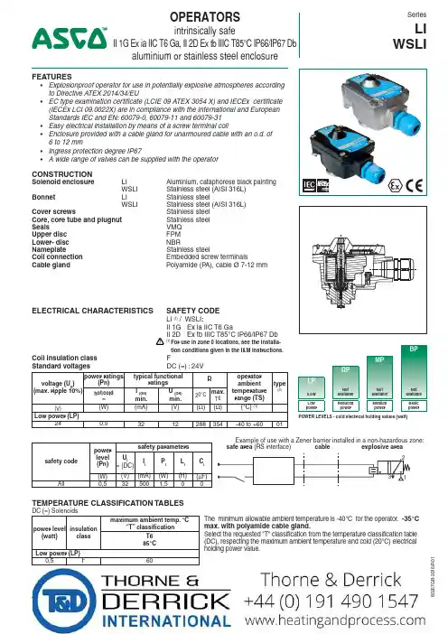
OPERATORSintrinsically safeII 1G Ex ia IIC T6 Ga, II 2D Ex tb IIIC T85°C IP66/IP67 Dbaluminium or stainless steel enclosureSeriesLI WSLI16/R 01FEATURES• Explosionproof operator for use in potentially explosive atmospheres according to Directive A TEX 2014/34/EU• EC type examination certificate (LCIE 09 ATEX 3054 X) and IECEx certificate (IECEx LCI 09.0022X) are in compliance with the International and European Standards IEC and EN: 60079-0, 60079-11 and 60079-31• Easy electrical installation by means of a screw terminal coil• Enclosure provided with a cable gland for unarmoured cable with an o.d. of 6 to 12 mm• Ingress protection degree IP67• A wide range of valves can be supplied with the operatorCONSTRUCTIONSolenoid enclosure LI Aluminium, cataphorese black painting WSLI Stainless steel (AISI 316L)Bonnet LI Stainless steel WSLI Stainless steel (AISI 316L)Cover screws Stainless steel Core, core tube and plugnut Stainless steel Seals VMQ Upper disc FPM Lower- disc N BR ameplate Stainless steel Coil connection Embedded screw terminals Cable gland Polyamide (P A), cable Ø 7-12 mmELECTRICAL CHARACTERISTICS SAFETY CODELI (1) / WSLI :II 1G Ex ia IIC T6 GaII 2D Ex tb IIIC T85°C IP66/IP67 Db!(1) For use in zone 0 locations, see the installa-tion conditions given in the I&M instructions.Coil insulation class FStandard voltagesDC (=) : 24Vvoltage (U n )(max. ripple 10%)power ratings(Pn)typical functionalratings R operator ambient temperature range (TS)type(3)hot/cold =I (ON)min.U (ON)min.20°C max.T6(V)(W)(mA)(V)(Ω)(Ω)(°C) (1)Low power (LP)240,53212288354-40 to +6001safety codepower level (Pn)safety parameters U i = (DC)I I P I L I C I (W)(V)(mA)(W)(H)(µF)All0,5325001,5TEMPERATURE CLASSIFICATION TABLESDC (=) Solenoids power level (watt)insulationclass maximum ambient temp. °C“T” classificationThe minimum allowable ambient temperature is -40°C for the operator. -35°C max. with polyamide cable gland.Select the requested "T" classification from the temperature classification table (DC), respecting the maximum ambient temperature and cold (20°C) electrical holding power value.T685°C Low power (LP)0,5F60BPMPRPLP0,5W Not available Not available Not available Low powerReduced powerMedium powerBasic powerPOWER LEVELS - cold electrical holding values (watt)ORDERING EXAMPLES VALVES:LI G 551B305MO 24VWSLI 8551A31324Vprefix pipe thread voltage basic numbersuffix16/R 01PRODUCT SELECTION GUIDE(The selection can only be made in conjunction with the appropriate valve catalogue sheet)STEP 1Select basic valve catalogue number, including pipe thread indentificationletter from one of the specification tables on the separate catalogue pages.Example: G551B305STEP 2Select voltage. Refer to standard voltages on page 1.Example: 24V / DC STEP 3Select solenoid prefix (combination). Refer to the prefix table on this page and respect the indicated power level, cold electrical holding values and "T" classification mentioned on page 1.NOTE: Make sure that the ambient temperature does not exceed the allowable valve temperature characteristics.Example: LI 60°C ambient L ow Power (LP) 0,5 W II 1G Ex ia IIC T6 Ga II 2D Ex tb IIIC T85°C IP67 Db STEP 4Final catalogue / ordering number. Example:LI G551B305 24V / DCPREFIX TABLEprefixdescriptionpower level 1234567LP RP MP BPL I I.S. with aluminium IP67 enclosure (EN/IEC 60079-11, -31)❍---W S LII.S. with 316L SS IP67 enclosure (EN/IEC 60079-11, -31)❍---XOther special constructions----❍ Available feature in DC only - Not availableADDITIONAL OPTIONS• C able glands (Nickel-plated brass): unarmoured cable, catalogue number 88200011 / armoured cable, catalogue number 88200014INSTALLATION• Multi language installation/maintenance instructions are included with each valve • The solenoid valves can be mounted in any position without affecting operation • Internal and external earthing connection• Electrical connection between solenoid valve and barrier/interface with cable type A or B according to EN 50039• The solenoid can be rotated 360° to select the most favourable position for cable entry16/R 01RECOMMENDED INTERFACESLocated in safe areas, these interfaces allow to feed the intrinsically safe solenoid valves located in explosive areas.This equipment must be ordered from its respective manufacturers, specifying that they are intended to feed intrinsically safe solenoid operators:LI / WSLI: II 1G Ex ia IIC T6 Ga, II 2D Ex tb IIIC T85°C IP66/IP67 DbINTERFACESmanufacturermodule type1G/2G T6IIC ABB DO910Sx Bartec 07-7331-2105/1000x 07-7331-2301/1100x GEORGIN BXNE701002x BXNE70100Ex G.M. InternationalD1040Q-2D1049S x D1042Q-2D5048S x D1043Q-2D5049S x D1048S -x MTLMTL 722+MTL 779x MTL 728+MTL 4524S x MTL 728P+-x Pepperl +FuchsKFD2-SL2-Ex1x KFD2-SL2-Ex1.B x KFD2-SL2-Ex1.LK x KFD2-SL2-Ex2x KFD2-SL2-Ex2.B x KCD0-SD-Ex1.1245x KFD0-SD2-Ex2.1245x LB-2103FB-2203x LB-2105FB-2205x LB-2112FB-2212x PHOENIX CONTACTMACX MCR-EX-SD-24-48-LP(-SP)x MACX MCR-EX-SD-21-60-LP(-SP)x PI-EX-SD-24-48x PI-EX-SD-21-60x Stahl9475/12-04-119175/20-14-11x 9475/12-04-219176/10-14-00x 9475/12-04-319176/20-14-00x 9475/32-04-129175/10-16-11x 9475/32-04-229175/20-16-11x 9475/32-04-729176/10-16-00x 9175/10-14-119176/20-16-00x 9001/01-280-100-101x 9002/13-280-110-001xINTERFACESmanufacturermodule type1G/2G T6IIC TurckMK72-S09-Ex0/24VDC x MC72-41Ex-T/24VDCx MC72-44Ex-Tx Siemens6ES7132-7RD11-0AB0 2 ways x 6ES7132-7RD21-0AB0x 6ES7132-7GD10-0AB0 2 ways x 6ES7132-7GD20-0AB0xZENER BARRIERSBartec07-7331-2301/1001x CEAGSB-3722x SB-2420x SB-3729x SB-3728x SB-0728x GEORGIN BZG728+x BZG2728+x BZG728P+x BZG2728P+x MTL MTL 722MTL 728Px MTL 728MTL 779x Pepperl +Fuchs Z728x Z728.Hx Z728.CLx Stahl 9001/01-199-150-101x 9001/01-280-085-101x 9001/01-280-100-101x 9001/01-280-110-101x In accordance with the zone classification and the national le-gislation of each country, apply the certification procedures for the connection of IS-rated products with associated equipment. All information subject to change without notice. All responsibility for the use of products from other suppliers and the possible modi-fications of their characteristics is disclaimed.-G B -- A v a i l a b i l i t y , d e s i g n a n d s p e c i fic a t i o n s a r e s u b j e c t t o c h a n g e w i t h o u t n o t i c e . A l l r i g h t s r e s e r v e d .16/R 01type prefix power level weight M6LI low power 0,56M6WSLI low power 1,17TYPE LI:Low powerPrefix "LI" SolenoidAluminium, cataphorese black painting IEC and EN: 60079-11, 60079-31II 1G Ex ia IIC T6 Ga, II 2D Ex tb IIIC T85°C IP66/IP67 DbTYPE WSLI:Low powerPrefix "WSLI" Solenoid Stainless steelIEC and EN: 60079-11, 60079-31II 1G Ex ia IIC T6 Ga, II 2D Ex tb IIIC T85°C IP66/IP67 DbDIMENSIONS (mm), WEIGHT (kg)SERIES LI/WSLI。
Stand/State:06/2010-AP-DB- Errors excepted, subject to change!GSR-MK 24 保留技术修改权利 Stand/State:04/2008GSR-MK-JK-DB-24TH 保留技术修改权利 - Errors excepted, subject to change!Stand/State:04/2008GSR-MK-JK-DB-27 保留技术修改权利 - Errors excepted, subject to change!--GSR-MK JK DB35 保留技术修改权利 - Errors excepted, subject to change!Stand/State:05/2010GSR-MK-JK-DB-43 保留技术修改权利 -Errors excepted, subject to change!Stand/State: 06/2008GSR-MK-JM-DB-43TM 保留技术修改权利 - Errors excepted, subject to change!零件单 - Parts listK1.1 阀体 / Valve body K2.1 上阀盖 / Bonnet *K3.1 先导座 / Pilot seat *K3.2 隔膜/ Diaphragm *K3.3 导向管 / Guiding insert *K3.4 先导轴 / Pilot spindle K3.6 螺钉 / Cylinder screw *K3.7 由令螺母 / Union nut *K3.8 O 形圈 / O-ring K3.10 丝堵 / Sealing plug K3.12 垫片 / Disk K3.13 阻尼螺钉/ Damping screw K3.15 过滤器 / Filter retainer *K3.19 O 形圈 / O-ring *K3.23 O 形圈 / O-ring *K3.24 O 形圈 / O-ring K3.25 滤网 / Strainer *K3.26 O 形圈 / O-ring *K3.27 六角螺栓 / Hexagon nut K3.28 六角螺栓 / Hexagon nut *K3.29 六角螺栓 / Hexagon nut *K3.30 O 形圈 / O-ring *K3.31 O 形圈 / O-ring *K3.33 弹簧 / Spring K5.1 电磁管/ Solenoid tube *K5.2 铁芯/ Solenoid plunger *K5.3 铁芯弹簧 / Plunger spring K5.4 压件 / Pressure piece K5.5 O 形圈 / O-ring K5.6 垫片 / Disk K5.7 螺钉 / Cylinder screw K5.8 六角螺栓 / Hexagon nut K5.9 滚纹压片 / Corrugated disk K6.1 电磁/ Solenoid K7.1 接线端子 / Plug型号 / Type D4321-D4323型号 / Type D4324 / D4325型号 / Type B4326 - B4328*= 备件包中的零件*=Part of the spare parts set.7.15.85.96.15.25.15.33.263.12.13.23.303.271.17.15.85.96.15.25.15.33.262.13.293.23.13.301.13.103.153.83.257.15.75.95.45.53.335.66.15.25.55.13.193.273.123.42.13.73.23.11.1调整阀门关闭时间 - SR (G5/4-G2标配)Device for adjustable close damping -SR (From G5/4-G2 standard)螺钉右旋: 阀门关闭速度变慢Screw to the right site :Valve closes slower 螺钉左旋: 阀门关闭速度变快Screw to the left site :Valve closes faster3.283.133.233.103.153.243.25视图 AA--GSR-MK JK DB49 保留技术修改权利 - Errors excepted, subject to change!Stand/State:04/2008GSR-MK-JK-49TH 保留技术修改权利 - Errors excepted, subject to change!Stand/State:05/2010-JK-DB-1/041- Errors excepted, subject to change!GSR-MK 保留技术修改权利 Stand/State:05/2010-JK--- Errors excepted, subject to change!GSR-MK DB 2/164 保留技术修改权利 。
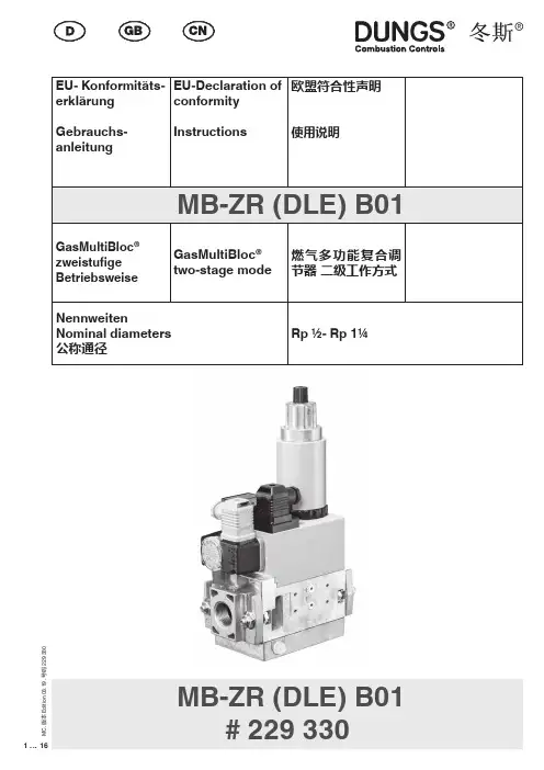
MB-ZR (DLE) B01# 229 3302 (16)M C . 版本 E d i t i o n 03.19 .号码 229 33Dr.-Ing. Karl-Günther Dalsaß,Geschäftsführer / Chief Operating Officer 总经理Urbach, 2018-04-213 (16)M C . 版本 E d i t i o n 03.19 .号码 229 3304 (16)M C . 版本 E d i t i o n 03.19 .号码 229 330GasMultiBloc ® zweistu-fi ge Betriebsweise T yp MB-ZR (DLE) B01NennweitenRp 1/2 - Rp 1 1/4GasMultiBloc ® two-stage operation T yp MB-ZR (DLE) B01Nominal diametres Rp 1/2 - Rp 1 1/4操作和安装说明燃气多功能复合调节器 二级工作方式MB - ZR (DLE) B01 型公称内径Rp 1/2 - Rp 1 1/4Max. BetriebsdruckMax. operating pressure 最大 工作压力p max.V1+V2 Klasse A, Gruppe 2V1+V2 Class A, Group 2V1+V2 A级2类nach / acc. / 根据EN 161SchutzartDegree of protection 保护程度IP 54 nach / acc. / 根据IEC 529 ( DIN 40 050)Familie 1 + 2 + 3Family 1 + 2 + 3系列 1 + 2 + 3Ausgangsdruckbereich Outlet pressure range 输出压力范围S 20 / S 22: 4 - 20 mbar (0,4 - 2 kPa)S 50 / S 52: 4 - 50 mbar (0,4 - 5 kPa)Druckwächter/ Pressure Switch/压力监控器T yp/T ype/型号GW…A5, GW…A2, NB…A2, ÜB…A2nach / acc. / 根据EN 1854FeinsiebFine-mesh sieve A级2类nach / acc. / 根据U n ~(AC) 220 V-15 % …- 230 V+10 %Einschaltdauer/Switch-on duration/ 开关时间 100 %fl e!在液化气设备中使用时,mb-ZR不得在低于0°C下运行。
电磁阀选型应遵从的四项原则德国GSR直动式电磁阀现货特价GSR气动调整阀由执行机构和阀体两部分构成。
不同的生产工艺过程对气动调竹阀有不同的功能需求,因此,为实现这些不同的功能,需要在气动调整阀执行机构配置各种附属装置,来充足生产工艺的需求。
如:为实现失去掌控电源后阀门快关或快开,在执行机构气源管线上安装了GSR电磁阀;为使执行机构翰出较大的力矩,在执行机构气源廿线上安装有压力放大器RELAY;为使阀门快速响应、跟踪掌控信号,安装有流量放大器BOOSTER等。
调竹阀是通过调整流过阀门流体的流量,来实现对工艺系统压力、沮度、流量、液位等工艺参数的掌控。
气动调整阀具有结构简单,调整响应快,性能牢靠等优点,因此在电站中得到了广泛应用。
不同生产厂家生产的气动调整阀,其工作原理各有不同,再加各工艺系统对气动阀不同的功能需求,气动阀的种类、工作原理、调试方法、调试项日及方法千变万化、各不相同,因此,有GSR气动调整阀调试过程中,需针对这些不同和差异,对GSR气动阀的调试方法及项日进行相应地删减。
只有了解系统功能需求,把握了气动调整阀的工作原理,才略作到以不变应万变,对调试方法及项目做到心中有数,调试后的气动调怜阀才略实现“手巧”的日的,搭配调整器的“心灵”完成对工艺系统各参数的精、准、快调150 GSR气动调整阀以压缩空气为能源,具有结构简单、动作牢靠、平衡箱出推力大、价格便宜、维护和修理便利等独特的优点,大大优于液动和电动执行器,因此,在核电站中得到了广泛的应用。
GSR德国气动调整阀常用术语介绍:调整器:又叫掌控器,通过使用某些既定的运算来调怜掌控变量的自动操作装置,在闭环调整系统中又叫PID调怜器。
调竹器的翰入接受关于过程变量状态的信息,然后供给一个相庆的愉出信号弹给终端掌控元件。
死区:箱入信号更改方向但不致于引起箱出信号的可以察看到的变更时,箱入信号的可变更范围。
通常有零点、量程和50%的死区。
线性度:与两个变量有关的一条曲线与一条直线的接近程度。
德国GSR防爆电磁阀安装注意事项及控制方式德国GSR防爆电磁阀是把设备可能点燃爆炸性气体混合物的部件全部封闭在一个外壳内 ,其外壳能够承受通过外壳任何接台面或结构间隙,渗透到外壳内部的可燃性混合物在内部爆炸而不损坏,并且不会弓|起外部由一种、多种气体或蒸e气形成的爆炸性环境的点燃,把可能产生火花、电弧和危险温度的零部件均放入隔爆外壳内,隔爆外壳使设备内部空间与周围的环境隔开。
隔爆外壳存在间隙,因电气设备呼吸作用和气体渗透作用,使内部可能存在爆炸性气体混合物。
GSR防爆电磁阀的控制方式:常闭:当线圈通电时,先导阀芯吸合,先导孔打开,阀_上腔卸压,活塞靠下腔介质压力推动,电磁阀打开。
当线圈断电时,先导阀芯靠弹簧复位,先导孔关闭,阀上腔由活塞节流孔增压和复位弹簧的推力,电磁阀关闭。
常开:当线圈通电时, 先导阀芯靠弹簧复位,先导孔关闭,阀上腔由活塞节流孔增压和复位弹簧的推力,电磁阀关闭。
当线圈断电时,先导阀芯靠弹簧复位,先导孔打开,阀上腔卸压,活塞靠下腔介质压力推动,电磁阀打开。
GSR防爆电磁阀安装注意事项如下:1.安装前应仔细阅读产品的使用说明书,核查产品是否符合使用要求,熟悉安装要点,做好准备工作。
2核对铭牌所标参数是否为所选用产品的参数,是否与使用说明书相符。
3.接管之前用0.3Mpa的压力对管道充分冲洗,把管道中的金属粉末、残留密封材料、锈垢等清除。
4注意介质的洁净度,如果介质内混有的尘垢等杂质妨碍电磁阀的正常工作,管道中应装过滤器。
5.电磁阀不宜装在管道低凹处,如装在容器的排出管道中, 注意不可自容器底部引出,而应装在容器底部稍上的位置。
GSR电磁阀是一种由电磁控制的小型自动化工业设备,是控制流体介质自动化的基本元件。
它相当于工业自动化控制负反馈回路中四个环节的执行器。
在工业自动化控制中,电磁阀可以调节流体介质的流向、流体介质的流量等流体介质参数。
它可以根据不同的控制电路实现理想的控制,更好地保证控制精度和控制灵活性。
abs电磁阀说明手册一、简介ABS电磁阀是汽车制动系统的重要组成部分,用于控制制动系统的液体压力,从而实现防抱死功能。
本手册旨在为使用者提供有关ABS 电磁阀的正确使用方法和保养知识。
二、产品介绍ABS电磁阀是一种控制液体流量的开关阀,通过控制制动液的流量和压力,实现防抱死功能。
该阀由一个或多个电磁铁驱动,可以根据车辆的行驶状态和制动需求,自动调节制动液的流量和压力。
ABS电磁阀通常安装在制动液储液罐内或制动管路上。
三、使用方法1.安装:确保ABS电磁阀正确安装,确保密封圈等配件齐全并安装正确。
不要使用蛮力或过度拧紧,以免损坏阀体。
2.连接:将制动液储液罐上的管路正确连接到ABS电磁阀的进液口,并确保连接紧密无泄漏。
3.操作:在正常行驶过程中,ABS电磁阀处于关闭状态,不需要进行任何操作。
在制动时,ABS系统会自动调节制动液的流量和压力,通过ABS电磁阀实现防抱死功能。
4.保养:定期检查制动液液位和品质,及时补充或更换。
避免使用劣质制动液,以免损坏ABS电磁阀和制动系统其他部件。
四、常见问题及解决方法1.问题:ABS灯亮起原因:可能是由于ABS电磁阀、制动液泄漏或质量不达标等原因导致防抱死功能失效。
解决方法:检查ABS电磁阀是否正常工作,制动液储液罐和管道是否有泄漏,如果存在问题,进行更换或维修。
2.问题:制动踏板感觉不灵敏原因:可能是由于ABS电磁阀工作不正常导致制动力分配不均匀。
解决方法:检查ABS电磁阀的工作状态,如果存在问题,进行更换或维修。
五、注意事项1.避免擅自拆解ABS电磁阀,如果需要拆解,请到专业维修站进行。
2.避免使用劣质制动液和损坏ABS电磁阀的其他物品。
3.在使用过程中,注意观察制动系统的其他部件是否正常工作,如制动盘、制动片、液压油等。
4.定期检查和维护制动系统,确保其正常工作。
总之,正确使用和维护ABS电磁阀对于确保车辆的安全性和稳定性至关重要。
本手册旨在为使用者提供有关ABS电磁阀的正确使用方法和保养知识,希望对大家有所帮助。
Features• Intrinsically safe solenoid enclosures to provide corrosion resistance in harsh environments.•Designed solely for installation in intrinsically safe areas, with properly approved and sized current and voltage-limiting safety barriers.•Acceptable for use in hazardous locations, as classified by the National Electrical Code: Classes I, II, and III, Division 1, including Groups A through G.•Electronically enhanced solenoids have efficient cartridge operators and nonpolarized coils.•Triple redundant diodes prevent electrical pulse for flowing back into the hazardous area.•Mountable in any position.5.03 R3Air and Inert GasIntrinsically Safe ValvesBrass, Aluminum or Stainless Steel Bodies1/4" to 1" NPT2/2• 3/2• 4/2SERIESIntrinsicallySafeElectricalNominal Ambient T emperature Ranges:Series 8314, 8262, 8317:-40˚F to 140˚F (-40˚C to 60˚C) Series 8223, 8316, 8344, 8345, 8551:-4˚F to 140˚ F (-20˚C to 60˚C)Series 8316 suffix V32˚F to 140˚F (0˚C to 60˚C)Refer to Engineering Section for details.Approvals:FM approved under J.I.3W8A8. AX (3610).CSA certified under File LR-13976-116C.CENELEC EEx ia IIC T6 approved - pending Meets applicable CE directives.Refer to Engineering Section for details.Important:These solenoids are intended for use on clean, dry air or inert gas filtered to 50 micrometers or better. To prevent freezing, the dew point of the media should be at least 18˚F (-8˚C) below the minimum temperature to which any portion of the clean air or gas system could be exposed. Instrument air in compliance with ANSI/ISA Standard S7.3-1975 (R1981) exceeds the above requirements and is, therefore, an acceptable medium for these valves.Nominal Wattage is 0.35 @ 24 VDCMaximum Allowable "Off" State Current to the Valves must be less than 1 mA.Electronically Enhanced "IS" Solenoid:Maximum Capacitor Charge Time — 1 second Minimum Time between Cycles — 1 secondMinimum Drop Current to Reset Electronic Coil — 2 mANominal Temperature Rise at 24 VDC and 300 Ohms — 2˚C (36˚F)Maximum Recommended Wire Run (#18 Wire) — 1.5 miles from barrier to valve Important: Minimum series resistance of 200 ohms required in wiring circuit if a safety barrier is not used for non-"IS" system.4qwe rStandard Voltage24 VDC only (±10%)Minumum Operating Current0.028 ampsWBIS:Watertight, Type 3, 3S, 4, 4X, IP-67Liquid Crystal Polymer (LCP) overmolded with 1/2” NPT conduit connection and screw terminals for simple wiring. The terminal block will accommodate 18 gage (AWG) wire and grounding screw is located inside the enclosure.ISSC:DIN 43650/ISO 4400, IP-65Epoxy overmolded with Din Connector supplied, suitable to accept wiring cable diameters of 0.310 to 0.400 inches.Ordering InformationThe LCP Intrinsically Safe solenoid enclosure is designated by the prefix, “WBIS”. The Epoxy Din Connector is ordered by prefix, “ISSC”.Example: WBIS 8314A300 Spare Coil P/NsISSC 8314A300 WBIS: 274445-001*ISSC: 268976-001*Solenoid OperatorsSolenoid ConstrucitonIndexSpecifications (English units)45.04 R3SERIESIntrinsically SafeDirect Mount 8551 NAMUR Specifications (Convertible 3/2 and 5/2 valve)IndexSpecifications (Metric units)45.05 R3SERIESIntrinsically SafeDirect Mount 8551 NAMUR (Convertible 3/2 and 5/2 valves)IndexDimensions: inches (mm)4SERIESIntrinsicallySafeIndex5.06 R35.07 R34SERIESIntrinsically SafeIndex5.08 R34SERIESIntrinsically SafeIndex45.09 R3Dimensions: inches (mm)SERIESIntrinsically SafeIndexDimensions: inches (mm)4SERIESIntrinsicallySafeIndex5.10 R34Dimensions: inches (mm)SERIESIntrinsically Safe5.11 R3IndexDimensions: inches (mm)4SERIESIntrinsicallySafe5.12 R3Index4Dimensions: inches (mm)SERIES Intrinsically Safe5.13 R3Index4Dimensions: inches (mm)SERIES Intrinsically Safe5.14 R3Index。
西继迅达扶梯电磁阀说明西继迅达扶梯电磁阀是一种使用于扶梯系统中的重要组件。
它的主要功能是控制扶梯的开启和关闭,以及检测和保护扶梯运行过程中的安全。
本文将对西继迅达扶梯电磁阀的原理、结构、工作方式和应用进行详细说明。
一、原理西继迅达扶梯电磁阀根据电磁感应原理工作。
当扶梯需要开启或关闭时,电磁阀内的线圈会受到外界电流的激励,产生磁场,从而控制阀门开合。
电磁阀的开合状态决定了液体或气体在管道中的流通与否,从而实现对扶梯的控制。
二、结构西继迅达扶梯电磁阀通常由线圈、阀座、阀芯和弹簧等部件组成。
线圈是电磁阀的核心部件,它由导线绕制成,能够产生电磁场。
阀座和阀芯则是控制液体或气体流动的关键部件,其材质通常为耐腐蚀的金属材料,如不锈钢。
三、工作方式西继迅达扶梯电磁阀的工作方式可以简单分为两种情况:开启状态和关闭状态。
1.开启状态:当电磁阀受到电流激励时,线圈内的电磁场会使阀芯被吸引,与阀座分离,形成一条通道,使液体或气体可以流通。
此时,扶梯可以正常运行。
2.关闭状态:当电磁阀停止供电时,线圈内的电磁场消失,阀芯由于弹簧的作用而回到原位,与阀座接触,阀门关闭,阻止液体或气体的流通。
这样可以实现对扶梯的停止。
四、应用西继迅达扶梯电磁阀广泛应用于各类扶梯系统中,以确保扶梯运行的安全和稳定。
1.开关控制:电磁阀可用于扶梯的启动和停止控制,通过电气信号的输入,控制电磁阀的开合状态,从而控制扶梯的开启和关闭。
2.安全控制:电磁阀还可用于扶梯的安全控制,将其与安全设备相结合,如红外线传感器或紧急停止按钮等,当检测到危险情况时,立即切断电源,关闭电磁阀来停止扶梯运行,确保乘客的安全。
3.流量控制:电磁阀还可用于扶梯系统的流量控制,根据扶梯的运行情况和负载变化,调节液体或气体的流量大小,达到平衡运行的效果,提高扶梯的使用寿命。
总结:西继迅达扶梯电磁阀是扶梯系统中重要的控制元件之一,通过电磁感应原理工作,能够实现对扶梯的开启和关闭控制,以及对扶梯运行过程中的安全检测和保护。
目录一、安全注意事项 (4)1.1 应用范围 (4)1.2 使用前 (4)1.2.1 拆箱检查 (4)1.2.2 环境确认 (4)1.2.3 安装确认 (4)二、ED200系列产品简介 (4)2.1 产品简介 (4)2.2 产品命名 (5)2.3 产品铭牌 (5)2.4 技术规范 (5)2.4.1 电气规格 (5)2.4.2 环境条件 (5)2.4.3 功能规格 (6)2.5 各部分介绍 (7)2.6 按键功能 (7)2.7 接口定义及下载连接 (8)2.7.1 接口引脚定义 (8)2.7.2 下载连接 (8)三.产品体系结构 (9)3.1 外形尺寸及安装方法 (9)3.2 安装 (9)3.3 PLC连接使用方法 (9)3.3.1 连接单元 (10)3.3. 2 通讯参数设置 (10)3. 3.3 电缆连接 (11)四. EuraDesign上位机软件介绍 (11)4.1 画面编辑和工程下载方法 (12)4.1.1 建立新工程 (12)4.1.2 制作画面 (15)4.1.3 保存工程 (16)4.1.4 下载工程 (17)4.1.5 画面数据溢出 (18)4.2 控件使用说明 (18)4.2.1 静态文本及静态矢量文本 (18)4.2.2 动态文本及动态矢量文本 (19)4.2.3 指示灯 (19)4.2.4 功能键 (20)4.2.5 寄存器 (25)4.2.6 柱状图 (28)4.2.7 趋势图 (28)4.2.8 图片 (29)4.2.9 告警控件 (30)4.2.10 报警列表 (30)五.常见问题 (31)5.1 程序无法下载 (31)5.2 文本屏和PLC 等设备通讯问题 (31)5.3 程序保密性 (32)敬告用户 (33)一、安全注意事项本章对与本产品相关的安全注意事项进行说明。
如果不遵守这些注意事项,可能会损坏本产品。
因未遵守本使用说明书的内容而造成设备损坏,本公司将不负任何责任。
Valves and Solenoid valves Series 32x3/2, 3/2, 5/2 and 5/3-way CC CO CPPorts G1/8 and G1/4Series 3 solenoid valves with G1/8 and G1/4 ports have been designed in the 3/2, 2 x 3/2, 5/2, 5/3 versions and with the following two devices of actuation: - Electropneumatically actuatedwith mechanical spring return- Electropneumatically actuated with external and internal air pressure supply Series 3 valves are equipped with a manual override which allows a stable operation and they can use Series U or G solenoids (22x22). Pneumatically actuated valves 3/2 NC become NO when the supply is on connection 3.GENERAL DATAConstruction spool - typeValve group2x3/2 - 3/2 - 5/2 - 5/3-way CC CO CPMaterials AL body, stainless steel spool, NBR sealsPorts G1/8 - G1/4Installation in any positionOperating temperature0 ÷ 60°C (with dry air at -20°C)Operating pressure see tablesFluid filtered air, without lubrication. If lubricated air is used, it is recommended to use ISOVG32 oil. Once applied the lubrication should never be interrupted.Products designed for industrial applications.General terms and conditions for sale are available on ./2.10.022Example of solenoid valve with a bistable standard manual override.Example of solenoid monostable valve (IM) and bistable valve with a lever type manual override (IL). Both versions are available on demand. To order them it is necessary to add IM or IL at the end of the code. Code ex.: 454-015-22-U77IL.NewProducts designed for industrial applications.General terms and conditions for sale are available on ./2.10.03 2Mounting Function Flow rate (Nl/min)Operating pressure (bar)Symbol 338-015-02in-line3/2 NC7002,5 ÷ 10EV10 338L-015-02on manifold3/2 NC7002,5 ÷ 10EV10 348-015-02in-line3/2 NO7002,5 ÷ 10EV12 348L-015-02on manifold3/2 NO7002,5 ÷ 10EV123/2-way solenoid valve, G1/8, bistable - Mod. 338...These solenoid valves, which haveelectropneumatic actuation andreturn, assume the NC (closed) orNO (open) position depending onthe last pulse received.Mounting Flow rate (Nl/min)Operating pressure (bar)in-line7001,5 ÷ 10 on manifold7001,5 ÷ 10Function Flow rate (Nl/min)Operating pressure (bar)Pilot pressure (bar)Symbol2 x 3/2 NC7002,5 ÷ 10-EV392 x 3/2 NO7002,5 ÷ 10-EV412 x 3/2 NC700-0,9 ÷ 102,5 ÷ 10EV402 x 3/2 NO700-0,9 ÷ 102,5 ÷ 10EV441 x 3/2 NC + 1 x 3/2 NO7002,5 ÷ 10-EV431 x 3/2 NC + 1 x 3/2 NO700-0,9 ÷ 102,5 ÷ 10EV425/2-way solenoid valve, G1/8, monostable - Mod. 358...These solenoid valves, which have electropneumatic actuation and spring return, are suitable for operatingdouble-acting cylinders.Function Flow rate (Nl/min)Operating pressure (bar)Pilot pressure (bar)Symbol7002,5 ÷ 10-EV18700-0,9 ÷ 102,5 ÷ 10EV197002,5 ÷ 10-EV21Products designed for industrial applications.General terms and conditions for sale are available on .Products designed for industrial applications.General terms and conditions for sale are available on ./2.10.05 2Function Flow rate (Nl/min)Operating pressure (bar)Pilot pressure (bar)Symbol 7001,5 ÷ 10-EV23700-0,9 ÷ 101,5 ÷ 10EV255/3-way solenoid valve, G1/8, - Mod. 368... Mod. 378... Mod. 388...CC = Centres Closed CO = Centres Open CP = Pressure CentresFunction Flow rate (Nl/min)Operating pressure (bar)Pilot pressure (bar)Symbol 5/3 CC700 2 ÷ 10-EV28 5/3 CC700-0,9 ÷ 10 2 ÷ 10EV29 5/3 CO7002-10-EV32 5/3 CO700-0,9 ÷ 10 2 ÷ 10EV34 5/3 CP700 2 ÷ 10-EV36 5/3 CP700-0,9 ÷ 10 2 ÷ 10EV37Mounting Function Flow rate (Nl/min)Operating pressure (bar)Pilot pressure (bar)Symbol 3/2 NC1300 2.5 ÷ 10-EV103/2 NC1300-0.9 ÷ 10 2.5 ÷ 10EV113/2 NO1300 2.5 ÷ 10-EV123/2 NO1300-0.9 ÷10 2.5 ÷ 10EV133/2-way solenoid valve, G1/4, bistable - Mod. 334...These solenoid valves, which have electropneumatic actuation and return assume the NC (closed) or NO(open) position depending on ther last pulse received.Mounting Function Flow rate (Nl/min)Operating pressure (bar)Pilot pressure (bar)Symbol 3/21300 1.5 ÷ 10-EV143/21300-0.9 ÷ 10 2.5 ÷ 10EV15Products designed for industrial applications.General terms and conditions for sale are available on .Products designed for industrial applications.General terms and conditions for sale are available on ./2.10.07 2Function Flow rate (Nl/min)Operating pressure (bar)Pilot pressure (bar)Symbol2 x 3/2 NC12002,5 ÷ 10-EV392 x 3/2 NO10502,5 ÷ 10-EV412 x 3/2 NC1200-0,9 ÷ 102,5 ÷ 10EV402 x 3/2 NO1050-0,9 ÷ 102,5 ÷ 10EV44 1 x 3/2 NC + 1 x 3/2 NO1050 2 ÷ 10-EV43 1 x 3/2 NC + 1 x 3/2 NO1050-0,9 ÷ 102,5 ÷ 10EV425/2-way solenoid valve, G1/4, monostable - Mod. 354...These solenoid valves, which have electropneumatic actuation and spring return, are suitable for operating double-acting cylinders.Function Flow rate (Nl/min)Operating pressure (bar)Pilot pressure (bar)Symbol 13002,5 ÷ 10-EV181300-0,9 ÷ 102,5 ÷ 10EV19Function Flow rate (Nl/min)Operating pressure (bar)Pilot pressure (bar)Symbol13001,5 ÷ 10-EV231300-0,9 ÷ 102,5 ÷ 10EV255/3-way solenoid valve, G1/4, - Mod. 364... Mod. 374... Mod. 384...CC = Centres Closed CO = Centres Open CP = Pressure CentresFunction Flow rate (Nl/min)Operating pressure (bar)Pilot pressure (bar)Symbol5/3 CC12002,5 ÷ 10-EV285/3 CC1200-0,9 ÷ 102,5 ÷ 10EV295/3 CO12002,5 ÷ 10-EV325/3 CO1200-0,9 ÷ 102,5 ÷ 10EV345/3 CP12002,5 ÷ 10-EV365/3 CP1200-0,9 ÷ 102,5 ÷ 10EV37Products designed for industrial applications.General terms and conditions for sale are available on .Products designed for industrial applications.General terms and conditions for sale are available on ./2.10.09 2Function Flow rate (Nl/min)Min. pilot pressure (bar)Working pressure (bar)A A1B C D E F G H I L M N O P S T3/2 NC700-0.9 ÷ 10G1/8G1/85 3.2- 5.71821.41821.469.822-11.53230.4-3/2 NC700-0.9 ÷ 10G1/8G1/8- 3.231.45.71821.4-21.469.82217.411.53230.4-3/2 NC1300-0.9 ÷ 10G1/4- 4.1---2221.42221.47325-164032.4M5 3/2-way valve, G1/8 or G1/4, bistableFunction Flow rate (Nl/min)Min. pilot pressure (bar)Working pressure (bar)A A1B C D E F G H I L M N O P S 3/2700-0.9 ÷ 10G1/8G1/85---1830.41830.478.822-11.53241.7on manifold3/2700-0.9 ÷ 10G1/8G1/85 3.213.432.71830.4-30.478.82217.4-3241.7 3/21300-0.9 ÷ 10G1/4- 4.1---2229.72229.781.325-164040.7M5min pilot pressure (bar)Working pressure (bar)A A1B C D E F G H I L M N0P S 2,5-0,9 ÷ 10G1/8G1/853,231,423,83621,41830,487,82217,411,53230,43-0,9 ÷ 10G1/4-4,13,23625,44421,42230,4952521164032,45/2-way valve, G1/8 or G1/4, bistableIn-line or manifold mountingmin. pilot pressure (bar)Working pressure (bar)A A1B C D E F G H I L M N O P S 1,5-0,9 ÷ 10G1/8G1/853,231,432,83630,41839,496,82217,411,53239,42,5-0,9 ÷ 10G1/44,13,23633,74429,72240,7103,32521164040,7Products designed for industrial applications.General terms and conditions for sale are available on .Flow rate (Nl/min)Min. pilot press. (bar)Working pressure (bar)A A1B C D E F G H I L M N O P S T 7002,5-0,9 ÷ 10G1/8G1/853,231,432,83630,41839,496,82217,411,53239,4-12002,5-0,9 ÷ 10G1/4-4,13,23633,74429,72240,7103,32521164040,7M57002,5-0,9 ÷ 10G1/8G1/853,231,432,83630,41839,496,82217,411,53239,4-10502,5-0,9 ÷ 10G1/4-4,13,23633,74429,72240,7103,32521164040,7M57002,5-0,9 ÷ 10G1/8G1/853,231,432,83630,41839,496,82217,411,53239,4-10502,5-0,9 ÷ 10G1/4-4,13,23633,74429,72240,7103,32521164040,7M52 x 3/2-way valve, G1/8 or G1/4In-line or manifold mountingFunction Flow rate (Nl/min)min. pilot press. (bar)Working pressure (bar)A A1B C D E F G H I L M N O P S T 2x3/2 NC7002,5-0,9 ÷ 10G1/8G1/853,231,432,83630,41839,496,82217,411,53239,4-2x3/2 NC10502,5-0,9 ÷ 10G1/4-4,13,23633,74429,72240,7103,32521164040,7M5 2x3/2 NO7002,5-0,9 ÷ 10G1/8G1/853,231,432,83630,41839,496,82217,411,53239,4-2x3/2 NO10502,5-0,9 ÷ 10G1/4-4,13,23633,74429,72240,7103,32521164040,7M5 2x3/2 NC/NO7002,5-0,9 ÷ 10G1/8G1/853,231,432,83630,41839,496,82217,411,53239,4-2x3/2 NC/NO10502,5-0,9 ÷ 10G1/4-4,13,23633,74429,72240,7103,32521164040,7M5out of productionThe fixing screws of the valvesmod. 1635-01 and the washersmod. 2661 must be orderedseparately.Manifold bars with separate exhausts (high version)out of productionThe fixing screws of the valvesmod. 1635-01 and the washersmod. 2661 must be orderedseparately.CNVL-3H3: for Series 3, G1/8CNVL-4H3: for Series 3, G1/4 Initial / final Module with 2 positions - Mod. CNVL-...CNVL-3H2: for Series 3, G1/8CNVL-4H2: for Series 3, G1/4 Intermediate module with 3 positions - Mod. CNVL-...CNVL-3I3: for Series 3, G1/8CNVL-4I3: for Series 3, G1/4DIMENSIONS Mod.B CNVL-3I223 CNVL-4I226CNVL-3I2: for Series 3, G1/8CNVL-4I2: for Series 3, G1/4 Intermediate module with 1 position - Mod. CNVL-...DIMENSIONS Mod.DCNVL-3I146 CNVL-4I160CNVL-3I1: for Series 3, G1/8 CNVL-4I1: for Series 3, G1/4DIMENSIONSMod.C DCNVL-3H69,546 CNVL-4H8860CNVL-3H: for Series 3, G1/8CNVL-4H: for Series 3, G1/4 Interface module manifold between Series 3 G1/8 and G1/4Mod.CNVL-4H-3H It is possible to seat 1 valve, series 3 with G1/8 port.DIMENSIONS Mod.G CNVL-3P G1/4CNVL-4PG1/4CNVL-3P: for Series 3, G1/8 CNVL-4P: for Series 3, G1/4DIMENSIONS VL-3H-TP CNVL-4H-TPCNVL-3H-TP: for Series 3, G1/8 CNVL-4H-TP: for Series 3, G1/4Mod.TCNVL/3TCNVL/3: for Series 3 G1/8Blanking plate for CNVL manifolds, Mod. CNVL...DIMENSIONS Mod.A B CNVL/1517.4CNVL/4521CNVL/1: for Series 3 G1/8 CNVL/4: for Series 3 G1/4。
FEATURES AND BENEFITSOPERATIONSDESCRIPTIONHardened precision fitted spool & sleeve provides reliable, long life.Industry common cavity.All cartridge valves are 100% functionally tested.All external carbon steel parts are plated for longer life against the elements.Very efficient, wet-armature solenoid core tube construction.direct acting, screw in type, solenoid operated, normally open This unit is a FOUR-WAY, TWO POSITION, cartridge type, spool type,is shifted and allows flow from port 1 to 2, and When solenoid coil is energized, the spool in this valve free flow from port 1 to port 4 and blocks 3 & 2.When solenoid coil is de-energized, this valve allows Interchangeable solenoid coils & terminations options available.Continuous-duty, very low heat rise & waterproof solenoid coil.port 3 to 4 and vice versa.selector valve.DIRECT ACTING, SPOOL TYPE (4/2)SPECIFICATIONSVALVE CAVITY: #C0840, See Page 0-041.0.WEIGHT: .98 lb [.44 kg] cartridge with coil only.SKV-0842 VitonSEAL KIT: SKN-0842 Buna "N"* Drop-Out: 50 ms * Pull-in: 50 ms voltage supplied @ 80% of nominal flow rating.RESPONSE TIME: First indication of change in pressure with 100%INTERNAL LEAKAGE: 5cu.in/min [82 cc/m] @ 5,000 PSI (350 Bar)FLOW: 5.0 GPM [19 l/m] See performance chart.PROOF PRESSURE: 10,000 PSI [700 Bar]OPERATING PRESSURE: 5,000 PSI [350 Bar]DIRECT ACTING, SPOOL TYPE (4/2)MIL-H-5606, SAE-#10, SAE-#20, etc.OPERATING MEDIA: All general purpose hydraulic fluids such as 5000 PSI [350 Bar] = Steel - Unplated.VALVE HOUSINGS: 2500 PSI [175 Bar] = Aluminum - Anodized.AMBIENT TEMPERATURE: -40° to +122° F. [-40° to +50° C.]Please consult factory for continuously energized or high ambient temperature application (>122° F [50°C])OIL TEMPERATURE: -40° to +175° F. [-40° to +80° C.]****************************/commoncavity2015 by Bucher Hydraulics, Inc., 2545 Northwest Parkway, Elgin, Illinois 60124, USA All rights reserved.The technical information in this catalog, may contain calculated figures (for reference only) and not actual performance data for this product.Data is provided for the purpose of product description only, and must not be construed as warranted characteristics in the legal sense. The information does not relieve users from the duty of conducting their own evaluations and tests. Because the products are subject to continual improvement, we reserve the right to amend the product specifications contained in this catalogue.©。