mlpr-310hb-3(2)型微机线路保护装置用户手册
- 格式:doc
- 大小:859.50 KB
- 文档页数:19

1、MLPR-310Hb-2 L代表2代表(线路、二相)
2、MMPR-310Hb- X 3 L代表3代表X (电机、三相、4-20mA 信号输出)
3、MCPR-310Hb-2 C代表(电容)
4、MTPR-310-2 T代表(变压器)
5、MPTS-310Hb 全称(微机型PT切换及低电压保护装置)
6、万力达微机保护装置组成(CT板、继电器板、CPU板、面板、电源板)
7、写出MTPR-310Hb保护装置有哪些开关量(以手车柜为准)不少于5个
轻瓦斯、重瓦斯、温度告警、超温跳闸、断路器状态、手车位置、接地刀闸、弹簧储能
8、保护装置故障原因分析及处理
①黑屏—电源坏(更换)
②误动作---CPU板故障(更换)
③分合闸指示全亮----如果是分、合位接点是继电器接点粘连更换或维修
④一合闸就跳----出口继电器接点粘连(更换)
⑤装置显示无电流或少电流----CT板或继电器板故障(更换)
⑥传动时低电压不动作----断路器不在合位或机械故障
9、使用注意事项,
①开入回路为自产24V,对装置耐压试验时开入回路耐压不应超过500V,以免损坏装置
②禁止带电拔插插件
③运行中禁止开入试验
④效验传动试验时不要长时间通入大电流或将大电流通入零序CT,严禁用保护校验仪向4-20mA端子输入电流
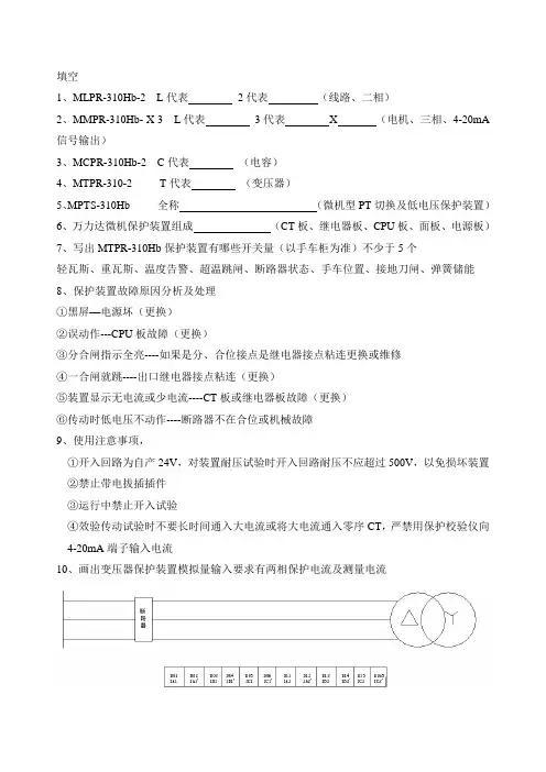
10、画出变压器保护装置模拟量输入要求有两相保护电流及测量电流。
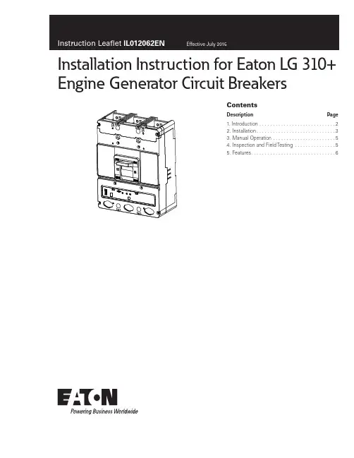
ContentsDescription Page 1. Introduction ............................22. Installation .............................33. Manual Operation .......................54. Inspection and Field Testing ...............55. Features . (6)Installation Instruction for Eaton LG 310+Engine Generator Circuit Breakers2Instruction Leaflet IL012062ENEffective July 2015Installation Instruction for Eaton LG 310+Engine Generator Circuit BreakersEATON WARNINGCONTACT WITH ENERGIZED EQUIPMENT CAN RESULT IN DEATH, SEVERE PERSONAL INJURY, OR SUBSTANTIAL PROPERTY DAMAGE. DO NOT ATTEMPT TO INSTALL OR PERFORM MAINTENANCE ON EQUIPMENT WHILE IT IS ENERGIZED. ALWAYS VERIFY THAT NO VOLTAGE IS PRESENT BEFORE PROCEEDING THE TASK, AND ALWAYS FOLLOW GENERALLY ACCEPTED SAFETY PROCEDURES.EATON IS NOT LIABLE FOR THE MISAPPLICATION OR MISINSTALLATION OF ITS PRODUCTS.The user is cautioned to observe all recommendations, warnings, and cautions relating to the safety of personnel and equipment as well as all general and local health and safety laws, codes, and pro-cedures. The recommendations and information contained herein are based on Eaton experience and judgement, but should not be considered to be all-inclusive or covering every application or circum-stance which may arise. If any questions arise, contact Eaton forfurther information or instructions.Figure 1. LG 310+ Engine Generator Circuit Breaker.1. IntroductionAs component leader for engine generator applications, Eaton pro-vides circuit breakers for original equipment manufacturers (OEMs) who produce engine generator sets, paralleling gear and transfer switchgear, as well as system integrators who provide engine gen-erator packages. Typical applications include diesel generator sets and portable or temporary power units providing a range of power ratings. Engine generator applications rely on circuit breakers to pro-vide circuit protection for valuable assets and to keep critical facilities and processes running.Eaton circuit protection solutions enable:• Reliable operation • Robust performance •Enhanced safety1.1 General InformationThe L -frame Series C circuit breaker (see Figure 1) type LG is a 600 Vac maximum rated device with an electronic 310+ RMS trip unit rated 600 A maximum for continuous current. Molded case circuit breakers are listed in accordance with Underwriters Laboratories, Inc. Standard UL 489.This instruction leaflet (IL) gives procedures for installation and field testing of L -frame Series C circuit breakers.3Instruction Leaflet IL012062ENEffective July 2015Installation Instruction for Eaton LG 310+ Engine Generator Circuit BreakersEATON 2. InstallationThe installation procedure consists of inspecting the circuit breaker and, as applicable, installing accessories, and terminals; mounting the circuit breaker; connecting the line and load conductors; torqu-ing terminals; and attaching terminal shields. Circuit breaker frames with trip units, accessories, mounting hardware, and unmounted terminals may be supplied in separate packages. To install the circuit breaker, perform the following steps.otee:N Internal accessory installation in any type of circuit breaker should be done before the circuit breaker is mounted and connected. Refer to individual accessory instruction leaflets for specific installation instructions on field installable accessories.Step 1. Compare name plate data with existing equipment ratings and system requirements to make sure that the circuit breaker is suitable for the intended installation. Prior to mounting, confirm that the circuit breaker has not been damaged during transit or initial handling.Step 2. To install any internal accessories, remove installed cover screws and cover.otee:N The circuit breaker handle must be in the tripped or OFF position to remove the cover. Instructions for installing the trip unit and accessories are supplied with the devices.Step 3. If not already installed, mount accessories (if required) in circuit breaker frame.otee:N When required to be removed or replaced, stationary interphase bar-riers can only be installed or removed with circuit breaker in the tripped or open position.Step 4. After any internal accessories are installed, and with the cir-cuit breaker in the tripped position, make sure that stationary inter-phase barriers are properly installed in base. Install cover and secure with pan-head screws. Eight screws are used for two and three pole circuit breakers. Torque to 20-22 Ib-in (2.26-2.49 N.m.).Step 5. If not already installed, mount wire connecting terminals as shown in Figure 2. Secure the terminals to the circuit breaker using two pan-head slotted screws and lock washers. Torque to 6 to 8 Ib-ft (8.14 to 10.85 N·m). With the circuit breaker mounted and before the conductors are installed and conductor clamping screws inserted, the terminal mounting screws may be checked for correct torque.WARNINGTHE VOLTAGES IN ENERGIZED EQUIPMENT CAN CAUSE DEATH OR SEVERE PERSONAL INJURY. BEFORE MOUNTING THE CIRCUIT BREAKER IN AN ELECTRICAL SYSTEM, MAKE SURE THERE IS NO VOLTAGE PRESENT WHERE WORK IS TO BE PERFORMED. SPECIAL ATTENTION SHOULD BE PAID TO REVERSE FEED APPLICATIONS TO ENSURE NO VOLTAGE IS PRESENT.Figure 2.LDorPan -Head Screws Pan -Headand Lockwashers (Installed beforeT erminal Installationotee:N Depending on the equipment configuration, the circuit breaker can be mounted using different styles of hardware. The following steps describe how to mount the circuit breaker using standard hardware. When special hard-ware is needed (for example, with the motor operator), the instruction leaflet describing the accessory also describes the special mounting arrangements.Step 6. To mount the circuit breaker, perform the following steps:a. For individual surface mounting, drill mounting panel usingthe drilling plan shown in Figure 3. For panel board mounting, only load end support mounting holes are required. For dead front cover applications, cut out cover to correct escutcheon dimensions (see Figure 4).b. If circuit breaker includes factory or field installed internalaccessories, make sure accessory wiring is accessible when the circuit breaker is mounted.otee:N Labels with accessory connection schematic diagrams are provided on the side of the circuit breaker.c. Position circuit breaker on mounting surface.d. Install circuit breaker mounting screws and washers. Tightenscrews firmly, but do not exceed 28 Ib-in (3 N·m).Installation Instruction for Eaton LG 310+Engine Generator Circuit Breakers EATONFigure 4. Circuit Breaker Escutcheon Cutout Dimensions.Figure 5.TerminalShieldScrewsInstallation of T erminal Shields and Warning Label.CAUTIONWHEN ALUMINUM CONDUCTORS ARE USED, THE APPLICATION OFA SUITABLE JOINT COMPOUND IS RECOMMENDED TO REDUCE THEPOSSIBILITY OF TERMINAL OVERHEATING. OVERHEATING CAN CAUSENUISANCE TRIPPING AND DAMAGE TO THE CIRCUIT BREAKER.Step 7. Connect line and load conductors and accessory.Step 8. After the circuit breaker is installed, check all mounting hard-ware and terminal connecting hardware for correct torque loading.Torque values for line/load terminals are given in Table 1 and on thecircuit breaker nameplate.Step 9. Install line terminal cover on circuit breaker cover withmounting screws provided. Torque to 20-22 lb-in. (2.26-2.49 N·m).Step 10. When step-type terminals (Cat. No. TA603LD or TA401LD)are used, terminal shields (supplied with terminals) must be installedon the circuit breaker (see Figure 5) and secured using retainer andscrews included with the terminal shield kit. Warning label suppliedwith the kit must be attached to the circuit breaker cover.WARNINGHAZARDOUS VOLTAGE CONDITIONS CAN CAUSE DEATH OR SEVEREPERSONAL INJURY. MAINTAIN ORIGINAL ELECTRICAL CLEARANCE ANDCREEPAGE SPACINGS AT TERMINATIONS.45Instruction Leaflet IL012062ENEffective July 2015Installation Instruction for Eaton LG 310+ Engine Generator Circuit BreakersEATON 3. Manual OperationWARNINGCONTACT WITH ENERGIZED EQUIPMENT CAN RESULT IN DEATH, SEVERE PERSONAL INJURY, OR SUBSTANTIAL PROPERTY DAMAGE. DO NOT ATTEMPT TO INSTALL OR PERFORM MAINTENANCE ON EQUIPMENT WHILE IT IS ENERGIZED. ALWAYS VERIFY THAT NO VOLTAGE IS PRESENT BEFORE PROCEEDING WITH THE TASK, AND ALWAYS FOLLOW GENERALLY ACCEPTED SAFETY PROCEDURES.otee:N When replacing an existing circuit breaker of the types listed, make sure the voltage, continuous current, and interrupting rating of the new circuit breaker are suitable.Manual operation of the circuit breaker is controlled by the circuit breaker handle and the PUSH-TO-TRIP button in the trip unit. The circuit breaker handle has three positions, two of which are shown on the cover with raised lettering to indicate ON and OFF .On the handle, ON, OFF , and trip are also shown by a color-coded strip for each circuit breaker handle position: red for ON, white for tripped, and green for OFF (see Figure 6).3.1 Circuit Breaker ResetAfter a trip operation, the circuit breaker is reset by moving the cir-cuit breaker handle to the Reset (extreme OFF) position.otee:N In the event of a thermal (overload) trip, the circuit breaker cannot be reset immediately. A circuit breaker with a DIGITRIP 310+ RMS trip unit simulates the thermal element of a thermal-magnetic type trip unit with an electronic “thermal memory“ that also requires up to five minutes to “cool” before it can be re-energized. No circuit breaker should be reclosed until the cause of trip is known and the situation rectified.3.2 PUSH-TO-TRIP ButtonThe PUSH-TO-TRIP button operates the circuit breaker tripping func-tion and may be used to periodically exercise the operating mecha-nism.Figure 6. Circuit Breaker Manual Controls.4. Inspection and Field TestingSeries C molded case circuit breakers are designed to provide years of almost maintenance-free operation. The following proceduredescribes how to do a limited amount of field inspection and testing of a circuit breaker.4.1 InspectionCircuit breakers in service should be inspected periodically. The inspection should include the following checks 1 through 8.WARNINGTHE VOLTAGES IN ENERGIZED EQUIPMENT CAN CAUSE SEVERE PERSONAL INJURY OR DEATH. BEFORE INSPECTING THE CIRCUITBREAKER IN AN ELECTRICAL SYSTEM, MAKE SURE THE CIRCUIT BREAKER IS SWITCHED TO THE OFF POSITION AND THAT THERE IS NO VOLTAGE PRESENT WHERE WORK IS TO BE PERFORMED. PAY SPECIAL ATTENTION TO REVERSE FEED APPLICATIONS TO ENSURE NO VOLTAGE IS PRESENT.CAUTIONSOME COMMERCIAL CLEANING AGENTS WILL DAMAGE THENAMEPLATES OR MOLDED PARTS. MAKE SURE THAT CLEANING AGENTS OR SOLVENTS USED TO CLEAN THE CIRCUIT BREAKER ARE SUITABLE FOR THE JOB.Step 1. Remove dust, dirt, soot, grease, or moisture from the sur-face of the circuit breaker using a lint-free dry cloth, brush, or vacu-um cleaner. Do not blow debris into circuit breaker. If contamination is found, look for the source and eliminate the problem.Step 2. Switch circuit breaker to ON and OFF several times to be sure that the mechanical linkages operate freely and do not bind. If mechanical linkages do not operate freely, replace circuit breaker.Step 3. With the circuit breaker in the ON position, press the PUSH-TO-TRIP button to mechanically trip the circuit breaker. Trip, reset, and switch circuit breaker ON several times. If the mechanism does not reset each time the circuit breaker is tripped, replace the circuit breaker.Step 4. Check base, cover, operating handle, and handle barrier for cracks, chipping, and discoloration. Circuit breakers should be replaced if cracks or severe discoloration is found.Step 5. Check wire connecting terminals and other type bus bar connectors for looseness or signs of overheating. Overheating will show as discoloration, melting, or blistering of conductor insulation, or as pitting or melting of conductor surfaces due to arcing. If there is no evidence of overheating or looseness, do not disturb or tighten the connections. If there is evidence of overheating, terminations should be cleaned or replaced. Before re-energizing the circuit break-er, all terminations and cable should be refurbished to the originally installed condition.Step 6. Check circuit breaker mounting hardware, and tighten if nec-essary.Step 7. Exposure to certain types of chemicals can cause deteriora-tion of electrical connections. Check area where circuit breaker is installed for any safety hazards, including personal safety and fire hazards and take required precautionary actions.Step 8. The operation of circuit breakers with 310+ trip units can be field tested periodically using the Electronic test kit (See IL5721B13H05).4.2 Field T estingAny field testing should be done in accordance with applicable NEMA Standard.310+ Trip UnitInternational Symbols - ON - OFFHandle Position Indicator Color Red - ON White - TRIPGreen - OFF (Reset)Push-to-TripButton6EATON FILE = 6636C85_Rev-5DATE = 05/12/15S# 6636C85H32BAR CODE = 1066368532See Fig. 13Figure 8. Instantaneous T rip Settings.5. Features1. Remote Maintenance Mode (RMM) - OptionalAn option that allows a user to remotely lower the instantaneous pickup of the breaker to 2.5x the frame rating (In), and to bypass any programmed delays (tsd or tg). The purpose of the function is to reduce incident energy during a fault condition.For example, a 600A (In) LG breaker with the switch set to 2.5x would trip instantaneously when the current exceeded 1500 A. The RMM is enabled by applying 24VDC to the two wire cable that exits the left side of the breaker. The wires are color coded Y ellow (+24V) and Black (common ground) - (see Figure 9). A blue colored LED on the trip unit lights when the breaker is in RMM (see Figure 7).The lighted blue LED indicates that RMM is enabled. This setting corresponds to 2.5x of In. Turning the Isd switch on the trip unit has no effect on either the Maintenance Mode or the tsd\tg set-tings while the blue LED is lit.Also, a relay contact closure indicates that the RMM has been enabled. The blue and red wires are the C and NO contacts of this relay. The relay has a dual function: 1) enable RMM and 2) provide a contact closure indication that RMM is enabled.Both the yellow and black set of wires and the red and blue set of wires exit on the left side of the breaker.otee:N The RMM contacts are rated at 2A at 30 VDC and 0.5A at 125 VAC.no trip indicator when using the test port. In normal modes, the red LED indicates a high load alarm. For a high load alarm, it will blink ON-OFF if the continuous current is 105% of the Ir setting and is present for a duration over 38 seconds.3. High Load Alarm Relay - OptionalThis option will provide a SPST contact closure when the trip unit current equals or is greater than 105% of In for a period of 38 seconds. If the current drops below the 105% value, the contact will open. The yellow and green wires that exit the right side of the breaker are the common (C) and normally open (NO) of this relay (see Figure 10).Settings A = 500A B = 600A C = 800A D = 1000AE = 1250AF = 1500AG = 2000AH = 2500A7Instruction Leaflet IL012062ENEffective July 2015Installation Instruction for Eaton LG 310+ Engine Generator Circuit BreakersEATON Figure 10. GRN YELALARM RELAY12D7NRD40041+10-3W12NC14NO18W29NC27NO2K2CONT 2A 24VDC TQ2SA-24VJ7-7J7-8High Load Alarm Relay Wiring Diagram.T able 1. T erminal T ypesTerminal Cat. No. @Terminal Material BodyScrew Head TypeAWG Wire RangeWire TypeTorqueValue Lb-in (N.m)TA602LD Aluminum Socket 310-350 Cu/Al 275 (31.1)TA603LDKAluminum Socket 400-500 Cu/Al 275 (31.1)T602LD Copper Socket 250-350 Cu 275 (31.1)TA401LDK e AluminumSocket 410-600Cu/Al 400 (45.2)TA450LDAluminumSocket4-4/0Cu/Al275 (31.1)The maximum width non-standard wire connector (tang-type) or bus bar connector that can be usedwithout reducing electrical clearance and creepage distances between phases is 1.690 in. (42.93 mm).No hardware or connector should be installed in a manner to reduce the electrical clearancebetween the underneath side of the phase termination (line or load) and ground without the addi-tion of supplementary insulation.Sold in 2-, 3-, and 4-pole kits only (2TA603LDK/3TA603LDK/4TA 603LDK). All terminals can accommodate two cables, except TA 401LD.e Sold in 2-, 3-, and 4-pole kits only (2TA401LDK/3TA401LDK/4TA401LDK).Eaton1000 Eaton Boulevard Cleveland, OH 44122 United States © 2015 EatonAll Rights ReservedPrinted in USAPublication No. IL012062EN / TBG 1235 Part Number: IL012062ENH01July 2015Eaton is a registered trademark.All other trademarks are propertyof their respective owners. Installation Instruction for Eaton LG 310+ Engine Generator Circuit BreakersInstruction Leaflet IL012062ENEffective July 2015Disclaimer of Warranties and Limitation of LiabilityThe information, recommendations, descriptions, and safety nota-tions in this document are based on Eaton experience and judg-ment, and may not cover all contingencies. If further information is required, an Eaton sales office should be consulted.Sale of the product shown in this literature is subject to the terms and conditions outlined in appropriate Eaton selling poli-cies or other contractual agreement between Eaton and the purchaser.THERE ARE NO UNDERSTANDINGS, AGREEMENTS, WARRANTIES, EXPRESSED OR IMPLIED, INCLUDING WARRANTIES OF FITNESS FOR A PARTICULAR PURPOSE OR MERCHANTABILITY, OTHER THAN THOSE SPECIFICALLY SET OUT IN ANY EXISTING CONTRACT BETWEEN THE PARTIES. ANY SUCH CONTRACT STATES THE ENTIRE OBLIGATION OF EATON. THE CONTENTS OF THIS DOCUMENT SHALL NOT BECOME PART OF OR MODIFY ANY CONTRACT BETWEEN THE PARTIES.In no event will Eaton be responsible to the purchaser or user in contract, in tort (including negligence), strict liability, or otherwise for any special, indirect, incidental, or consequential damage or loss whatsoever, including but not limited to damage or loss of use of equipment, plant or power system, cost of capital, lossof power, additional expenses in the use of existing power facili-ties, or claims against the purchaser or user by its customers resulting from the use of the information, recommendations, and descriptions contained herein.The information contained in this manual is subject to change without notice.。

微机继电保护测试仪特点与技术参数第一节主要特点◆标准的4相电压3相电流输出具有4相电压3相电流输出,可方便地进行各种组合输出进行各种类型保护试验。
每相电压可输出120V,电流三并可输出120A,第4相电压Ux为多功能电压项,可设为4种3U0或检同期电压,或任意某一电压值的情况输出。
◆单机操作方便单机由方便灵活的旋转鼠标通过大屏幕液晶显示屏进行操作,全部中文显示。
可完成现场大多数试验检定工作,可对各种继电器及微机保护进行检定,并可模拟各种复杂的瞬时性、永久性、转换性故障进行整组试验。
开机即可使用,操作方便快捷。
◆双操作方式,联接电脑运行通过WiDYows平台上的全套中文操作软件,可进行各种大型复杂及自动化程度更高的校验工作,可方便地测试及扫描各种保护定值,可实时存贮测试数据,显示矢量图,绘制故障波形,联机打印报表等。
◆软件功能强大可完成各种自动化程度高的大型复杂校验工作,如三相差动试验、厂用电快切、备自投试验、线路保护检同期重合闸等,能方便地测试及扫描各种保护定值,进行故障回放,实时存储测试数据,显示矢量图,联机打印报告等。
◆开关量接点丰富DY-802为7路接点输入和2对空接点输出。
输入接点为空接点和0~250V电位接点兼容,可智能自动识别。
输入、输出接点可根据用户需要扩展。
◆大屏幕LCD显示屏本机采用320×240点阵大屏幕高分辨率图形液晶显示屏,全部操作过程均在显示屏上设定,操作界面和试验结果均汉化显示,显示直观清晰。
◆自我保护采用合理设计的散热结构,并具有可靠完善的多种保护措施及电源软启动,和一定的故障自诊断及闭锁功能。
◆具有独立专用直流电源输出装置设有一路110V 及220V专用可调直流电源输出。
◆性价比高属于跨专业联合设计产品,综合了多专业的先进科技成果。
兼具大型测试仪的性能,和小型测试仪的价位,具有很高的性能价格比。
第二节额定参数交流电流输出输出精度0.2级相电流输出(有效值)0~40A三并电流输出(有效值)0~120A相电流长时间允许工作值(有效值)10A相电流最大输出功率420VA三并电流最大输出时最大输出功率900VA三并电流最大输出时允许工作时间10s频率范围(基波)20~1000Hz谐波次数1~20 次直流电流输出输出精度0.2级电流输出0~±10A / 每相,0~±30A / 三并最大输出负载电压20V交流电压输出输出精度0.2级相电压输出(有效值)0~120V线电压输出(有效值)0~240V相电压/线电压输出功率80VA / 100VA频率范围(基波)20~1000Hz谐波次数1~20次直流电压输出输出精度0.5级相电压输出幅值0~±160V线电压输出幅值0~±320V相电压/线电压输出功率70VA / 140VA第二章装置硬件结构第一节装置硬件组成控制数字信号处理器微机本装置采用高速、高性能数字控制处理器作为控制微机,软件上应用双精度算法产生各相任意的高精度波形。
0HL-012-025说明书上海华建电力设备有限公司1. 概述LL-300、LL-310微机电动机保护监控装置适用于380V 低压系统,作为配出馈线终端的保护、监测和控制的新一代智能化综合装置。
除了保护、监控功能,LL-300、LL-310系列还提供了设备维护和运行的记录、跳闸记录以及额定参数等重要信息,为现代化的设备管理带来很大的便利。
2. 特点● 交流采样,测量A 、B 、C 三相电流,自动计算零序电流,不需要外加零序互感器 ● 保存三次故障跳闸记录● LL-300系列显示屏为中文液晶,LL-310系列为LED 数码管显示 ● 4个开关量输入,装置面板上有信号灯指示。
● 提供外部跳闸的开关量输入 ● 具有远方控制接点,可实现遥控功能● 对模拟量输入,开关量输入和输出模件,其内部具有完善的电气和安全隔离 ● 硬件和软件的连续自我检测,以取得最大的可靠性● 采用RS485通信总线,可广泛用于各种监控系统作为带有马达控制的智能化监控单元3. 主要功能保护功能: 过电流、零序过电流测量功能:三相电流、零序电流的测量和显示 辅助功能: ● 状态量监测 ● 外部跳闸● 事故发生时自动记录事故类型和数据,共保存三次事故记录采集标准CT 输入,可选额定输入1A 或5A自带精密互感器,可选额定电流为1A 、5A 、10A 、25A 、50A 、100A 、160ALL-300系列LL-310系列4.型号说明L L — 3 □□□—□额定电流LL-300系列:1A或5ALL-310系列:1A、5A、10A、25A、50A、100A、160A功能号见功能表功能号0:无遥控1:带遥控功能装置结构形式0:装置不带CT1:装置自带CT设计序号产品型号举例说明:LL-301D -1A表示LL-300系列,带状态量输入及遥控功能,具有通讯功能,额定电流输入1A5.技术数据5.1.输入/输出LL-300系列的模拟量输入回路额定电流In1A或5A额定频率Fn50Hz功率消耗:CT回路每相当In=1A时≤0.20VA当In=5A时≤0.75VA过载能力CT回路2In,连续工作10In ,10s30In ,1sLL-310系列的模拟量输入回路额定电流In1、5、10、25、50、100、160A可选额定频率Fn50HzCT回路功率消耗无CT回路连接方式馈电电缆直接穿过设备的3个预制孔过载能力CT回路随馈电电缆的过载能力而定辅助电源交直流通用电源80V-250V.AC或90V-250V.DC功耗正常工作时≤3W保护启动时≤5W辅助电源允许中断时间300ms继电器输出跳闸继电器R1 1常开常闭转换接点(报警输出)跳闸继电器R2 1常开接点(保护动作输出)合闸继电器R3 1常开接点(遥控合闸输出)输出容量AC250V 7ADC30V 7A开关量(二进制)输入开关量输入数目4个电压范围24VDC±20%波纹系数≤5%电流消耗约2.5mA串行接口连接通信端子规约企业规约网络连接RS485总线,屏蔽双绞线5.2.环境条件允许温度工作-10℃~+55℃储存-25℃~+70℃允许湿度相对湿度≤95% 无凝结5.3.电气试验绝缘电阻标准IEC255-5 100MΩ/500V绝缘试验标准 IEC255-5介质强度试验2kV(r.m.s.),50Hz,1min冲击电压试验5kV(峰);1.2/50μS;0.5J;3正,3负,间隔时间5sEMC抗干扰标准 IEC255-22共模干扰 2.5kV(峰),1MHz,400次/s持续时间2s差模干扰 1.0kV(峰),100kHz,50次/s持续时间2s辐射电磁场干扰频率:27MHz~1000MHz;场强:10V/m 静电放电干扰8kV快速瞬变干扰2kV;5kHz;双极性;持续时间1min 6.保护特性与设定范围6.1.零序过流保护—自动计算零序电流,不需要外接零序互感器。
μMPS4000系列变电站综合自动化系统μMPS4000-310B、320B微机遥测遥控保护装置技术及使用说明书V6.3北京清大华康电子技术有限责任公司二零零六年三月目录目录 (1)1.概述 (2)2.μMPS 4310B/320B主要功能 (3)3.主要技术要求和指标 (3)3.1工作环境条件 (3)3.2周围环境 (3)3.3电源 (3)3.4主要技术参数 (4)4.装置原理及功能说明 (5)4.1输出操作 (5)4.2交流电量测量 (5)4.3 操作记录和SOE记录 (5)4.4测量通道的软件校正处理 (5)4.5硬件说明 (5)4.6操作回路 (8)5.测量参数与参数说明 (9)5.1测量参数表说明 (9)5.2系统参数表说明 (10)6.装置结构与接线端子图 (10)6.1结构外形 (10)6.2面板按键与指示灯操作说明 (12)6.3后面板端子接线说明 (13)7.面板显示操作功能说明 (15)7.1屏幕显示操作功能一览表 (15)7.2系统信息显示 (15)7.3主屏幕显示 (15)7.4一级菜单 (16)7.5系统信息显示 (16)7.6常规显示 (16)7.7设置 (18)7.8记录查询 (20)7.9系统参数查询 (22)7.10输出操作 (22)7.10测量校正 (23)1.概述μMPS 4000系列综合自动化系统是的新一代面向二十一世纪的变电站成套保护装置。
μMPS 4000系列变电站综合自动化系统由如下产品构成:μMPS 4100系列线路保护装置μMPS 4110 微机线路保护装置μMPS 4120微机电容保护装置μMPS 4130微机方向线路保护装置μMPS 4140微机零序距离线路保护装置μMPS 4150微机横差电流方向线路保护装置μMPS 4160微机母线差动保护装置μMPS 4200系列主设备保护装置μMPS 4210 微机双绕组变压器差动保护装置μMPS 4220微机三绕组变压器差动保护装置μMPS 4230微机变压器后备保护装置μMPS 4240微机发电机差动保护装置μMPS 4250微机发电机后备保护装置μMPS 4260微机电动机差动保护装置μMPS 4270微机电动机保护装置μMPS 4280微机厂(站)用变保护装置μMPS 4290微机解列保护装置μMPS 4300系列测控装置μMPS4310 微机遥测遥控装置μMPS4320 微机遥信遥控装置μMPS4330 微机遥调装置μMPS4340 微机自动准同期装置μMPS4350 微机备自投装置μMPS4360 微机PT切换装置μMPS4370 微机脉冲电度测量装置μMPS4380 微机多功能变送测量装置μMPS4390 微机解列装置μMPS 4400系列管理装置单元μMPS4410 通信装置μMPS4420 管理单元μMPS4430 双机管理单元μMPS 4310B微机遥测遥控装置主要用于6kV~110kV的线路遥测和遥控,而μMPS 4320B微机遥控遥信装置主要用于断路器的遥信和遥控,其主要特点是:l 采用多CPU和并行数据采集及处理技术,精度高;l 采用宽温带背光240×128大屏幕LCD显示器,方便显示和操作;l 可选择采用RS 232和CAN方式,支持多种远动传输规约,方便与各种管理系统连接;l 集成度高、体积小、重量轻,便于集中和分散安装。

ContentsDescription Page Section 1: General Information . . . . . . . . . . . . . .2Section 2 . Trip Unit Installation . . . . . . . . . . . . . . .2Section 3 . Trip Unit Controls and Functions . . . . .5Section 4 . Neutral Current Sensor Information . . .7Section 5 . 100% Rated LD and MDL FrameCircuit Breakers . . . . . . . . . . . . . . . . . .7Instruction Leaflet for theLES/MES 310+ Electronic Trip Unit2Instruction Leaflet IL012043ENEffective January 2016Instruction Leaflet for theLES/MES 310+ Electronic T rip UnitEATON WARNINGDO NOT ATTEMPT TO INSTALL OR PERFORM MAINTENANCE ON EQUIP-MENT WHILE IT IS ENERGIZED. DEATH OR SEVERE PERSONAL INJURY CAN RESULT FROM CONTACT WITH ENERGIZED EQUIPMENT. ALWAYS VERIFY THAT NO VOLTAGE IS PRESENT BEFORE PROCEEDING.Section 1: General InformationT able 1. Parts ListL OR M 310+ ELECTRONIC TRIP UNIT IL FOR 310+ ELECTRONIC TRIP UNITSNEUTRAL CURRENT SENSOR (GROUND FAULT ONLY)NEUTRAL & ALARM LEADS (GROUND FAULT ONLY)4TH POLE CT ASSEMBLY (4 POLE ONLY)Section 2. Trip Unit InstallationStep 1Remove the 8 screws (10 for MDL -frame) holding the base and cover together (Figure 1) .Figure 1. LES Base-cover Screws.Step 2Remove the 2 retaining screws (3 for 4-pole breaker) from the shunt plate inserts in the base of the circuit breaker frame .Step 3 (4-pole Only)Plug the current sensor secondary winding connector into the recep-tacle in the side of the trip unit . Either polarity is acceptable since the secondary winding connector is not polarized .Figure 2. 4th Pole Installation.Step 4Position the retaining screws in the trip unit and current sensor con-ductor holes (Figure 3) .Figure 3. Retaining Screws Location in Trip Unit.Trip UnitSecondary Winding ConnectorCurrentSensor3Instruction Leaflet IL012043ENEffective January 2016Instruction Leaflet for theLES/MES 310+ Electronic T rip Unit EATON Figure 5. Wire Routing Cable Tie Placement.Cable TiesBreaker Frame Wiring HarnessesFigure 7. LES 4-pole T rip Unit Mounting Screw Locations.Load EndTest Port4Instruction Leaflet IL012043ENEffective January 2016Instruction Leaflet for theLES/MES 310+ Electronic T rip UnitEATON Step 7 (MES Trip Units)Starting with the center pole (mech pole), torque line side screws to 10-12 lb .-ft . (14-16 N·m) and load side screws to 6 – 8 lb .-ft . (8 – 10 N·m) (Figure 8) .Figure 8. MES T rip Unit Mounting Screw Locations.Step 8.Install any accessories, if required, using the appropriate instruction leaflet .The following types of internal accessories, which mount on the trip unit, are available for use . The number of the IL covering the installa-tion of each accessory is shown .• Alarm (Signal)/Lockout (ASL) Switch . . . . . . . . . . . . . . . . . . . . . . . . . . . . . .I .L . 29C183• Auxiliary Switch . . . . . . . . . . . . . . . . . . . . . . . . . . . . . . . . . . . . . . . . . . . . . . . . . . . . . . . . . . . . . .I .L . 29C123• Shunt Trip . . . . . . . . . . . . . . . . . . . . . . . . . . . . . . . . . . . . . . . . . . . . . . . . . . . . . . . . . . . . . . . . . . . . . . . .I .L . 29C146• Low Energy Shunt Trip . . . . . . . . . . . . . . . . . . . . . . . . . . . . . . . . . . . . . . . . . . . . . . . . . . .I .L . 29C147•Undervoltage Release Mechanism (Handle Reset) . . . . . . .I .L . 29C170Trip Unit Wire Routings with Accessories:•Alarm (Signal)/Lockout (ASL) Switch and Auxiliary Switch:From trip unit, route wiring harnesses through the recessed cen-ter portion of the accessory bracket and through the slots in the breaker frame .•Shunt Trip:From trip unit, route wiring harnesses through the recessed cen-ter portion of the accessory bracket overlapping the white and yellow accessory wires, over the shunt trip, and through the slots in the breaker frame .•Low Energy Shunt Trip and Undervoltage Release Mechanism (Handle Reset):From trip unit, route wiring harnesses under accessory bracket and through the slots in the breaker frame .Step 9Finish the installation by installing the cover on the base, as shown in Figure 10 .Figure 9. Re-attach Cover and Base of the Breaker.5Instruction Leaflet IL012043ENEffective January 2016Instruction Leaflet for theLES/MES 310+ Electronic T rip Unit EATON Figure 11. LSIG Short Delay and Ground Fault Time Settings.1 . Test Port - A test port is built into each trip unit to allow use of afunctional test kit . The test kit performs a test of the Long Delay, Short Delay and Ground Fault functions (Plug-In Test Kit Catalog #MTST230V) . Remove the test port cover prior to connecting to the test port .2 . Test/Alarm LED - A dual function, bi-color (red-amber) LED . It isused as an amber no trip indicator when using the test port . In normal modes, the red LED indicates a high load alarm . For a high load alarm, it will blink ON-OFF if the continuous current is 105% of the I r setting and is present for a duration over 38 sec-onds .3 . I r - Continuous current setting . In accordance with standardsrequirements, the trip unit initiates a trip of the circuit breaker within 2 hours for an overload of 135% and will trip as a function of l²t for higher currents . Continuous current values for each let-tered setting are indicated by the chart displayed on the left side of the trip unit label .4 . t r - The number of seconds required to trip @ 6x I r . For example,if I r = 250A, t r = 2 sec, and load current = 1500A, or 6x I r , then the breaker will trip in 2 seconds .5 . l sd - Setting in multiples of l r for short circuit conditions thatexceed the short delay pick-up setting, the trip unit initiates a trip after a predetermined delay .otee:N In addition to the short delay trip function, there is a fixed instan-taneous override for the 600A and 800A trip units . The override for the 600A is fixed at 5620A, the override for the 800A is fixed at 6800A . If a fault current exceeds these override values, the breaker will trip instanta-neously (in 20 milliseconds or less) .6 . I g - Ground fault pick-up setting . It is used on the LSIG and LSGstyles to set the ground fault pick-up as a percentage of I n (frame current) . For example, a 600A frame with an I g setting of 0 .4 will provide a ground fault pick-up at 240A .7 . t sd - for the LSI style, the short delay time is a flat responsedetermined by the tsd switch settings of INST 120ms, or 300ms . For the LS styles, the short delay time is an I²t function, with a delay of 67ms at a Isd setting of 6x .8 . t sd / t g - For the LSIG style, the short delay is a flat responsedetermined by the tsd/tg switch settings of INST 120ms or 300ms . This switch is a dual switch that also determines the ground fault time settings of INST , 120ms or 300ms . For exam-ple, if the t sd /t g switch is set at position J, then both short delay time and ground fault time are at INST flat . As another example, set the t sd /t g switch at position L; the short delay time is INST and the ground fault time is 300ms . The LSIG label (Figure 11) should be used in conjunction with the t sd /t g switch to set any one of nine possible combinations of short delay and ground fault times .9 . t g - For the LSG style, the short delay time is an I²t functionwhile the ground fault flat time is set by the t g switch .10 . Status LED - A green status light indicates the operational statusof the trip unit . If the load current exceeds approximately 20% of the maximum current rating (I n ) of the breaker, the status lightSection 3. Trip Unit Controls and FunctionsA . Trip unit controls and settings (refer to Figures 10 and 11) .Figure 10. LES / MES T rip Units Settings.I r Settings LESMESA = 250AA = 320AB = 300A B = 400AC = 315A C = 450AD = 350A D = 500AE = 400A E = 600AF = 450AF = 630AG = 500A G = 700AH = 600A = InH = 800A = In*Settings t g (ms)Inst.120300t sd(ms)Inst.J K L 120M n O 300PQR6Instruction Leaflet IL012043ENEffective January 2016Instruction Leaflet for theLES/MES 310+ Electronic T rip UnitEATON will blink on for one second and off for one second .B . Other features and options of the LES/MES 310+ trip units .1 . The High Load Alarm Relay option will provide a SPST contactclosure when the trip unit current equals or is greater than 105% of In for a period of 38 seconds . If the current drops below the 105% value, the contact will open . The yellow and green wires that exit the right side of the breaker are the common (C) and normally open (NO) of this relay (See Figure 12) .2 . The Ground Fault Alarm Only option operates in a similar fash-ion as the High Load Alarm . The SPST contact will close if the ground fault pick-up setting is exceeded and will open when below the ground fault pick-up setting . The yellow and green wires that exit the right side of the breaker are the common (C) and normally open (NO) of this relay (See Figure 12) .3 . The Ground Fault Relay option will provide a SPST contact clo-sure immediately before the breaker will trip on a ground fault over current detect . This closure is momentary (50ms) and the customer must provide the necessary external circuitry in order to latch this signal . The yellow and green wires that exit the right side of the breaker are the common (C) and normally open (NO) of this relay (See Figure 12) .otee:N The High Load Alarm Relay can be selected with LS, LSI LSG, and LSIG trip units . For the LSG and LSIG trip units, the High Load Alarm will function normally . However, if the breaker trips due to a ground fault con-dition, the relay will respond with a ground fault alarm as indicated above .The Ground Fault Alarm Only can be selected for LSG and LSIG trip units only . This selection has precedence over all other relay functions . When the Ground Fault Alarm Only is selected, the High Load Alarm Relay feature is not available .otee:N The contact ratings of the relay are: 2A at 30 VDC and 0 .5 A at 125 VAC .4 . The Zone Selective Interlock (ZSI) option provides a wired meth-od of coordinating Upstream and Downstream breakers . The coordinating signals are provided by the White\Red stripe (Z in ), White\Black stripe (Z out ), and Black (common ground) wires that exit the right side of the breaker . ZSI may be ordered on LSI and LSIG trip units .Zone Selective Interlocking is active for the short delay and the ground fault delay tripping functions . The LES/MES 310+ Trip Unit Zone Selective Interlocking feature is compatible with OPTIM and Digitrip Trip Units, including all other 310+ models on Series G: (RG, NG LG, JG) and Series C (FD and KD) breakers .Three wires exit the breaker with the following color code and function: White/Black Stripe=Zone Out, White/Red Stripe=Zone In, and Black=Common (See Figure 12) .A typical connection for a two breaker system is accomplished by connecting the Z out wire of the downstream breaker to the Z in of the upstream breaker . The common black wires of both break-ers must also be connected .If a high current fault is sensed from the load on the down-stream breaker, both breakers will sense the fault . However, the downstream breaker will send the interlock signal to the upstream breaker informing it not to trip . This delay allows the downstream breaker to clear the fault without the upstream breaker tripping .However, if for some reason the downstream breaker does not clear the fault in the set delay time, the upstream breaker will then clear the fault at or before its defined t sd or t g .Multiple breakers may be connected in a system to create a zone of protection . For faults outside the zone of protection, the trip unit of the circuit breaker nearest the fault sends an inter-locking signal (Z out ) to the trip unit of the up-stream circuit break-er . (Z in ) This interlocking signal restrains immediate tripping of the upstream circuit breaker until its programmed coordination time is reached . Thus zone selective interlocking applied correctly can reduce damage due to circuit or ground fault conditions . A table of the settings of the two breakers with the respective outcomes (Both Trip or Downstream (Dn) Trips) of the breakers is indicated below for the conditions mentioned in the table head-ing .UpstreamINST120ms 300ms D o w n s t r e a mINST Both Dn 43ms Dn 43ms 120ms Both Dn 52ms Dn 52ms 300msBothDn 43msDn 43msotee:N A single breaker with the Zone Selective Interlocking feature enabled will not trip at the programmed time settings, unless Self Interlocked . That is, the Z out wire should be connected to the Z in wire .5 . Remote Maintenance Mode (RMM) is an option that allows auser to remotely lower the instantaneous pickup of the breaker to 2 .5x the frame rating (I n ), and to bypass any programmed delays (t sd or t g ) . The purpose of the function is to to reduce inci-dent energy during a fault condition . For example, a 600A (I n ) LD breaker with the switch set to 2 .5x would trip instantaneously when the current exceeded 1500 A .The RMM is enabled by applying 24VDC to the two wire cable that exits the left side of the breaker . The wires are color coded Y ellow (+24V) and Black (common ground) - see Figure 14 . A blue colored LED on the trip unit lights when the breaker is in RMM (Figure 13) .The lighted blue LED indicates that RMM is enabled . This setting corresponds to 2 .5x of I n . Turning the I sd switch on the trip unit has no effect on either the Maintenance Mode or the t sd \t g set-tings while the blue LED is lit .Also, a relay contact closure indicates that the RMM has been enabled . The blue and red wires are the C and NO contacts of this relay . The relay has a dual function: 1) enable RMM and 2) provide a contact closure indication that RMM is enabled .Both the yellow and black set of wires and the red and blue set of wires exit on the left side of the breaker .otee:N The RMM contacts are rated at 2A at 30 VDC and 0 .5A at 125 VAC .7Instruction Leaflet IL012043ENEffective January 2016Instruction Leaflet for theLES/MES 310+ Electronic T rip Unit EATON Figure 12. Alarm, ZSI, and Neutral Wiring Diagram.GRN YELBLKWHI/BLK STRIPEN.C.WHI/RED STRIPEGRYWHIALARM ZSIRELAYCABLENEUTRAL12D7NRD40041+10-3W12NC14NO18W29NC27NO2K2CONT 2A 24VDC TQ2SA-24VJ7-38-POS "PHD" RAJ7-1J7-5J7-7J7-8J7-2J7-6J7-4ZOUTZINSection 4. Neutral Current Sensor Informa-tion.Ground fault trip units are supplied from the factory with pigtail lead connections for a neutral current sensor (white and grey wires) . A neutral current sensor shown in Figure 14 is available . 310+ Ground Fault Trip Units detect ground fault currents through Residual Sensing . They are not designed to use source ground or zero sequence ground fault sensing methods . If the system neutral is grounded, but no phase to neutral loads are used, the neutral cur-rent sensor is not necessary . In that case, the white and grey leads on the trip should be cut off before installation . If the system neutral is grounded and phase to neutral loads are used, then the neutral current sensor must be used . It should be connected to the breaker according to Figure 15 It has the same turns ratio as the phase cur-rent sensors in the trip unit .NOTICETHE POLARITY OF THE SENSOR CONNECTIONS IS CRITICAL. ALWAYS OBSERVE THE POLARITY MARKINGS ON THE INSTALLATION DRAW-INGS. THE POLARITY MARKINGS ARE IDENTIFIED AS WHITE DOTS ON THE TRANSFORMERS. TO INSURE CORRECT GROUND FAULT EQUIPMENT PERFORMANCE, CONDUCT FIELD TESTS TO COMPLY WITH NATIONAL ELECTRIC CODE REQUIREMENTS UNDER ARTICLE 230-95-C.otee:N See wiring instructions below for special restrictions on accessory wir-ing for ground fault breakers . Then install the ground fault alarm and neutral current sensor connector printed circuit board as described previously .CAUTIONLEADS COULD BE DAMAGED IF IN CONTACT WITH MOVING PARTS. ACCESSORY WIRES SHOULD BE FORMED AND ROUTED TO CLEAR ALL MOVING PARTS.Leads to be routed:1 .2 leads (white and grey) for the neutral current sensor .2 . 2 leads (yellow and green) for the ground fault alarm relay It is not possible to have leads exiting the breaker on the opposite side . For rear exiting leads, thread the leads through the wiring troughs/tunnels in the side of the circuit breaker case . For side exiting leads, use the slots in the side of the case . Use the center trough or slot for the neutral current sensor leads (white and grey) and the trough or slot closest to the trip unit for the alarm leads (yel-low and green) .Any other leads to be brought out should then be threaded through the wiring trough closest to the trip unit .Section 5. 100% Rated LD and MDL Frame Circuit BreakersCLD, CHLD, CLDC, CMDL, and CHMDL circuit breakers are suitable for continuous operation at 100% of the frame rating if used with CU only 90° C insulated wire and AL9CU terminals in an enclosure which measures at least 24” high x 15” wide x 6” deep for the LD and 42" high x 18" wide x 7 .5" deep for the MDL . Ventilation is not required in an enclosure having these minimum dimensions .EatonElectrical Sector1000 Eaton Boulevard Cleveland, OH 44122United States877-ETN-CARE (877-386-2273) © 2016 EatonAll Rights ReservedPrinted in USAPublication No. IL012043EN / TBG001166 Part Number: IL012043ENH03 January 2016Eaton is a registered trademark.All other trademarks are property of their respective owners.Instruction Leaflet IL012043EN Effective January 2016Instruction Leaflet for the LES/MES 310+ Electronic T rip UnitFigure 15. Neutral and Alarm Wiring Diagram.The information, recommendations, descriptions, and safety nota-tions in this document are based on Eaton’s experience and judg-ment with respect to Retrofitting of Power Breakers . This instruction-al literature is published solely for information purposes and should not be considered all-inclusive . If further information is required, you should consult an authorized Eaton sales representative .The sale of the product shown in this literature is subject to the terms and conditions outlined in appropriate Eaton selling policies or other contractual agreement between the parties . This literature is not intended to and does not enlarge or add to any such contract . The sole source governing the rights and remedies of any purchaser of this equipment is the contract between the purchaser and Eaton . NO WARRANTIES, EXPRESSED OR IMPLIED, INCLUDING WARRANTIES OF FITNESS FOR A PARTICULAR PURPOSE OR MERCHANTABILITY, OR WARRANTIES ARISING FROM COURSE OF DEALING OR USAGE OF TRADE, ARE MADE REGARDING THE INFORMATION, RECOMMENDATIONS, AND DESCRIPTIONS CONTAINED HEREIN. In no event will Eaton be responsible to the purchaser or user in contract, in tort (including negligence), strict liability or otherwise for any special, indirect, incidental or conse-quential damage or loss whatsoever, including but not limited to damage or loss of use of equipment, plant or power system, costof capital, loss of power, additional expenses in the use of existing power facilities, or claims against the purchaser or user by its cus-tomers resulting from the use of the information, recommendations and description contained herein .。
MLPR-301N线路保护装置检验规程1内容及适用范围本规程规定了MLPR—301N型低压线路综合管理保护装置的检验内容、检验要求及检验方法。
本规程适用于基建、生产和运行单位继电保护工作人员进行MLPR—301N型低压线路综合管理保护装置的现场检验工作。
2 引用标准下列标准所包含的条文,通过在本规程中引用而构成为本规程的条文。
本规程出版时,所示版本均为有效。
所有标准都会被修订,使用本规程的各方应探讨使用下列标准最新版本的可能性。
GB/T 7261—2000《继电器及继电保护装置基本试验方法》GB 14285—2006《继电保护和安全自动装置技术规程》GB/T 15145—2001《微机线路保护装置通用技术条件》GB 50171—1992《电气装置安装工程盘、柜及二次回路接线施工及验收规范》DL/T 478—2001 《静态继电保护及安全自动装置通用技术条件》DL/T 587—1996 《微机继电保护装置运行管理规程》DL/T 624—1997 《继电保护微机型试验装置技术条件》DL/T 769—2001 《电力系统微机继电保护技术导则》《继电保护及电网安全自动装置检验条例》《继电保护和电网安全自动装置现场工作保安规定》3 检验项目新安装检验、全部检验和部分检验的项目见表3.1。
注 1. 全部检验周期:新安装的微机保护装置1年内进行1次,以后每隔6年进行1次。
2. 部分检验周期:每隔3年进行1次。
3. 表中有“√”符号的项目表示要求进行检验。
4. 在进行6年后的全部检验时,更换逆变电源。
4 设备概况及参数4.1 装置主要性能及参数4.1.1 装置主要性能●采用高性能十六位工业微处理器,集成度高、功能强、速度快。
●三相电流、电压交流采样,完善的测控功能。
●体积小,功耗低,适宜于直接安装在开关柜上或集中组屏。
●宽温液晶汉字显示。
●抗干扰能力强:快速瞬变干扰Ⅳ级,静电放电干扰Ⅳ级,辐射电磁场干扰Ⅲ级,脉冲群干扰Ⅲ级。
线路保护整定实例降压变电所引出10KV 电缆线路,线路接线如下图所示:已知条件:最大运行方式下,降压变电所母线三相短路电流)3(max .1d I 为5500A,配电所母线三相短路电流)3(max .2d I 为5130A ,配电变压器低压侧三相短路时流过高压侧的电流)3(max .3d I 为820A 。
最小运行方式下,降压变电所母线两相短路电流)2(m in .1d I 为3966A,配电所母线两相短路电流)2(min .2d I 为3741A ,配电变压器低压侧两相短路时流过高压侧的电流)2(min .3d I 为689A 。
电动机起动时的线路过负荷电流gh I 为350A ,10KV 电网单相接地时最小电容电流c I 为15A ,10KV 电缆线路最大非故障接地时线路的电容电流cx I 为1.4A 。
系统中性点不接地。
A 、C 相电流互感器变比为300/5,零序电流互感器变比为50/5。
一、整定计算(计算断路器DL1的保护定值,仅供参考)1、瞬时电流速断保护瞬时电流速断保护按躲过线路末端短路时的最大三相短路电流整定,保护装置的动作电流A n I K K I l d jx k j dz 11160513013.1)3(max.2.=⨯⨯==,取110A 保护装置一次动作电流A K n I I jx l jdz dz 6600160110.=⨯== 灵敏系数按最小运行方式下线路始端两相短路电流来校验:2601.066003966)2(min .1<===dz d lmI I K由此可见瞬时电流速断保护不能满足灵敏系数要求,故装设限时电流速断保护。
2、限时电流速断保护限时电流速断保护按躲过相邻元件末端短路时的最大三相短路时的电流整定,则保护装置动作电流 A n I K K I l d jx k jdz 8.176082013.1)3(max .3.=⨯⨯==,取20A保护装置一次动作电流A K n I I jx l jdz dz 120016020.=⨯== 灵敏系数按最小运行方式下线路始端两相短路电流来校验:23.312003966)2(min .1>===dz d lmI I K限时电流速断保护动作时间取0.5秒。
珠海万力达电气股份有限公司MCPR-310Hb-3(2)型微机电容器保护装置用户手册文件编号:WLD[K]-JY-01-421-2004 2005年6月前言前言1.版本说明1.1硬件版本:V1.01.2软件版本:V1.11.3通讯发码表:《300系列保护装置通讯发码表》(WLD[K]-JF-01-301-2004)2.型号说明MCPR-310Hb-3型电容器保护具有A、B、C三相电流输入;MCPR-310Hb-2型电容器保护具有A、C两相电流输入。
3.引用标准《静态继电保护及安全自动装置通用技术条件》 DL 478-2001MCPR-310Hb-3(2)型微机电容器保护装置用户手册 WLD[K]-JY-01-421-20041.产品说明MCPR-310Hb-3(2)型微机电容器保护装置主要用于35KV及以下电压等级的电容器综合保护和测控。
该装置的特点:采用高档16位单片机作控制器,计算速度快,保护功能齐全,动作可靠。
具有掉电记忆芯片存储保护定值;具有掉电实时时钟;可准确记录8次保护动作信息;具有完善自检功能。
采用汉化液晶显示,通过键盘对各项菜单进行操作,操作简便,显示直观。
该装置带有高速的CAN、RS485通讯接口,所有保护动作信息可通过CAN网或RS485通讯网上传到后台计算机监控系统。
装置完成保护功能的同时把远动三遥功能集成于机箱内,保护、测量电流分别从不同CT引入,所有的保护动作信息、遥信、遥测、遥控均可通过通讯网实现。
装置内配有完善的操作箱功能,可直接对断路器进行操作。
该装置为插件式结构,体积小,接线简单,防震、防电磁干扰能力强,可组屏或直接安装于开关柜,是变电站自动化系统的理想设备。
2.功能描述2.1电流速断保护A、B、C相保护电流中任何一相的幅值大于整定值并达到整定延时保护动作于跳闸和信号。
2.2过电流保护原理同速断。
2.3零序电流保护零序电流幅值大于整定值并达到整定延时保护动作于跳闸和信号。
珠海万力达电气股份有限公司MLPR-310Hb-3(2)型微机线路保护装置用户手册文件编号:WLD[K]-JY-01-312-2004 2004年10月前言前言1.版本说明1.1硬件版本:V1.01.2软件版本:V1.01.3通讯发码表:《300系列保护装置通讯发码表》(WLD[K]-JF-01-301-2004)2.型号说明MLPR-310Hb-3型线路保护具有A、B、C三相电流输入;MLPR-310Hb-2型线路保护具有A、C 两相电流输入。
3.引用标准《静态继电保护及安全自动装置通用技术条件》 DL 478-2001MLPR-310Hb-3(2)型微机线路保护装置用户手册 WLD[K]-JY-01-312-20041.产品说明MLPR-310Hb-3(2)型微机线路保护测控装置主要用于35KV及以下电压等级的线路的综合保护和测控。
该装置的特点:采用高档16位单片机作控制器,计算速度快,保护功能齐全,动作可靠。
具有掉电记忆芯片存储保护定值;具有掉电实时时钟;可准确记录8次保护动作信息;具有完善自检功能。
采用汉化液晶显示,通过键盘对各项菜单进行操作,操作简便,显示直观。
该装置带有高速的CAN、RS485通讯接口,所有保护动作信息可通过CAN网或RS485通讯网上传到后台计算机监控系统。
装置完成保护功能的同时把远动三遥功能集成于机箱内,保护、测量电流分别从不同CT引入,所有的保护动作信息、遥信、遥测、遥控均可通过通讯网实现。
装置内配有完善的操作箱功能,可直接对断路器进行操作。
该装置为插件式结构,体积小,接线简单,防震、防电磁干扰能力强,可组屏或直接安装于开关柜,是变电站自动化系统的理想设备。
2.功能描述2.1电流速断保护A、B、C相保护电流中任何一相的幅值大于整定值并达到整定延时保护动作于跳闸和信号,可选方向元件闭锁和复合电压闭锁。
2.2限时速断保护原理同速断。
2.3过电流保护原理同速断。
2.4复合电压闭锁元件采用低电压和负序电压闭锁,以提高电流保护的灵敏度。
当系统发生三相对称短路时,系统电压会降低;当发生不对称短路时,会产生负序电压。
2.5过负荷保护A、B、C相保护电流中任何一相的幅值大于整定值并达到整定延时保护动作于信号。
2.6零序保护及小电流接地选线可采用零序电压闭锁的零序电流保护,可带零序方向。
采用分散式接地选线,由各出线保护装置和后台系统组成。
当某一出线接地后,后台根据上传信息可在画面上指出是哪一条出线接地,此功能适用于中性点不接地系统。
2.7低周减载当系统的频率下降到低周频率定值以下时,低周元件启动进行判别。
为防止系统发生负荷反馈等引起装置误动,采用欠流、欠压闭锁功能。
2.8重合闸采用三相一次重合闸,启动方式分保护跳闸启动和接点不对应启动两种,可检无压和同期。
2.9后加速当三相一次重合闸动作或手动合闸于故障线路时,加速保护跳闸。
可带延时,用以躲过电缆线路合闸时瞬间的充电电流;并可选择某些情况(速断、过流、零序、手合)与后加速相关联。
2.10PT断线的检测采用传统的判据:|UA+UB+UC|>7V时,且任两个线电压的模差大于36V时,认为PT断线;MAX{UA,UB,UC}<7V且IA>0.1In 时,认为PT三相断线。
PT断线时,将闭锁电流方向元件及复合电压闭锁元件。
2.11母充保护(用于分段保护)在手合3秒内,A、B、C相保护电流中任何一相的幅值大于整定值并达到整定延时保护动作于跳闸和信号。
手合3秒后,母充保护自行退出。
2.12低电压保护当三相线电压的最大值低于低电压整定值且断路器在合位时,并达到整定延时时保护动作于跳闸和信号。
PT断线闭锁低电压保护。
2.13故障录波记录保护三相电流、三相电压、零序电流,故障前2个周波、故障后30个周波的数据。
2.14积分电度由软件实时地将有功功率、无功功率累积成有功电度、无功电度。
3.工作原理本装置首先通过电流互感器、电压互感器将本侧保护电流、测量电流、零序电流、三相电压、零序电压输入至信号调理电路转换成对应的电压信号,然后将电压信号送至模数转换电路,由CPU读入各通道数据进行运算、处理,并与各参数整定值比较以判断线路是否发生故障,若有故障发生,则控制相应出口继电器动作,并在显示屏上显示保护动作信息,同时将保护动作信息写入掉电记忆芯片以供查询。
4.装置描述4.1显示正常运行情况下,循环交替显示保护IA1、IB1、IC1,测量IA2、IB2、IC2电流,Uab、Ubc、Uca 电压,有功功率P、无功功率Q。
在“查看”菜单项里可监视各种实时电参数。
屏幕最下一行显示提示信息:定值区号、通讯地址、重合闸充电状态、各个键的状态(是否有效)。
4.2键盘装置面板上共有8个键: 、 、 、 、确认、取消、信号复归、复位。
键:菜单选择,光标上移。
键:菜单选择,光标下移。
键:菜单选择,光标左移。
键:菜单选择,光标右移。
“确认”键:菜单确认,数据确认。
“取消”键:取消操作,返回上级菜单。
“信号复归”键:复归信号继电器,将故障显示画面恢复到正常显示画面。
“复位”键:装置复位4.3信号灯装置面板上共有信号灯6只,分别为:电源、通讯、告警信号、保护动作、装置故障。
当保护通讯正常时,“通讯”灯应该闪烁;当“装置故障”灯点亮时,说明保护装置自检发现出错。
4.4通讯接口背板串口为RS485或CAN 。
5.定值清单6.校验方法6.1校验准备6.1.1通电前检查外接线正确,外观没损坏,插件接触良好。
6.1.2上电检查合上保护电源,液晶屏幕循环显示正常运行情况下,循环交替显示保护IA1、IB1、IC1,测量IA2、IB2、IC2电流,Uab、Ubc、Uca电压,有功功率P、无功功率Q。
6.1.3装置自检在“自检”菜单项里,对装置进行自检,自检清单及说明如下:6.1.4检查开入在“开入”菜单项里,对开入回路进行检查,开入清单及说明如下:6.1.5检查开出在“开出”菜单项里,对开出回路进行检查,开出清单及说明如下:6.1.6模拟量的监测及调节在“查看”菜单项里,对模拟量进行监测,通过调节CT板上的电位器来调节显示值。
测量电流以1倍额定调准,保护电流以2倍额定调准;测量电压监视以60V调准;零序电流以1.00A 调准。
“查看”清单及说明如下:注:Hb-2型无B相保护和测量电流。
6.1.7实时时钟的设置装置内部设有掉电实时时钟,可通过通讯网实现远方校时,也可在“时钟”菜单里实现就地校时。
6.1.8故障报告的查询装置按先进先出的原则保存8次详细的事故记录,“报告”菜单就是为用户查询事故记录而设置的,当按下确认键后,则按时间从后到前的顺序显示事故记录,即第一条信息为最后一次发生的事件,这样可方便事故后的查询。
按下移键则显示上一次事故记录,连续按下移键,则可依次显示8次事故记录。
6.1.9 口令的设置口令菜单用于修改进入整定、口令、开出子菜单的口令。
初始的口令由厂家提供,万能口令为“1000”。
6.2 保护功能校验 6.2.1 速断保护定值校验按图6-1接好线,将速断电流保护投入,速断方向投入,复合电压闭锁投入。
图 6-1按下表进行整定,测量动作电流值,记入表6-1,速断动作时,测量78-79端子应导通,同时端子29-30、34-35、39-40、41-42应分别导通。
表6-1IA1’(IB1’、IC1’) IA1(IB1、IC1)UA UB UCUA ’(UB ’、UC ’)6.2.2限时速断保护定值校验按图6-1接好线。
将限时速断保护投入,限时速断方向投入,复合电压闭锁投入。
按下表进行整定,测量动作电流值,记入表6-2。
限时速断保护动作时,测量78-79端子应导通,同时端子29-30、34-35、39-40、41-42应分别导通。
6.2.3过流保护定值校验按图6-1接好线。
将过流保护投入,过流方向投入,复合电压闭锁投入。
按下表进行整定,测量动作电流值,记入表6-3。
过流保护动作时,测量78-79端子应导通,同时端子29-30、34-35、 39-40、41-42应分别导通。
6.2.4 过负荷定值校验按图6-1接好线。
将过负荷保护投入,按下表进行整定,测量动作电流值,记入表6-4。
过负荷动作时,“告警”信号灯点亮;过负荷返回时,“告警”信号灯熄灭。
6.2.5 零序电流保护定值校验按图6-2接好线,将零序电流保护和零序方向投入。
投入零序电压闭锁时,将带零序电压闭锁功能;投入零序方向时,同样带零序电压闭锁功能。
按下表进行整定,测量动作电流值,记入表6-5。
零序保护动作时,测量78-79端子应导通,同时端子29-30、29-32、34-35、34-37、39-40、41-42均应分别导通。
6.2.6 低周减载校验3U0 3U0’3I0 3I0’图6-2按图6-3接好线,将低周减载投入。
按表6-6进行整定,测量动作频率值及欠压和欠流闭锁值,记入表中。
低周动作时,测量端子78-79应导通,同时端子29-30和34-35均导通。
图 6-36.2.7 重合闸后加速校验按图6-4接好线,按下述方法进行试验。
图 6-4保护启动方式校验:将保护启动重合闸方式投入,重合闸延时整定为2.00S,将后加速所有关联项均投入,后加速延时整定为0.00S ;短接端子52、54,等待15秒后充电标识出现,加入故障电流使速断或过流保护动作,退故障电流,等待2秒后重合闸动作,再加故障电流,紧接着后加速保护动作。
接点不对应启动方式校验:当断路器跳闸而没有手动跳闸或遥控跳闸时,将启动重合闸。
将不对应启动重合闸方式投入;短接52、54端子,等待15秒后充电灯亮,断开52、54短接线(模拟断路器跳闸),等待2秒后重合闸动作。
重合闸可选择检无压和检同期,将检无压投入,当UL 电压高于检无压定值时,闭锁重合闸。
将检同期投入,同期电压方式选择相压,当UL 电压与UA 电压相位差大于检同期角度时,闭锁重合闸;同期电压方式选择线压,当UL 电压与UAB 电压相位差大于检同期角度时,闭锁重合闸。
6.2.8 手动或遥控跳闸闭锁重合闸校验将不对应启动重合闸方式投入;手动或遥控跳闸时,重合闸应不动作。
6.2.9 手动或遥控合闸到故障线路加速跳闸校验将保护出口延时整定为一个较大值,将后加速所有关联项均投入,后加速延时整定为0.00S ;手动或遥控合闸后迅速加故障电流,此时断路器应无延时跳闸。
6.2.10 PT 断线功能校验加三相对称电压,电压值大于18V ,拉掉任一相或两相,装置应报PT 断线;不加电压,加A 相电流大于0.5A ,装置应报PT 断线。
6.2.11 母充保护定值校验按图6-5接好线,1、2为A 相电流输入,3、4为B 相电流输入,5、6为C 相电流输入。
将母充保护投入。