数据采集记录仪使用说明书
- 格式:pptx
- 大小:4.35 MB
- 文档页数:14
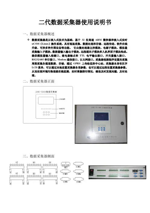
二代数据采集器使用说明书一、数据采集器概述数据采集器是以嵌入式技术为基础,基于32位高速ARM微控器和嵌入式实时uC/OS(Linux)操作系统,具有现场采集、数据处理和存储、远程传送、软件在线升级、可控多种外围设备等功能。
它由微处理器主控模块、电源子模块、模拟量采集输入子模块、数据量输入输出子模块、远程通讯子模块和人机界面子模块构成。
提供模拟量输入检测口、继电器触点和TTL电平输出接口、开关量输入接口、RS232/485串行接口、Modem通信接口、以太网接口。
采集器根据程序设置的采集周期采集各通道数据、存储,通过GPRS上传给监控中心站。
采集器本身有汉字LCD菜单,可以通过本地设置采集器各项参数,也可以通过远程设置采集器参数。
从而实现环境污染连续在线监测,实时掌握排污情况,确保及时发现问题,及时处理。
二、数据采集器正面三、数据采集器侧面四、数据采集器内部图主串口1)主控板2)模拟输入板模拟通道JP01~JP16(两脚短路是电流型,断开是电压型)3)串口板数据采集器主要组成部件说明1、模拟板:用于将外围设备输出(4-20mA)的模拟信号转成数字信号。
2、数字输入/输出板:用于数字量输入,及反控设备。
3、串口扩展板:用于连接网络,采集外围设备输出量。
4、主控板:处理外围设备输入数据,并上传给监控中心。
5、按键板:数据采集器设置输入,状态指示。
6、LCD显示屏:用来显示信息7、开关电源:给数据采集器提供稳定电源。
8、蓄电池:在停电状态下给数据采集器供电,起备用电源作用。
五、数据采集器主界面开机工作后,机器工作正常,LCD第一行显示输入密码,第2行显示宇星科技,第3行显示系统的日期和时间,第4行显示监测的实时因子数据。
按任意键LCD屏幕亮后,要求输入密码,输入正确的密码后进入菜单设置。
六、数据采集器密码操作6个智能按键分别为:上“▲”,下“▼”,左“◄”,右“►”,“取消”,和“确认”。
初始普通用户密码为:“▲”,超级密码为“▲▼►▼▲”。
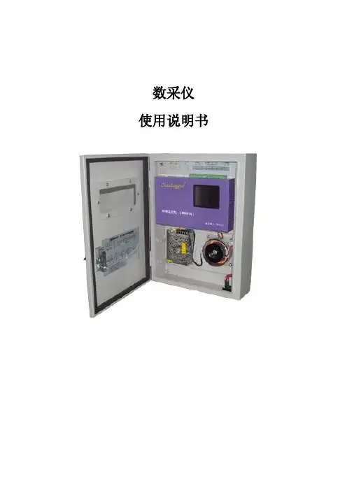
数采仪使用说明书目录1 前言........................................................................................................................................... 31.1 概述.................................................................................................................................... 31.2 功能特点............................................................................................................................ 31.3 技术指标............................................................................................................................ 42 安装和接线说明....................................................................................................................... 52.1 接线图................................................................................................................................ 52.2 指示灯状态........................................................................................................................ 63 数据采集仪设置....................................................................................................................... 73.1 用设置软件设置................................................................................................................ 73.1.1 设置前准备................................................................................................................. 73.1.2 修改常规参数............................................................................................................. 73.1.3 模拟量通道设置......................................................................................................... 83.1.4 串口协议和网口的设置............................................................................................. 93.1.5 关于串口污染物设置......................................................................................... 103.2 用显示屏设置................................................................................................................ 113.2.1 系统查看................................................................................................................... 123.2.2 系统设置................................................................................................................... 123.2.3 触摸屏操作............................................................................................................... 164 数采仪测试说明................................................................................................................. 204.1 本地测试........................................................................................................................ 204.1.1 测试前准备............................................................................................................. 204.1.2 测试功能................................................................................................................. 225 行业应用............................................................................................................................. 235.1 典型应用........................................................................................................................ 236 升级程序............................................................................................................................. 246.1 升级操作..................................................................................................................... 246.2 升级注意事项............................................................................................................. 241 前言1.1 概述环保专用采集仪是我公司为满足环保行业特殊需求定制开发的一款高性能数据采集传输设备。
G01通用数据采集仪和分析系统使用说明书中国地震局工程力学研究所目录一.功能和用途说明--------------------------------------------------------------3 二.软件安装步骤说明----------------------------------------------------------3 三.软件使用说明-----------------------------------------------------------------4 四.采集仪使用说明------------------------------------------------------------24一、功能和用途说明本系统包括采集仪和软件两个部分。
采集仪为16位、USB总线、最高采样率可达到400KHz的16通道的数据采集仪器。
软件有数据采集、数据触发采集、时域滤波、波形编辑、数据微分、积分和统计、频域分析、自动判断结构固有频率、结构振型分析、多通道信号失真度测量、虚拟电压表和示波器共11个模块组成。
提供了多种采集方式、丰富的数据时域分析、频率分析等功能。
可用于地脉动、结构脉动、爆破、桥梁、大坝和结构等建筑物的健康诊断和分析、环境振动影响分析、结构振型分析等。
二、安装步骤1. 先安装驱动程序。
解压缩“数据采集驱动程序”文件,解压缩后选择“USB2080”文件里面的“app”文件,打开“app”文件,点击setup。
如果已经安装了波速测量软件、挠度测量软件、振动台标定软件中的任何一个驱动程序,在这不需要再安装驱动程序,直接安装应用程序。
2.安装应用软件。
打开”数据采集应用软件”文件,点击setup。
安装完后。
3.安装完后,连接好仪器和电脑,电脑会自动安装仪器的USB口驱动,按照提示分别选择“自动安装”、“只安装一次”,此过程需要一定的时间,请耐心等待。
4.到电脑的“所有程序”里就可以看到了“中国地震局工程力学研究所数据采集软件”了。
广州致远电子股份有限公司DM100数据采集记录仪修订历史目录1.前言 (1)1.1关于本说明书 (1)1.2安全须知 (1)2.基本操作 (2)2.1操作流程 (2)2.2安装模块 (2)2.3连接单元 (3)2.4输入输出接线 (3)2.4.1模拟输入模块DM90XA接线 (3)2.4.2数字模块接线 (4)2.5打开电源 (4)2.6配置系统 (5)2.6.1设置IP地址 (5)2.6.2设置时间日期 (6)2.6.3板卡自动配置 (6)2.7设置参数 (7)2.7.1设置测量输入 (7)2.7.2设置报警条件 (8)2.7.3设置测量周期 (9)2.7.4设置记录条件 (9)2.7.5设置显示组 (11)2.8测量/记录 (12)2.8.1查看测量结果 (12)2.8.2开始/停止记录 (12)2.8.3浏览历史记录 (12)3. Modbus通信操作 (15)3.1Modbus服务器 (15)3.1.1接线 (15)3.1.2设置Modbus服务器功能 (15)3.1.3客户端设备读写DM100/DP100的数据 (16)3.2Modbus客户端 (18)3.2.1接线 (18)3.2.2设置Modbus客户端 (19)3.2.3查看Modbus通信结果 (22)1.前言1.1 关于本说明书本说明书说明数据采集记录仪DM100/DP100的安装、接线方法,和基础操作。
本说明书对应以下型号的产品。
1.2 安全须知●在使用测试仪及其配件之前,请先完整阅读使用说明书;●请勿在高温、有爆炸性气体、蒸汽或者有大量灰尘的地方使用记录仪;●运输和保存本产品时,请确保记录仪处于关机状态;●如需测试本产品,请使用合格的测试设备或检测装置;●记录仪如果出现问题需要维修,请勿自行拆卸,请及时与本公司联系。
2.基本操作本产品的使用说明书可以从以下地址下载阅览。
URL:最新版固件可以从以下地址下载安装。
URL:2.1 操作流程2.2 安装模块一台主机DM100(或扩展模块)最多可以连接10个采集模块。

MDR-8.07 移动数据记录器操作使用说明书北京京南航天数据技术有限公司目录1简介 (4)1.1用途 (4)1.2主要特点 (4)1.3 主要技术指标 (4)1.4设备组成 (4)1.4.1电源适配器 (5)1.4.2 MDR采集器 (5)2MDR软件安装 (7)2.1 硬件驱动安装 (7)2.2 MDR控制软件安装 (8)2.2.1软件安装条件 (8)2.2.2软件安装 (8)3MDR列表配置 (12)4MDR系统连接 (15)4.1 USB连接 (16)4.2网络连接 (16)4.3串口(RS422)连接 (17)5控制软件主界面 (17)5.1 菜单项 (19)5.1.1 系统配置 (19)5.1.2 数据操作 (19)5.1.3 数据显示 (21)5.1.4 应变调整 (21)5.1.5 标定 (22)5.1.6 其他菜单 (22)5.2 工具栏 (23)5.3 控制面板 (23)5.4 显示窗口 (24)6参数设置 (25)6.1 参数设置界面 (26)6.2 统一参数 (28)6.3 滑动平均 (28)6.4 触发类型设定 (29)7数据传输 (29)7.1 通道选择 (32)7.2 数据传输 (32)7.3 图形显示开关和显示图形延时 (32)7.4 图形操作 (33)8传感器标定 (33)9MDR数据采集步骤 (36)9.1 MDR连接 (36)9.2 MDR列表配置 (36)9.3 参数设置 (38)9.4 数据实时显示 (38)9.5 数据采集 (39)9.6 数据传输 (40)1简介1.1用途移动数据记录器 (Moving Data Recorder) 简称MDR,是北京京南航天数据技术有限公司自主研制具有国际领先水平的高技术产品;能够记录冲击、噪声、振动、速度、位移、过载、应变、陀螺、温度、压力、数字等多种信号,适用于恶劣环境下的动态、静态数据采集记录;广泛应用于桥梁、铁路、风能、教学、煤炭机械、特种设备、汽车碰撞、运输实验、分离实验、爆炸试验、摩拖车颠簸、飞行试验中的系统测量和设备检测等领域。
数据采集仪使用说明书一、引言数据采集仪是一种用于收集、存储和分析数据的设备,广泛应用于各个行业的数据采集工作。
本使用说明书将详细介绍数据采集仪的使用方法和注意事项,以确保用户正确、有效地操作设备,提高数据采集的准确性和效率。
二、产品概述1. 产品外观及配件数据采集仪外观美观,整体设计简洁大方。
标配配件包括数据采集仪主机、电源适配器、USB数据线、使用说明书。
2. 技术参数为了更好地了解产品的功能和性能,以下是数据采集仪的一些主要技术参数:- 采集通道数:8个- 采集精度:16位- 采样频率:最高1000Hz- 存储容量:最大支持64GB的SD卡- 数据传输接口:USB、Wi-Fi、蓝牙三、使用方法1. 准备工作在开始使用数据采集仪之前,请确保已经完成以下准备工作:- 将数据采集仪主机连接到电源,并确保电源正常;- 插入SD卡,确保存储容量充足;- 通过USB数据线将数据采集仪与电脑连接。
2. 采集设置- 打开数据采集仪主机,进入菜单界面;- 使用上下方向键选择“采集设置”选项,并按确认键进入;- 针对不同的采集需求,设置采样频率、采集通道数等参数;- 根据需要选择数据采集的时间段或触发条件。
如需设置触发条件,请选择“触发设置”选项。
3. 数据采集- 设置完毕后,按下开始采集按钮,数据采集仪将开始工作;- 在采集过程中,请确保设备平稳放置,避免产生干扰;- 采集完成后,保存数据并关机。
4. 数据导出和分析- 断开数据采集仪与电脑的连接,将SD卡插入读卡器;- 此时,可以使用电脑上的数据处理软件进行数据导出和分析;- 使用分析软件,打开数据文件,进行数据处理、绘图等操作。
四、注意事项1. 使用环境数据采集仪适用于室内和室外环境,但请注意避免潮湿、高温、高压、腐蚀性气体等可能对设备造成损害的环境。
2. 使用方法- 请按照本说明书的步骤正确操作数据采集仪,避免因错误操作导致设备故障或数据丢失;- 在操作过程中,请勿拆卸数据采集仪主机或随意改动设备内部元件;- 避免让数据采集仪与尖锐物品直接接触,以防刮伤设备表面。
Operation Manual of USB Data Logger(Version: 1.31)1. Introduction: (3)1.1 Features: (3)1.2 USB temperature data logger: (3)1.3 LCD symbols display instructions: (4)1.4 USB temperature humidity data logger: (4)1.5 LCD symbols display instructions: (5)1.6 Button instructions: (5)1.7 Install battery: (5)1.8 Install USB data logger: (6)2 Quick Start (7)3 Connecting the Logger to PC (7)4. Setting Up the Logger to Record Data (8)5. Download data from the logger (10)6. Delete all the logs from the logger (11)7. Data Listing Window (11)8. Exporting Logger Data (12)9. File List (13)1.Introduction:HE170 USB series has USB interface, enjoying elegant appearance and compact construction, specially designed for refrigerator and cold-chain transportation as well as container transport applications. HE170 USB series adopts friendly USB interface, friendly mounting bracket and the screws. HE170 USB series can show temperature/temperature and humidity simultaneously as well as the battery indication. The OK key can help to check the Max/Min/Current value and the upper and lower limits.1.1Features:l Waterproof and dustproof standard IP67, resisting moisture, dew-point temperature and dust.l Temperature and humidity limit can be set. LED lights when the setting value being exceeded.l Ultra-lower consumption design, 1/2AA 3.6V Li battery, working for 12 months and easy to install your battery.l Transfer logging data to PC through software and can be saved as different types to ensure the existence.l Adopt high sensitive sensor, enjoy fast response and high accuracy.1.2USB temperature data logger:8①LCD display②Button③LED warming light when the temperature value exceeds the setting limits.④USB connection port.⑤Waterproof ring.⑥Battery replacement position.⑦Waterproof transparent cover.⑧Fixed bracket.1.3LCD symbols display instructions:①HI symbol display shows being the temperature upper limit setting status.②LO symbol display shows being the temperature lower limit setting status.③Battery power indication.④MIN symbol display shows being the minimum temperature value checkingstatus.⑤MAX symbol display shows being the maximum temperature value checkingstatus.⑥LOG symbol display shows being the logging status.⑦(Celsius and Fahrenheit)⑧Temperature value symbol display.1.4USB temperature humidity data logger:8①LCD display.②Button.③LED warming light when the temperature and humidity values exceed thesetting limits.④USB connection port.⑤Waterproof ring.⑥Battery replacement position.⑦Waterproof transparent cover.⑧Fixed bracket.1.5LCD symbols display instructions:①HI symbol display shows being the temperature and humidity upper limitssetting status.②LO symbol display shows being the temperature and humidity lower limitssetting status.③MAX symbol display shows being the maximum temperature and humidity valueschecking status.④MIN symbol display shows being the minimum temperature and humidity valueschecking status.⑤Battery power indication.⑥Units symbol display:(Celsius and Fahrenheit)humidity unit⑦Temperature and humidity values symbol display.1.6Button instructions:1.6.1:Press this button for long to 5seconds can turn on/off thecancheck the MAX, MIN, High and low warming limits values as well as the current value under the working status.1.7Install battery:1.7.1Firstly, use your tool ① to open the battery back cover ②, then installyour battery ③.1.8 Install USB data logger:1.8.1 Use screw ② to fix the bracket ① onto the wall and then install the datalogger as follows:2Quick StartFollow the procedure below to quickly start using your data logger:1. Connect the data logger to a free USB port on the computer.2. Start T oAnalyzer U software on the PC.3. From the toolbar select Connect.4. Then you can setup or download data, delete data from the logger.5. Unplug the cable from the logger, and then the logger is in stop mode.6. Press OK for about five seconds, the logger will be power on (LOG mode) or off (OFFmode).Note: The logger has three modes:1. LOG: In the mode, the logger samples and records data timely.2. OFF: In this mode, the logger stops to sample and record, and the LCD display is off. 3Connecting the Logger to PCT o connect the logger to the computer, follow these steps:1. Connect the USB cable to the logger and to a free USB port on the computer.2. If you are connecting the logger to the PC for the first time, the logger willautomatically be recognized and installed on the computer.3. Start T oAnalyzer U analysis software.4. Click the icon4.S etting Up the Logger to Record DataT o set the logger to start recording data, click thel: Synchronize the PC time to the logger.l Name: Gives a name to the logger.l Type: The device type.l Model: The device model.l Serial No: Every logger has a SN with 10 characters. The length must be 10.l LOG Intervals(s): The interval of recording.l Log Count: The count of the logs that the logger has recorded.l Memory capacity: The total capacity of the logger memory. One reading includes time and three channels’ data.l T emperature Unit: The selection of C and F.l Start Mode: There are three start modes: No Delay / Delay / Timer.No Delay: The logger will start to log immediately.Delay: The logger will start to log after a delay time.Timer: The will start to log at a specific time.Note: If the logger is OFF, the logger cannot record any logs.Calibrate the logger: The logger is factory calibrated to an accuracy given in the device specifications. However, there may be times when you wish to adjust the calibration of your logger. T oAnalyzer provides you with the ability to perform a single point offset calibration. This calibration can be used to increase the accuracy of the logger for a restricted data range.l CH1 offset: The offset of channel one.l CH2 offset: The offset of channel two. (If the logger is temperature logger, the CH2 and CH3 are useless.)l CH3 offset: The offset of Dew Point.5.D ownload data from the logger.T o get the recorded logs from the logger, connect the logger to your computer and clickthe6.D elete all the logs from the logger.T o erase all data from the logger, connect to the logger, and then clickbutton on the toolbar, and then the data listing window is shown below.The data pane lists the data samples collected by the logging device.The column width of each column is adjustable by using the left mouse button and dragging the column the desired width.8.E xporting Logger DataY ou can use ToAnalyzer to export sample data to a text file or to a Microsoft Excel file or BMP file.ll。

JY-I智能数据采集仪系统V1.0用户手册JY-I智能数据采集仪系统V1.0 - 1 -1、概述根据国内表盘式试验机的特点,结合检测单位检测信息管理计算机化的需求,在调查国内数十家检测单位的十几种表盘式显示试验机的实际使用状况,听取多名业内专家及实际操作员的意见基础上,经多年的研发,并在现场的使用过程中逐步积累经验和发现问题不断改进,现推出现场无需电脑采集国内首创的新产品“PKPM建材试验机智能数据采集仪”。
仪器具有以下特点:●仪器自带液晶数显,可显示实时采集曲线图、样品编号、采集力值、准确度高,采集数据与表盘读数完全一致(改造后试验机精度达到一级)。
现场无需电脑,采集的数据自动传送到管理系统的数据库服务器,采集的数据有最大力值、实时采集曲线图数据,对钢筋机还自动算出屈服强度,显示并传到服务器。
●仪器使用220V的交流,产品本身内部设有滤波模块,能抑制一定幅度的外部电源的浮动,保证仪器核心部分的正常工作,对等位电网内的大型电机起降、变频器工作干扰、电机调速器工作所产生的脉冲和浪涌有一定的扼制作用,能在比较恶劣的电气环境、温度和湿度环境内出色工作。
●采用2线制现场总线的工业成套系统应用解决方案,与检测信息系统软件自动联机,电脑收样后的样品编号信息自动发送到数据采集仪,无需手工输入样品编号;采集仪完成每组试件的试验后,采集仪可根据试验员的主动判断后决定是否对试验结果作出自动上传和软件处理,或者舍弃然后换试件重做,试验员无须手工记录试验数据,从而可以实现从试验到出报告阶段试验数据的无缝传输,大大降低了试验员和报告审核工作的繁复程度和劳动强度,减少了发生错误的几率。
●实验室的各个科室,各种项目实验的不同厂家、不同类型的试验机,都可以通过此智能数据采集仪对试验信息,试验数据进行集中管理和控制。
典型的模型就是:依托一台配置有COM通讯口的PC机,通过COM口连接一个RS232 转RS485的转换器,下驳最多可12台智能数据采集仪,实现对只能采集仪对各试验机的试验数据的集中采集。

JY-I智能数据采集仪系统V1.0用户手册一、概述根据国内表盘式试验机的特点,结合检测单位检测信息管理计算机化的需求,在调查国内数十家检测单位的十几种表盘式显示试验机的实际使用状况,听取多名业内专家及实际操作员的意见基础上,经多年的研发,并在现场的使用过程中逐步积累经验和发现问题不断改进,现推出现场无需电脑采集国内首创的新产品“PKPM建材试验机智能数据采集仪”。
仪器具有以下特点:●仪器自带液晶数显,可显示实时采集曲线图、样品编号、采集力值、准确度高,采集数据与表盘读数完全一致(改造后试验机精度达到一级)。
现场无需电脑,采集的数据自动传送到管理系统的数据库服务器,采集的数据有最大力值、实时采集曲线图数据,对钢筋机还自动算出屈服强度,显示并传到服务器。
●仪器使用220V的交流,产品本身内部设有滤波模块,能抑制一定幅度的外部电源的浮动,保证仪器核心部分的正常工作,对等位电网内的大型电机起降、变频器工作干扰、电机调速器工作所产生的脉冲和浪涌有一定的扼制作用,能在比较恶劣的电气环境、温度和湿度环境内出色工作。
●采用2线制现场总线的工业成套系统应用解决方案,与检测信息系统软件自动联机,电脑收样后的样品编号信息自动发送到数据采集仪,无需手工输入样品编号;采集仪完成每组试件的试验后,采集仪可根据试验员的主动判断后决定是否对试验结果作出自动上传和软件处理,或者舍弃然后换试件重做,试验员无须手工记录试验数据,从而可以实现从试验到出报告阶段试验数据的无缝传输,大大降低了试验员和报告审核工作的繁复程度和劳动强度,减少了发生错误的几率。
●实验室的各个科室,各种项目实验的不同厂家、不同类型的试验机,都可以通过此智能数据采集仪对试验信息,试验数据进行集中管理和控制。
典型的模型就是:依托一台配置有COM通讯口的PC机,通过COM口连接一个RS232 转RS485的转换器,下驳最多可12台智能数据采集仪,实现对只能采集仪对各试验机的试验数据的集中采集。
DS201 User’s ManualContentsI Product Intro (2)II General Safety Rules (2)III Major Functions (2)IV Operation Precautions (3)V General Inspection (3)VI Functional Inspections (3)VII Battery Recharging Instruction (3)VIII SD Card Storage Instruction (3)IX Firm ware Upgrades (3)X Product Familiarization (5)1. Interface and Buttons (5)2. Screen (5)XI Measurement Operation Instruction (6)1. Parameter Area Intro (6)2. Measurement Area Intro (6)3. Specific Parameters Intro (6)Hidden two waveform operation line (10)Zero voltage calibration (13)XII Application Examples (15)1. Example One: Measure Simple Signal (15)2. Example Two: Measure with Cursor (16)3. Example Three: Save Waveform Image (17)4. Example Four: Acquire Single Signal (18)5. Example Five: C ompare Waveform Signals (18)I Product IntroDS201 pocket size oscilloscope is a compatible 32bit digital storage oscilloscope. Based onARM-M3, it’s equipped with 320*240 color display, SD card, USB port and recharging function. It’s compact, simple to operate; meets the basic demands of school lab, electric furniture repairmen and electric engineering.II General Safety RulesTo ensure your safety & avoid any damages to the product/connected devices, please read the following safety rules carefully. To avoid any possible dangers, please use this product according to the rules.Use appropriate power cord. Please use dedicated power cord which is certified in the country/region.Connect/disconnect properly. Do not plug/unplug when the probe(s)/test lead(s) is connected to the power source. Before you plug/unplug the current probes, please disconnect the power to the circuit-under-test.Observe all terminal ratings. To avoid fire/electric shock, please don’t measure signal with DC100V or above, or the device might be destroyed. Please read the manual carefully to know the detailed info of related ratings before connection.Please do not operate in humid environment.Please do not operate in inflammable/explosive environment.Please keep the surface of the product clean and dry.III Major FunctionsIV Operation Precautions▌Temperature:Working condition:+0℃to +500℃Non-working condition:-20℃to +60℃:▌Humidity:Working condition:High temperature:40°C - 50°C,0%-60%RHWorking condition:Low temperature:0°C - 40°C,10%-90%RHNon-working condition:High temperature:40°C- 60°C,5%-60%RHNon-working condition:Low temperature:0°C - 40°C,5%-90%RHV General InspectionWhen you get a new DS201, it’s suggested to inspect the product by the following steps:1.Inspect for damage caused by shipping.If the carton/plastic protection pad is seriously damaged, please keep the package until the product and accessories pass the inspection electrically and mechanically.2.Inspect the productPlease contact the company if the following problems occur: 1) product surface is damaged, 2) product doesn’t work properly, 3) product does not pass performance test.If the damage is resulted from shipping, please keep the package and contact the transportation department/ RIGOL distributor who is in charge of this service, for repair or exchange.VI Functional InspectionMake a quick functional inspection to ensure the product is working soundly. Please perform following steps: 1.Turn on the power supply, access homepage of the oscilloscope.2.Connect the oscilloscope with standard signals (e.g. square wave 20KHz,Vpp=5V), set the switch on probe tip as 1X, plug oscilloscope probe to the jack.Check whether the measured signal value is the same as the standard value; it can be calibrated if the margin is small.VII Battery Recharging InstructionWhen the battery sign shows as “”, or when the display is dim, please recharge in time. The product can be power on or off while recharging.VIII SD Card Storage InstructionInsert SD card into the slot before using SD card to store waveform images. This product supports SD Card storage. (Max. memory: 2G)IX Firmware UpgradeTo upgrade firmware, please perform following steps:1. Open web to access , download the latest applicable firmware to your PC.2. Simultaneously press “—” of DS201 and turn on power supply, enter DFU firmware upgrade mode.3. Use USB to connect DS201 to your PC, a removable disk named DFU V3_11_A will appear on your PC.Copy the hex firmware to the root directory of your disk. After the extension of the firmware changes from “hex” to “rdy”, restart DS201, thus firmware is upgraded.X Product Familiarization1. Interface & Buttons2. ScreenThe screen display is depicted as below:NOTE:There are corresponding colors for items in Parameter Area and Measurement Area.XI Measurement Operation Instruction1.Parameter Area Intro/2.Measurement Area Intro3.Choose the items in parameter area through “+” or “_”. Pres s “M” to access parameter setting menu, use “+” and “_” to choose the parameter item, and then use “| ” and “ |” to change the parameter value of the place where the cursor blinks.(1)Annotation of Yn parameters(2)Annotations of Xn Parameters(3)Annotations of Tr parameters(4)Annotations of Me Parameters(5)Annotations of Ex ParametersSet the cursor to the "EX" option, press the "M" pop-up window, select "Ext Refn" option, then Through "| " or " |" change cursor blink parameter values for the "Off", the two waveform operation line (purple line)Be hidden, as shown in the figure below.(7)Annotations of Sn ParametersOscilloscope Calibration:Press ||Zero voltage calibration: as the chart, "1.0 V" gear, zero line is inaccurate and head for the "PO - 17", needs to be calibrated.The calibration Steps:1. Through "+" or "-"button to move the cursor option" Ca "option, press"M "pop-up" Calibration"Window.2.Press " ||" button to enter the calibration options window.3.Select "Cal Zero" option, by | or" | "change the cursor blink in the parameter value is adjusted for" PO 0.0 " Zero calibration line, line with the arrow to a level.4.The calibration after the zero line, we need to save the Settings after calibration. By "+" or"-” button tomove the cursor option "Yn" option, long press " ||" button, the pop-up."Save ParamTab?"Window, press the " ||" button to save the calibration.5.The other gear have zero line position error, the calibration in accordance with theabove method.XII Application Examples1.Example One: Measure Simple SignalObserve one unknown signal in a circuit, quickly measure & display the signal’s frequency & peak-to-peak value. Please operate according to following steps:Connect the channel probe to the detection point of the circuit.Set the Channel mode as AUTO, adjust the (Horizontal) time calibration and (Vertical) voltage calibration, make sure the signal displays clearly.Adjust Threshol horizontal triggering position to make signal display stable.Use “+”or “-” to choose Me items in Measurement Area,then press “M”, use “| ”or “ |” to choose the signal parameters that need analysis, e.g. Freq(frequency), Duty(dutyfactor), Vpp(peak-to-peak voltage)etc., the measured value will be displayed at the lower right corner of the screen, as shown in the image below:2.Example Two:Measure with CursorA cursor can be used to measure the time and voltage of the waveform very quickly. (1)Measure the cycle of signal sourcePlease operate according to the following steps:Use “+” or “-” to choose Yn items in Measurement Area.Press “M”Use “| ” or “ |” to choose CursorV1Use “+” or “_” to adjust the position of CursorV1 to the crest.Use “| ” or “ |” to choose CursorV2Use “+” or “_” to adjust the position of CursorV2 to the valley.And get:△V=1.00mS i.e. the cycle of signal source. As shown in the image below:(2)Please operate according to following steps:Use “+” or “_” to choose Yn items in Measurement AreaPress “M”Use “| ” or “ |” to choose CursorV1Use “+” or “_” to adjust the position of CursorV1 to the crestUse “| ” or “ |” to choose CursorV2Use “+” or “_” to adjust the position of CursorV2 to the valleyAnd get:△V=2.08V. i.e. the cycle of signal source, as shown in the image below:3. Example Three :Save waveform imageSometimes waveform images need to be archived or analyzed on PC platform. Please operate according to following steps:Use “+” or “_” to choose the Fn items in Measurement Area, press “M ”, use “| ” or “ |”to choose Save Bmp, and then use “| ”or “ |” to choose the file name on the lower right corner of the screen ,e.g.Save000.BMP ,as shown in the image; and then press “ ||” to save it to the built -in U disk.Just copy the image to your PC, and you can analyze the waveform image.4.Example Four: Acquire Single SignalIt’s the superiority and feature of digi tal oscilloscope to easily aquire non-periodic signals like impulsion and sentus. To aquire a single signal, you need a priori knowledge of it to set trigger level & trigger edge. E.g. if impulsion is a TTL PWL logic signal, trig level should be set as 2V, trig edge as rising edge trig. If the signal is not stable, it’s suggested to observe in a normal triggering mode to define trig level & trig edge.Operation steps are as follows:Connect the channel probe to the detection point of the circuit.(rising edge trigger)Triggering setting: DC Coupling.Adjust proper triggering PWL.Use “+”or “_”to choose Tr items in Measurement Area, press “M”; use “| ”or “ |”to choose Syncmode,and then use “| ”or “ |”to choose single touch mode, wait for the signal that match the triggering condition to show up. If there is one signal reaching the preset PWL, it will be sampled and displayed on the screen. As shown in the picture.5. Example Five: Compare waveform signalsPlease operate according to following steps:Input standard signal waveform to the channel, chose Data in EX, and then choose Save Dat 01 to save the waveform, as shown in the image below.Input unknown to-be-measured signal to the channel, choose Load Dat01→EX→Data, and then the to-be-compared waveforms are shown on the screen simultaneously, as shown in the image.。
ANC-Micro-XX自动化数据采集仪使用说明手册目录1.产品概述 (3)1.1.产品简介 (3)1.2.工作原理 (4)1.3.主要技术参数 (4)2.系统组成 (5)2.1.结构设计 (5)2.2.测量模块 (6)2.3.电源模块 (7)2.4.无线通讯模块 (9)2.4.1.工作原理 (10)2.4.2.产品规格 (11)2.4.3.使用说明 (12)2.4.4.指示灯说明 (14)2.5.加热除湿模块 (15)2.5.1.产品特点 (15)2.5.2.产品规格 (16)2.5.3.使用注意 (16)3.传感器接入 (17)3.1.仪器绝缘要求 (17)3.2.电缆接头处理 (17)4.关于通讯连接 (20)4.1.与上位机的通讯连接 (20)4.2.组网通讯 (21)4.3.电源防雷与接地 (22)5.关于系统软件 (24)6.安装说明 (25)7.使用与维护 (26)7.1.使用注意事项 (26)7.2.现场问题应急处理方法 (26)8.单元及附件配置 (28)1.产品概述1.1.产品简介ANC-Micro-XX系列自动化数据采集仪,是用于工程安全自动化测量的新一代多通道高精度的数据采集仪,自动化数据采集仪具有32位高性能浮点处理器、全金属外壳设计,适用于长期监测中各种振弦式传感器输出的频率信号计算及温度采集、以及对RS485输出方式的传感器进行测量及记录,设备操作简单。
本数据采集系统集成化程度高、抗干扰性能强,采用通用标准RS485接口及接口防雷保护等设计使采集仪可在环境恶劣的安全监测工程中安全稳定地运行。
由ANC-Micro-XX系列自动化数据采集仪组成的分布式网络测量系统广泛应用于水电站、公路、桥梁、边坡、地铁等多种场合中变形、应力、应变、渗压等自动化监测。
(1)产品特点:高强度铝合金外壳,防护能力强实现远程升级功能离线采集功能全自动调零,减少人工操作多通道电子半导体开关切换,无机械继电器,使用寿命长,适合长期监测通信接口采用10KA防雷设计,户外使用可靠性高(2)功能特点:ANC-Micro-XX系列自动化数据采集仪具备兼容、智能等特点,具体如下:兼容:可接入多种类型的传感器,单台采集仪最大接入能力达到40支传感器,具备强大的组网通讯能力,标配RS485、LAN、4G、WIFI多种通讯方式,可扩展北斗短报文通讯;智能:设备具有多种工作模式(实时测量模式、正常工作模式);可配置传感器计算公式及阈值。
G01通用数据采集仪和分析系统使用说明书中国地震局工程力学研究所目录一.功能和用途说明--------------------------------------------------------------3二.软件安装步骤说明----------------------------------------------------------3三.软件使用说明-----------------------------------------------------------------4四.采集仪使用说明------------------------------------------------------------24一、功能和用途说明本系统包括采集仪和软件两个部分。
采集仪为16位、USB总线、最高采样率可达到400KHz的16通道的数据采集仪器。
软件有数据采集、数据触发采集、时域滤波、波形编辑、数据微分、积分和统计、频域分析、自动判断结构固有频率、结构振型分析、多通道信号失真度测量、虚拟电压表和示波器共11个模块组成。
提供了多种采集方式、丰富的数据时域分析、频率分析等功能。
可用于地脉动、结构脉动、爆破、桥梁、大坝和结构等建筑物的健康诊断和分析、环境振动影响分析、结构振型分析等。
二、安装步骤1.先安装驱动程序。
解压缩“数据采集驱动程序”文件,解压缩后选择“USB2080”文件里面的“app”文件,打开“app”文件,点击setup。
如果已经安装了波速测量软件、挠度测量软件、振动台标定软件中的任何一个驱动程序,在这不需要再安装驱动程序,直接安装应用程序。
2.安装应用软件。
打开”数据采集应用软件”文件,点击setup。
安装完后。
3.安装完后,连接好仪器和电脑,电脑会自动安装仪器的USB口驱动,按照提示分别选择“自动安装”、“只安装一次”,此过程需要一定的时间,请耐心等待。
4.到电脑的“所有程序”里就可以看到了“中国地震局工程力学研究所数据采集软件”了。
1 介绍2. 安装3. 启动与启动屏幕4. 校验5. 测量6. 开始测试6.1 压差(Pdiff )的调节6.2 开始测试6.2.1 简介6.2.2 测试7. 历史和数据收集8. 参数化法8.1 “SETTINGS置”模式8.2 “CALIBRATION校准”模式8.3 旁压仪斜度的校准9. 使用建议9.1 校平9.2 电源供应9.3 体积10 GeoBOX及其打印机的使用10.1 GeoBOX10.2打印机10.3 GeoBOX和打印机保养10.3.1更换打印纸&无线连接10.3.2更换GeoBOX的电池你刚刚获得到的是最新的由APAGE 和GEOMATECH 发的压力测量数据记录仪。
它与APAGE 和 GEOMATECH 力机相兼容,配备 GeoSPAD 性能并与 APAGE 全能 中央单元GEOBO 有联系。
该设备用于调控整个压力测量实验步骤,并且自动记录这个实验的数据和结果。
它是一个现场单元,防水(IP65),结实可靠,是最新技术研发的成果:小型移 动电脑,遥控热敏打印机,USB 盘里的实验记录,或者传输GPRSi GeoVISION,大 内存以保证实验数据的可靠记录,提供多语言(法语,英语,德语,西班牙语, 葡萄牙语和意大利语)。
虽然这些压力计保持着它们产地的规格,尤其是在没有使用 GEOBO 的情况下的 手动运用,然而 GeoSPAD 可以改造成为 Menard, APAGEO, GEOMATE 型的压力 计。
甚至在检查以后可以改造成为其他商用压力计。
装在密封盒里的数据获取设备,通过 WIFI 与GeoBOXS 行通迅。
两个0--100Bar 的压力传感器,结实且准确 度高,与数据获取设备,压力表的水和空气 线路相连接。
一个超声波体积传感器,或一个配有浮子的 磁致伸缩传感器。
技术的选择应以单元的使 用情况而决定。
磁致伸缩传感器推荐在近海 区域作业使用。
一个设备电源插头,在压力表和它电源线与 弹簧夹的默认情况下。
LM-02智能数据采集仪使用说明书概述LM型智能测力仪,主要适用于各种测力装置的力值测量和显示。
本系列智能测力仪能够把测得得力值数据由单片机根据使用要求进行处理。
智能测力仪,能适用十多种场合,用途广泛。
一、主要技术参数额定工作电压:~220V(±10%)功耗:≤50VA非线性重复性误差:≤±1%分辨能力:工作温度:0~40℃外形尺寸:270×90×280(宽×高×深)仪表保险丝:0.5A功能压力显示:10位数码显示1.5位随机显示2.5位峰值保持显示加荷速度显示:KN/S(千牛顿/秒)二、安装及接线1、将本仪器装置于适当位置即可,电源、传感器、过载输出接口分别对应本仪器后盖上的插口接线,见附图(1)2、本仪器面板分布见附图(2)三、使用方法(1)通电:接通电源显示数为无意义数。
(2)清零按“清零”键,显示器显显示0.0,如果不是0.0可重复按“清零”键,(如出现小于2.0的数也属于正常,可进行以下操作。
(3)检测,在过程(2)后加荷,“LOAD和SPPED”显示窗显示值为随机显示,力值随加荷大小显示,如需观察加载速度,可按“∆”键,显示窗即显示加荷速度,单位为KN/S(千牛顿/秒),再按“∆”键可恢复显示力值,“PEAK”显示窗显示为峰值显示。
(4)设定报警值,按“功能”键后,显示窗显示“C1”后,按“▲”后显示窗显示数值,两用“∆”修改数值,用“▲”移位,输入完毕后按确认键退出。
四、标定按计量法规定,本测力仪一年标定一次,且有当地技监局指定的法定计量部门进行。
注意:用户请勿进入标定状态,否则把出厂时标定的标准数据失掉后,本仪表将不能正常工作。
2、动忐力值及加载速度显示窗仪器通电三分钟后入随机状态下用三等标准测力计进行,步骤如下:(1)加荷值额定值三次后卸载。
2)按“清零”键,使显示器显示为0.03)平稳加载,开始标定,从额定载荷的20%开始标定标定应不少于五点,五点应为最大负载的20%、40%、60%、80%、100%相适应,重复分级加荷三次,并记录每级的现实数,其误差应在1%以内。