数据采集软件使用说明书
- 格式:doc
- 大小:241.50 KB
- 文档页数:3

用户说明书(数据采集)UsermanulofDatacollection文档历史目录1系统说明.............................. 错误!未指定书签。
1.1PilotPioneer简介................ 错误!未指定书签。
1.2操作系统........................ 错误!未指定书签。
1.3最低配置........................ 错误!未指定书签。
1.4建议配置........................ 错误!未指定书签。
2软件主界面............................ 错误!未指定书签。
2.1导航栏.......................... 错误!未指定书签。
2.2菜单栏.......................... 错误!未指定书签。
2.2.1【File】菜单................. 错误!未指定书签。
2.2.2【View】菜单................. 错误!未指定书签。
2.2.3【Configuration】菜单........ 错误!未指定书签。
2.2.4【Record】菜单............... 错误!未指定书签。
2.2.5【Replay】菜单............... 错误!未指定书签。
2.2.6【Workspace】菜单............ 错误!未指定书签。
2.2.7【Interface】菜单............ 错误!未指定书签。
2.2.8【Tools】菜单................ 错误!未指定书签。
2.2.9【Report】菜单............... 错误!未指定书签。
【Analysis】菜单............. 错误!未指定书签。
【Windows】菜单.............. 错误!未指定书签。

SensorHub多通道数据采集器用户手册版本:V3.0目录1.产品介绍 (5)2.设备快速使用流程 (7)设备连接SenseCAP云平台 (7)设备连接第三方的传感器和服务器 (8)3.组装设备 (9)设备包装清单(SensorHub) (9)设备接口介绍 (10)安装SIM卡 (10)安装天线 (11)连接传感器 (12)连接电源线 (12)4.配置设备连接到SenseCAP云平台 (13)绑定设备 (13)4.1.1注册账号 (13)4.1.2下载手机App (13)4.1.3绑定设备和传感器 (13)设备上电开机 (14)登录云平台查看数据和状态 (15)云平台使用说明 (15)API使用说明 (16)5.配置设备连接到第三方服务器 (17)准备工具 (17)5.1.1上位机配置软件 (17)5.1.2串口线连接和驱动安装 (18)配置工具功能介绍 (18)通用设置 (19)5.3.1设备编码(EUI)和上报周期修改 (21)5.3.2MQTT服务器配置 (22)5.3.3GPS配置 (24)5.3.4APN配置 (24)5.3.5读写操作和清空配置 (24)6.添加自定义传感器 (25)传感器标准及分类 (26)6.1.1用户自定义传感器 (26)6.1.2内建支持传感器 (26)用户自定义传感器示例:添加土壤温湿度传感器 (27)6.2.1准备 (27)6.2.2配置传感器基本信息 (27)6.2.3配置测量值信息 (29)6.2.4传感器测试 (31)6.2.5确认数据上传服务器 (32)在SenseCAP云平台添加自定义测量值和传感器 (36)6.3.1添加测量类型 (36)6.3.2添加传感器类型ID (37)7.故障排除和日志解析 (39)常见异常诊断 (39)7.1.1通道状态异常 (39)7.1.2在测试传感器时,报错:No sensor found. Is the sensor connected (39)7.1.3在测试传感器时,报错:[ERROR] rs485 err code: XX XX (39)日志解析 (41)8.设备安装和使用注意事项 (46)内置电池低温环境使用注意事项(必看) (46)传感器航空插头线序 (46)安装示例-数据采集器 (47)安装示例-太阳能板 (49)1.产品介绍SenseCAP是一套工业级传感网络系统,实现低功耗的环境物理量数据采集,包含可靠易用的硬件产品和软件平台服务。
®基康仪器The World leader in Vibrating Wire TechnologyBGKLogger V.4数据采集软件操作使用手册(REV.A)基康仪器(北京)有限公司地址:北京市海淀区彩和坊路8号天创科技大厦1111室电话:86-10-62698899邮编:100080 传真:86-10-62698866网址: 电子邮箱:***************.cnBGKLogger V.4数据采集软件操作使用手册(REV A)基康仪器(北京)有限公司版权所有Copyright ©2010本仪器的安装、维护、操作都要由专业技术人员进行。
基康仪器(北京)有限公司对产品有更改的权利,产品更改信息恕不另行通知。
本文件所含信息归基康仪器(北京)有限公司所有。
本文件中所有信息、数据、设计、以及所含图样都属基康仪器(北京)有限公司所有,未经基康仪器(北京)有限公司书面许可,不得以任何形式(包括影印或其他任何方式)翻印或复制、间接或直接透露给外界团体。
目录1 绪论 (1)1.1软件简介 (1)1.2版本说明 (1)2 软件安装与注册 (2)2.1安装 (2)2.2注册 (2)3 系统整体结构 (4)3.1 基础结构 (4)3.2 功能结构设计 (4)4 系统管理 (6)4.1 用户管理 (6)4.2 用户日志 (7)4.3 背景图片 (7)5 自动化配置 (9)5.1 单元配置 (9)5.2 测点配置 (10)6 自动化控制 (12)6.1 单元控制 (12)6.2 在线测量 (13)7 数据管理 (14)7.1 数据查询 (14)7.2 数据报表 (14)7.3 数据整编 (15)1 绪论1.1软件简介BGKLogger数据采集系统是由基康仪器(北京)有限公司推出的用于工程安全自动化测量的新一代产品。
本软件是整个系统中的上位机软件,能够支持基康仪器(北京)有限公司的多种自动化数据采集设备,如BGK8001低功耗数据采集仪、BGK8001系列无线数据采集仪、BGK6850A系列垂线坐标仪,BGKMicro40多通道自动化数据采集单元等。
数据采集软件使用手册第一章操作说明一、采集软件的特点(一)简便性数据采集软件是一套免安装的应用软件,在使用该软件的时候可以直接在光盘上运行,为我们的使用提供了很大方便。
同时,由于该软件不需要安装,因此不会对企业的计算机造成任何的影响。
(二)智能化无需用户提供企业所用财务软件的版本、应用数据库类型,能实现自动搜索财务软件类型、财务软件应用数据库、自动破解数据库密码(仅限服务器端)、自动搜索财务软件帐套。
附表:在服务器端或客户端及非财务软件计算机上采集的区别(三)通用性提供高级采集工具,通过数据库连接的建立,实现万能采集。
(仅限Windows系列操作系统)(四)安全性数据采集软件仅用于将企业的涉税电子数据转换成标准的电子文档,供“涉税鉴证软件”使用。
其采集的文档经过加密计算的处理,其他任何程序无法读取其数据,为企业信息的安全提供了保障。
二、代替符号的说明为了使本说明书更加简洁、明了,我们在编写本书的过程中使用了一些简单的符号代替部分图形和文字描述:第二章采集软件的操作一、采集软件运行与退出(一)采集软件的运行将涉税鉴证业务软件光盘放入到企业的装有财务软件的计算机中,双击桌面上的〖我的电脑〗,选择光盘上的〖数据转换系统〗下的“数据采集软件”并双击打开,这时系统将自动运行数据采集软件,运行的界面如下图所示:数据采集软件根据企业所使用的财务软件的性质大致分为三大类:〖国内软件〗、〖地方软件〗、〖国外软件〗和〖其它软件〗。
〖国内软件〗按软件的种类分成九小类;〖其它软件〗涵盖了铁路通信、电力等行业软件;〖国外软件〗和〖地方软件〗则根据我们所接触到的加以补充。
在使用的过程中,我们可根据企业实际采用的财务软件种类和版本加以区别选择。
(二)采集软件的退出在上面显示的运行主界面中,单击〖退出〗,即可退出数据采集软件。
二、采集软件的示范说明(一)金蝶软件金蝶软件为深圳金蝶软件科技有限公司产品,目前主要分金蝶2000财务软件、k3企业管理软件及KIS三个系列。
Mobile GIS数据采集软件用户手册北京合众思壮科技股份有限公司欢迎使用北京合众思壮科技股份有限公司开发的Mobile GIS数据采集平台软件。
Mobile GIS数据采集软件,全面支持各种GPS数据采集模式,该软件具备 GIS 点、线、面采集、地图浏览、 GIS 数据导出等常用功能,配合强大的坐标转换功能和采集数据兼容性,将成为您野外数据采集工作中的有力工具。
本用户手册中,用蓝色方框标注各窗体元素,并用蓝色字体说明。
用橙色加标号的方框表示正文中橙色字体所描述的操作动作,其标号与正文中操作标号一致。
正文中操作标号用橙色显示者表示该操作有相应的图形介绍,否则该操作仅用文字表示。
用绿色字体标示前后文中有联系的一些相关名词。
用*标记的绿色词汇在下文中会给出对应解释。
用加粗的字体表示说明的标题。
用带灰色背景的字体表示您需要注意的相关信息,这些信息通常与前后的正文紧密相关。
用红色字体表示您需要非常注意的信息,忽略这些信息,可能导致Mobile GIS工作不正常,或给出错误的数据结果。
请您在使用Mobile GIS前仔细阅读本用户手册。
在使用过程中如果有任何问题,请与北京合众思壮科技股份有限公司取得联系,我们将为您提供完善的技术服务。
1Mobile GIS主窗口Mobile GIS软件启动完成后,即显示主窗口界面。
如右图所示,主窗口界面由GIS采集、地Array图浏览功能组成,右侧有设置、工具、退出三个功能图标。
1Mobile GIS中的GIS数据采集功能是MobileGIS软件的基本和主要功能。
其中包含了点采集、线采集和面采集功能。
分别用于采集点、线、面矢量数据。
操作1:如右图(上)所示,点击“GIS采集”菜单项,弹出GIS数据采集主菜单,如右图(下)所示操作2:点击“采集点”菜单项,可进入点数据采集功能,具体操作见下文采集点部分操作3:点击“采集线”菜单项,可进入线数据采集功能,具体操作见下文采集线部分操作4:点击“采集面”菜单项,可进入面数据采集功能,具体操作见下文采集面部分23GIS 数据采集(2)——采集点Mobile GIS 提供了采集点数据的功能。

REXDC 2.0 雷磁数据采集软件操作说明书上海精密科学仪器有限公司目录一、概述二、软件的安装三、运行软件四、设置五、记录数据六、编辑数据七、输出数据八、注意事项一、概述随着计算机在分析测试中应用的日益广泛,分析测试的信息化程度越来越高。
“雷磁数据采集软件”是针对雷磁台式智能电化学系列仪器和便携式智能电化学系列仪器而编写的数据采集管理软件,可通过连接仪器和计算机的RS-232接口,实现对这两大系列的仪器测试数据的自动采集和管理。
进一步发展,可连接到LIMS 平台,以达到电化学分析测试信息化的目的。
该软件采用Microsoft Visual Basic 6 .0进行编制,具有WIN风格的操作界面,能对仪器的测试数据进行自动采集,并具有数据库存储、电子表格、曲线图、输出等数据管理功能。
二、软件的安装2.1系统要求a) CPU:奔腾或以上b) 操作系统:Windows 95或以上c) 内存:16M或以上d) 硬盘空间:10Me) 端口:空闲的RS-232接口或USB接口(需安装驱动)2.2安装方法a) 将光盘插入CD驱动器或软盘插入软驱动器。
b) 运行安装程序:REXDC2.0Setup.exe。
c) 按照安装向导的指示进行安装。
2.3USB驱动安装1、接通仪器电源,将数据线插入计算机的USB端口,打开仪器电源开关,系统提示发现新硬件,并弹出找到新硬件向导窗口,选择“从列表或指定位置安装”。
如下图,按【下一步】。
注:如果一直没有反应,换主机背后主板上的USB接口试试2、进入下图画面,选择“在搜索中包含这个位置”。
点击“浏览”在驱动软件所在位置选择Windows_2K_XP_S2K3_Vista,按【下一步】继续,系统开始自动安装驱动程序。
3、按【完成】结束安装。
4、安装完成之后,进入设备管理器,在“端口”一栏中可以看到虚拟的串口设备,Silicon Labs CP210x USB to UART Bridge (COM3),如下图所示, 表示设备已经正确安装完成,可以正常使用。
TerraMap GIS数据采集平台软件说明书序欢迎使用TerraMap GIS数据采集平台软件。
TerraMap GIS数据采集平台软件(以下简称为TerraMap),具备高效的GIS底图加载能力,全面支持各种数据采集模式,配合强大的坐标转换功能和高度的数据兼容性,将成为您野外数据采集工作中的有力工具。
TerraMap针对不同的硬件平台,有不同的版本。
各版本之间,在界面上略有差异,但是在功能及操作上没有区别。
请您在使用TerraMap前仔细阅读本说明书。
目录TerraMap GIS数据采集平台软件 (1)说明书 (1)序 (2)1软件介绍 (5)2软件安装与注册 (8)2.1外业软件安装 (8)2.2外业软件注册 (11)3用户界面说明 (12)3.1外业软件打开和关闭 (12)3.2外业软件主界面介绍 (12)3.3内业软件主界面说明 (18)4数据采集流程 (19)4.1GPS设置 (19)4.2打开/关闭GPS (23)4.3创建/打开项目 (24)4.4坐标校正 (27)4.5新建图层及图层控制 (35)4.6数据采集 (39)4.7数据编辑 (50)4.8查询功能 (55)4.9导航 (58)5内业数据处理 (62)5.1矢量数据格式转换 (62)5.2栅格影像格式转换 (65)5.3工程项目管理 (67)5.4新建坐标系统和坐标校正 (68)5.5新建图层及图层控制 (78)5.6数据字典编辑 (84)5.8USB数据传输 (85)5.9查询功能 (86)1软件介绍专为高质量数据与野外作业设计的数据采集软件TerraMap软件是一个功能强大的GPS数据采集软件,配合一台Trimble GPS手持机使用,可以满足几乎所有的GIS数据的采集与维护。
数据采集方便无论您是采集多个相同设施的数据,或是要采集多个带有不同属性的设施的数据,TerraMap都可以为您提供快速而高质量的数据信息获取。
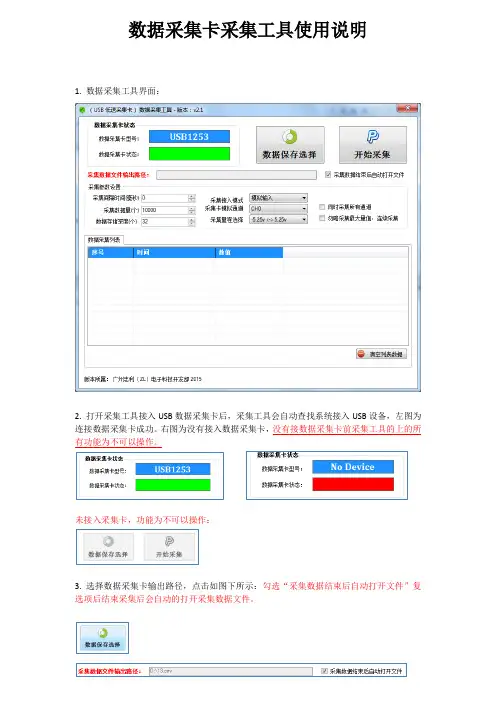
数据采集卡采集工具使用说明1. 数据采集工具界面:2. 打开采集工具接入USB数据采集卡后,采集工具会自动查找系统接入USB设备,左图为连接数据采集卡成功。
右图为没有接入数据采集卡,没有接数据采集卡前采集工具的上的所有功能为不可以操作。
未接入采集卡,功能为不可以操作:3. 选择数据采集卡输出路径,点击如图下所示:勾选“采集数据结束后自动打开文件”复选项后结束采集后会自动的打开采集数据文件。
4. 采集参数设置:A.采集间隔时间(毫秒):采集每次数据点之间的等待时间设置,设置为0表示不等待连续采集数据。
B.采集数据量(个):最大采集数量值,采集到最大值后程序自动停止结束。
勾选“勿略采集最大量值,连续采集”复选框后此设置将无效。
采集结束在点击“停止采集”按键后结束。
C.数据存储深度(个):存储深度主要解决实时显示数据软件所占用的时间,存储深度值越大显示数据越慢,此显示速度慢不影响正常采集速度,只是影响显示速度。
如采集时频率比较慢时需要设置采集间隔时间,把存储深度设置为1表示实时值。
D.采集接入模式:采集模拟分为三种:模拟输入(单极性),差分输入,真双极输入。
模拟输入只能采集大于0V以上的电压值,不能采集负电压。
差分输入可以测试正负电压,测试正负电压需要按差分方式接线,差分方式接线与地线无关。
真双极输入可以测试正负电压,可以直接测试负电压。
采集工具会根据采集卡类型显示不同的输入模式,工具只会显示支持的模式选择项。
详细支持输入模式请参考产品说明书参数规格。
E.采集卡输入通道:输入通道表示采集卡指定的采集通道,不同型号采集有不同数量的采集通道。
采集卡支持:单通道采集和全通道采集功能。
全通道采集功能可以勾选“同时采集所有通道”复选框。
F.采集量程选择:不同类型采集卡支持不同的量程选择,详细参数可以参考用户说明。
5.清空列表数据点击“清空列表数据”按键后会清除列表数据,注意:清空后的数据不可恢复:6.数据采集:点击“开始采集”按键后采集工具自动开始采集数据,点击“停止采集”后程序自动停止并保存采集数据。
数据采集器使用说明书一、产品介绍数据采集器是一种用于收集和记录数据的设备。
它可以通过各种传感器收集环境参数、设备状态等各类数据,并将其存储在内部存储器中。
数据采集器具有小巧方便的特点,可广泛用于科学研究、环境监测、农业、工业控制等领域。
二、功能特点1. 多种传感器支持:数据采集器可连接多种类型的传感器,如温度传感器、湿度传感器、压力传感器等,以便采集不同参数的数据。
2. 数据存储:数据采集器内置高容量存储器,可持久存储采集到的数据,以备后续分析和处理。
3. 数据传输:采集器支持多种数据传输方式,如USB、Wi-Fi、蓝牙等,可将采集到的数据传输至外部设备或云平台,方便数据管理和共享。
4. 实时监控:数据采集器配备LCD显示屏,可实时显示采集到的数据,实现数据的即时监控。
5. 多种采集模式:采集器支持自动采集、定时采集、手动采集等多种工作模式,满足不同应用场景的需求。
三、使用说明1. 连接传感器:首先,将数据采集器与传感器进行连接。
根据传感器的接口类型,插入相应的传感器接口。
确保连接牢固,避免松动引起数据采集错误。
2. 开机设置:将数据采集器接入电源,按下电源开关进行开机。
在开机界面,可以进行各项设置,如日期时间设定、采集参数设定等。
按照提示进行操作,并确认设置无误后,保存设置并重启采集器。
3. 选择采集模式:根据实际需求选择采集模式。
若需要实时监控,选择自动采集模式;若需要定时采集,设定采集时间间隔;若需要手动采集,通过按键控制采集动作。
4. 数据传输:一旦采集到数据,可通过USB接口将数据导出到电脑或其他外部设备中。
也可以通过无线传输方式,将数据传输至其他设备或云平台。
操作时,请务必按照相应的传输方式进行操作,确保数据的安全和准确性。
5. 数据管理:为了方便管理和查阅,可以在采集器上设定相关的数据标签,如采集地点、项目名称等。
将数据按照不同标签进行分类存储,方便后续的数据处理和分析。
四、注意事项1. 使用前请阅读使用说明书,确保正确操作。
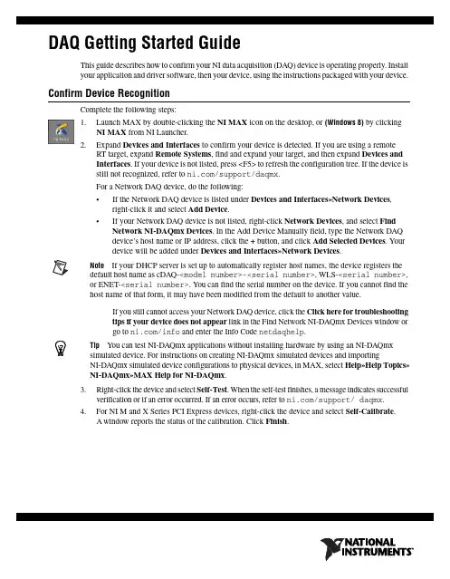
DAQ Getting Started GuideThis guide describes how to confirm your NI data acquisition (DAQ) device is operating properly. Install your application and driver software, then your device, using the instructions packaged with your device. Confirm Device RecognitionComplete the following steps:unch MAX by double-clicking the NI MAX icon on the desktop, or (Windows8) by clickingNI MAX from NI Launcher.2.Expand Devices and Interfaces to confirm your device is detected. If you are using a remoteRT target, expand Remote Systems, find and expand your target, and then expand Devices andInterfaces. If your device is not listed, press <F5> to refresh the configuration tree. If the device isstill not recognized, refer to /support/daqmx.For a Network DAQ device, do the following:•If the Network DAQ device is listed under Devices and Interfaces»Network Devices, right-click it and select Add Device.•If your Network DAQ device is not listed, right-click Network Devices, and select Find Network NI-DAQmx Devices. In the Add Device Manually field, type the Network DAQdevice’s host name or IP address, click the + button, and click Add Selected Devices. Yourdevice will be added under Devices and Interfaces»Network Devices.Note If your DHCP server is set up to automatically register host names, the device registers thedefault host name as cDAQ-<model number>-<serial number>, WLS-<serial number>,or ENET-<serial number>. You can find the serial number on the device. If you cannot find thehost name of that form, it may have been modified from the default to another value.If you still cannot access your Network DAQ device, click the Click here for troubleshootingtips if your device does not appear link in the Find Network NI-DAQmx Devices window orgo to /info and enter the Info Code netdaqhelp.Tip You can test NI-DAQmx applications without installing hardware by using an NI-DAQmxsimulated device. For instructions on creating NI-DAQmx simulated devices and importingNI-DAQmx simulated device configurations to physical devices, in MAX, select Help»Help Topics»NI-DAQmx»MAX Help for NI-DAQmx.3.Right-click the device and select Self-Test. When the self-test finishes, a message indicates successfulverification or if an error occurred. If an error occurs, refer to /support/ daqmx.4.For NI M and X Series PCI Express devices, right-click the device and select Self-Calibrate.A window reports the status of the calibration. Click Finish.Configure the Device SettingsSome devices, such as the NI-9233 and some USB devices, do not need properties for configuringaccessories, RTSI, topologies, or jumper settings. If you are installing only devices without configurable properties, skip to the next step. Configure each device with configurable settings that you install:1.Right-click the device name and select Configure. Be sure to click the device name under thefolder for the system (My System or Remote Systems) and NI-DAQ API in which you want tocontrol the device.For Network DAQ devices, click the device name and then the Network Settings tab to configurenetwork settings. For additional information on configuring Network DAQ devices, refer to yourdevice documentation.2.Configure the device properties.•If you are using an accessory, add the accessory information.•For IEEE 1451.4 transducer electronic data sheet (TEDS) sensors and accessories, configure the device and add the accessory as previously described. Click Scan for TEDS. To configureTEDS sensors cabled directly to a device, in MAX, right-click the device under Devices andInterfaces and select Configure TEDS.3.Click OK to accept the changes.Install Signal Conditioning or Switch DevicesIf your system includes SCXI signal conditioning modules, Signal Conditioning Components (SCC)such as SC carriers and SCC modules, terminal blocks, or switch modules, refer to the getting started guide for the product to install and configure the signal conditioning or switch hardware.Attach Sensors and Signal LinesAttach sensors and signal lines to the terminal block or accessory terminals for each installed device.You can find device terminal/pinout locations in MAX, the NI-DAQmx Help, or the devicedocumentation. In MAX, right-click the device name under Devices and Interfaces, and selectDevice Pinouts.For information about sensors, refer to /sensors. For information about IEEE 1451.4 TEDS smart sensors, refer to /teds. If you are using SignalExpress, refer to Use NI-DAQmx withYour Application Software.Run Test PanelsUse the MAX test panel as follows.1.In MAX, expand Devices and Interfaces or Devices and Interfaces»Network Devices.2.Right-click the device to test, and select Test Panels to open a test panel for the selected device.3.Click the tabs at the top and Start to test the device functions, or Help for operating instructions.4.If the test panel displays an error message, refer to /support.5.Click Close to exit the test panel.DAQ Getting Started Take an NI-DAQmx MeasurementNI-DAQmx Channels and TasksA physical channel is a terminal or pin at which you can measure or generate an analog or digital signal.A virtual channel maps a name to a physical channel and its settings, such as input terminal connections,the type of measurement or generation, and scaling information. In NI-DAQmx, virtual channels areintegral to every measurement.A task is one or more virtual channels with timing, triggering, and other properties. Conceptually, a taskrepresents a measurement or generation to perform. You can set up and save configuration information in a task and use the task in an application. Refer to the NI-DAQmx Help for complete information about channels and tasks.Use the DAQ Assistant to configure virtual channels and tasks in MAX or in your application software. Configure a Task Using the DAQ Assistant from MAXComplete the following steps to create a task using the DAQ Assistant in MAX:1.In MAX, right-click Data Neighborhood and select Create New to open the DAQ Assistant.2.In the Create New window, select NI-DAQmx Task and click Next.3.Select Acquire Signals or Generate Signals.4.Select the I/O type, such as analog input, and the measurement type, such as voltage.5.Select the physical channel(s) to use and click Next. the task and click Finish.7.Configure individual channel settings. Each physical channel you assign to a task receives a virtualchannel name. To modify the input range or other settings, select the channel. Click Details forphysical channel information. Configure the timing and triggering for your task. Click Run. Use NI-DAQmx with Your Application SoftwareThe DAQ Assistant is compatible with version 8.2 or later of LabVIEW, version 7.x or later ofLabWindows™/CVI™ or Measurement Studio, or with version 3 or later of SignalExpress.SignalExpress, an easy-to-use configuration-based tool for data logging applications, is at Start»AllPrograms»National Instruments»NI SignalExpress or (Windows8) NI Launcher.To get started with data acquisition in your application software, refer to the tutorials:Application Tutorial LocationLabVIEW Go to Help»LabVIEW Help. Next, go to Getting Started with LabVIEW»GettingStarted with DAQ»Taking an NI-DAQmx Measurement in LabVIEW.LabWindows/CVI Go to Help»Contents. Next, go to Using LabWindows/CVI»Data Acquisition»Taking anNI-DAQmx Measurement in LabWindows/CVI.Measurement Studio Go to NI Measurement Studio Help»Getting Started with the Measurement StudioClass Libraries»Measurement Studio Walkthroughs»Walkthrough: Creating aMeasurement Studio NI-DAQmx Application.SignalExpress Go to Help»Taking an NI-DAQmx Measurement in SignalExpress.© National Instruments3DAQ Getting Started GuideExamplesNI-DAQmx includes example programs to help you get started developing an application. Modifyexample code and save it in an application, or use examples to develop a new application or add example code to an existing application.To locate LabVIEW, LabWindows/CVI, Measurement Studio, Visual Basic, and ANSI C examples, go to /info and enter the Info Code daqmxexp. For additional examples, refer to .To run examples without hardware installed, use an NI-DAQmx simulated device. In MAX, selectHelp»Help Topics»NI-DAQmx»MAX Help for NI-DAQmx and search for simulated devices. TroubleshootingIf you have problems installing your software, go to /support/daqmx. For hardwaretroubleshooting, go to /support and enter your device name, or go to /kb.If you need to return your National Instruments hardware for repair or device calibration, refer to / info and enter the Info Code rdsenn to start the Return Merchandise Authorization (RMA) process.Go to /info and enter rddq8x for a complete listing of the NI-DAQmx documents and their locations.More InformationAfter you install NI-DAQmx, the NI-DAQmx software documents are accessible from Start»All Programs»National Instruments»NI-DAQ»NI-DAQmx document title or(Windows8) NI Launcher. Additional resources are online at /gettingstarted.You can access online device documentation by right-clicking your device in MAX and selecting Help»Online Device Documentation. A browser window opens to /manuals with the results of a search for relevant device documents. If you do not have Web access, documents for supported devices are included on the NI-DAQmx media.Worldwide Technical SupportFor support information, refer to /support for access to everything from troubleshooting and application development self-help resources to email and phone assistance from NI ApplicationEngineers. Visit /zone for product tutorials, example code, webcasts, and videos.Visit /services for NI Factory Installation Services, repairs, extended warranty, calibration, and other services.To ensure measurement accuracy, NI factory calibrates all applicable hardware and issues a BasicCalibration certificate, which you can get online at /calibration.Visit /training for self-paced training, eLearning virtual classrooms, interactive CDs,Certification program information, or to register for instructor-led, hands-on courses at locations around the world.For support available at the National Instruments worldwide offices, visit , or contact your local office at /contact. National Instruments corporate headquarters is located at 11500 NorthMopac Expressway, Austin, Texas, 78759-3504.DAQ Getting Started Refer to the NI Trademarks and Logo Guidelines at /trademarks for more information onNational Instruments trademarks. Other product and company names mentioned herein are trademarksor trade names of their respective companies. For patents covering National Instrumentsproducts/technology, refer to the appropriate location: Help»Patents in your software, thepatents.txt file on your media, or the National Instruments Patent Notice at /patents.You can find information about end-user license agreements (EULAs) and third-party legal notices inthe readme file for your NI product. Refer to the Export Compliance Information at /legal/export-compliance for the National Instruments global trade compliance policy and how toobtain relevant HTS codes, ECCNs, and other import/export data.© 2003–2013 National Instruments. All rights reserved.373737H-01Jul13。
EDAD2001系列采集装置 软件使用说明书北京煜邦电力技术有限公司目录前言 (1)1、程序的运行环境 (1)2、程序的运行 (1)3、程序的使用和功能简介 (2)3.1界面介绍 (2)3.2菜单介绍 (3)3.3工作窗口说明 (5)3.3.1 “数据显示”工作窗口 (5)3.3.2 “设备定义”工作窗口 (6)3.3.3 “参数设置”工作窗口 (10)3.3.4 “数据查询”工作窗口 (11)3.3.5 “召测量查询”工作窗口 (13)3.3.6 “事件查询”工作窗口 (14)3.3.7 “直方图窗”工作窗口 (15)3.3.8 “更改密码”对话框 (16)3.3.9 “通信口设置”对话框 (16)3.3.10 “IP地址设置”对话框 (19)3.3.11 “召测设置”对话框 (21)3.3.12 “设置时间”对话框 (22)前言本文描述了EDAD2001系列电能数据综合采集装置(简称采集器)软件的使用和设置方法。
EDAD2001系列电能数据综合采集装置包括EDAD2001、EDAD2001-C和EDAD2001-H等三款采集装置。
这三种采集装置的软件除了界面的标题分别标识不同型号之外,在使用方法上几乎完全相同,本文以EDAD2001-C电能数据综合采集装置为例进行介绍。
在涉及到软件名称的地方一律以“EDAD2001软件”来描述。
1、程序的运行环境EDAD2001软件是一个自带中文字库和汉字输入法的全中文界面程序,可以不依赖于其他的中文平台而独立运行。
2、程序的运行采集器上电后程序自动运行,无需用户干预。
程序运行后,自动开始初始化操作,该过程可能需要几秒到十几秒的时间,视设备及软件配置的不同而有所差异。
在初始化过程中,程序会显示一个对话框来提示进度,如图2-1所示。
如果初始化过程没有发生错误,程序将正常执行。
如果初始化程序检测到异常情况,程序将弹出严重错误提示框,并在15秒钟后自动重启以试图恢复正常。
第三次全国经济普查PDA数据采集软件使用手册(使用京云万峰平台)目录一、前言 (1)二、系统安装与环境要求 (1)(一)系统环境要求 (1)(二)系统安装过程 (1)1.安装包准备与检查 (1)2.安装步骤 (1)三、PDA普查数据采集 (3)(一)PDA登录 (3)(二)普查任务准备 (5)(三)核查和数据采集 (6)1.地址点采集 (6)2.单位实地核查及采集 (9)3.个体经营户采集 (16)(四)普查数据查看与修改 (18)1.地址点数据查看与修改 (19)2.单位数据查看与修改 (20)3.个体户数据查看与修改 (21)(五)数据上报 (22)一、前言1、移动终端管理系统2、数据处理平台3、联想数据采集软件(PDA数据采集软件)二、系统安装与环境要求(一)系统环境要求(二)系统安装过程1.安装包准备与检查打开文件夹管理器检查:软件安装包“三经普PDA数据采集LVx.x.x版软件(联想)”是否存在(图2-1-1):图2-1安装文件若软件安装包不存在,将软件安装包拷贝至PDA根目录。
2.安装步骤(1)点击,开始安装。
界面显示如下(图2-2):图2-2安装开始界面(2)安装过程中,操作员按照提示点击下一步,安装工具默认安装,界面显示如下(图2-3):(3)点击完成按钮,完成安装过程,界面显示如下(图2-4):图2-4安装完成界面三、PDA普查数据采集(一)PDA登录在PDA的应用列表中,点击程序图标打开程序,进入程序的注册界面,界面显示如下(图3-1):图3-1PDA注册界面第一次打开程序时,需要注册,点击“”按钮,打开“移动终端管理系统”应用进行注册。
注册完成后,退出“移动终端管理系统”与“PDA数据采集”应用,再次点击程序图标“PDA数据采集”,打开程序,进入登录界面如下(图3-2):图3-2PDA登录界面输入用户名、密码,登录后进入主界面,显示如下(图3-3):图3-3软件操作主界面主要功能:数据采集、数据同步、进度监测、检查更新,以及应用指南、工具条。
数据采集系统DAQ970A/DAQ973A此手册提供 Keysight DAQ970A/DAQ973A 数据采集系统的操作说明。
最新版本请始终参考英文版。
用户指南声明6版权声明6手册文档号6版本6发布者6软件修订版6担保说明7技术许可7限制性权限声明7废弃电子电气设备(WEEE)7符合性声明8安全和法规信息9安全注意事项9安全符号和法规标记10韩国A类EMC声明11产品法规及合规性12环境条件121仪器简介13仪器概览14前面板概览15仪器信号器16后面板概览17插件模块概览18尺寸图19远程接口配置20 Keysight IO Libraries Suite20 GPIB设置(仅限DAQ973A)20 LAN设置21 LAN服务27设置为默认值27 LAN重置27 Web界面28关于IP地址和点号的详细信息28 USB设置29技术连接详细信息30 LAN配置过程31固件更新33联系是德科技34 2快速入门35准备要使用的仪器36模块线路连接和安装37安装模块37卸载模块39连接电源和I/O电缆40打开仪器40开机自检40关闭仪器40使用内置帮助系统41查看帮助主题列表41查看前面板键的帮助信息422Keysight DAQ970A/DAQ973A用户指南查看仪器信息42调整提手43在机架中安装仪器44 Keysight BenchVue数据采集(DAQ)软件46 BenchVue数据采集(DAQ)软件许可46 3特征与功能47系统概述48数据采集系统概述48信号发送和切换52测量输入54多功能模块58控制输出59前面板菜单参考61 [Scan/Start]键63 [Monitor]菜单64数字65条形仪表66趋势图67直方图68 [Home]菜单70数据采集模式70 Strain offset71 Alarm output73帮助主题73 User settings74 [View]菜单77 Scan模式中的[View]菜单77 DMM Digitize或Digitizer模式中的[View]菜单82电源分析90 [View]菜单状态93 [Channel]菜单94多路复用模块:测量值94多路复用模块:开关模式130 DAQM907A-多功能模块133 DAQM909A-4通道24位数字转换器模块141被计算通道146使用外部仪器扫描151为通道添加标签152 [Interval]菜单153 Scan模式中的[Interval]菜单153 DMM Digitize模式中的[Interval]菜单156 Digitizer模式中的[Interval]菜单159 [Math]菜单163 mX+b标定163 %标定164 dBm标定164 dB标定165 [Copy]菜单166从单个通道复制/粘贴到单个通道(一对一)166从单个通道复制/粘贴到多个通道(一对多)167从多个通道复制/粘贴到多个通道(多对多)168 Keysight DAQ970A/DAQ973A用户指南3[Alarm]菜单169配置多路复用模块上的警报限值169配置多功能模块上的警报限值170警报限值指示171 [Utility]菜单173 Self Test173 Autocal173 Calibrate174 Security175 Admin175 [Module]菜单176 Scan List176 Card Reset177 Module Label177 Relay Cycle178 [Save Recall]菜单179 Manage Files179 Save180 Recall181设置为默认值181 Log to USB182 Save to USB185 Web界面187“Control Instrument”页面188“Configure LAN”页面188“Help”页面189模块概述190 DAQM900A20通道FET多路复用模块191 DAQM901A20通道衔铁式多路复用模块193 DAQM902A16通道舌簧式多路复用模块195 DAQM903A20通道制动器/通用开关模块197 DAQM904A4x8双线矩阵开关199 DAQM905A1:4双射频多路复用(50Ω)模块201 DAQM907A多功能模块203 DAQM908A40通道单端多路复用器206 DAQM909A4通道24位数字转换器模块208 4测量教程211系统电缆和连接212电缆规格212接地技术214屏蔽技术215高电平信号和低电平信号的分隔215系统电缆误差源215测量的基本知识219内部DMM219温度测量220直流电压测量228交流电压测量232电流测量238电阻测量240应变仪测量243 4Keysight DAQ970A/DAQ973A用户指南频率和周期测量246电容测量248数字化测量249电平触发251低电平信号的多路复用和切换252单线(单端)多路复用器252双线多路复用器253四线多路复用器253信号发送和多路复用254多路复用和切换中的误差源254制动器和通用开关256矩阵切换259 RF信号多路复用261多功能模块263数字输入263数字输出264使用外部上拉电阻265驱动外部开关265积算器266积算器误差267模拟输出(DAC)267继电器的使用寿命和预防性维护269Keysight DAQ970A/DAQ973A用户指南5声明声明版权声明©是德科技2019-2022根据美国和国际版权法,未经Keysight Technologies事先允许和书面同意,不得以任何形式或通过任何方式(包括电子存储和检索或翻译为其他国家或地区的语言)复制本手册中的任何内容。
1.概述1.1 引言该数据采集器采用当代微电子技术,对电力设备运行中的数据进行记录、存储、显示。
具有工作可靠、操作简单、数据便于收集和计算机分析等特点。
U盘作为新型移动存储设备,以体积小、速度高、抗震动、通用性强的特点倍受青睐。
该数据采集器可将采集的数据直接存储到普通U盘中。
数据采集完毕后,用户可直接从采集器上取下U盘,利用计算机方便地实现对采集数据的收集和分析处理。
1.2 系统组成该数据采集器主要有五部分组成:电源单元、交流采样单元、处理单元、U盘存储单元、显示单元,框图如下图1所示。
图1 数据采集器框图1.3 功能介绍1.3.1 电力数据采集数据采集器能采集、存储、显示电力设备运行中的实时三相电压、三相电流、有功功率、无功功率、功率因素、U盘读取之后的电能累计值。
电能数据保存时带有时标。
1.3.2 数码显示该数据采集器面板采用数码管分别进行功能和数值显示。
功能显示为2位数码管显示。
功能显示码“UA”、“UB”、“UC”、“IA”、“IB”、“IC”、“pt”、“qt”、“EA”、“PF”分别代表“A相电压”、“B相电压”、“C相电压”、“A相电流”、“B相电流”、“C相电流”、“有功功率”、“无功功率”、“电能”、“功率因素”。
用户可以使用功能按键、增加按键、减少按键使功能显示码循环显示。
数值显示为4位数码管显示。
当电能数值超过4位数时,功能显示码仅用左边的数码管显示为“E”,功能显示码右边的数码管和4位数值显示数码管一起构成5位数码管来显示当前的电能数值。
1.3.3 数据管理和存储数据采集器每隔15分钟将电力运行数据存储在处理单元的控制芯片内部flash里面。
用户定期(建议半个月一次,最长一个月)可以使用U盘对存储数据进行读取,以txt文件形式存储,以当前的月日时分信息进行命名。
读取时,U盘读取指示灯LUSB点亮,读取操作完成后,U盘读取指示灯LUSB熄灭,控制芯片内部flash中数据将被清空。
G3-Logger-4G, S3-Logger数据采集器用户手册锦浪科技股份有限公司目录1.1 目的三、产品描述1………………………………………………………………………………………………………………………………………………………………………………………………13……………………………………………………………………………………………………………………………………………………………………………………………………………………………………………………………………………………………………………………………………………………………………………………………………………………………………………………………………………………………………………………………………………………………………………………………71.2 说明四、安装流程5.1 设备拆装5.2 设备安装………………………………………………………………………………………………………………………………………………………………………………………………………………………………………………………………………………………………………………………………………………………………………………………………………………………………………………………………………………………………………………………………………………………………………………888五、机械安装1.3 符号说明……………………………………………………………………………………………………………………………………………………………………………………1二、安全须知……………………………………………………………………………………………………………………………………………………………………………………………2六、电气连接……………………………………………………………………………………………………………………………………………………………………………………………10七、工程配置……………………………………………………………………………………………………………………………………………………………………………………………12……………………………………………………………………………………………………………………………………………………………………………………………12八、日常维护……………………………………………………………………………………………………………………………………………………………………………………………20九、常见故障…………………………………………………………………………………………………………………………………………………………………………………………………21十、附录………………………………………………………………………………………………………………………………………………………………………………………………………………22一、关于本手册………………………………………………………………………………………………………………………………………………………………………………………1 软件配置3.1 产品介绍3…………………………………………………………………………………………………………………………………………………………………………………………3…………………………………………………………………………………………………………………………………………………………………………………………3.2 应用场景3.3 外观…………………………………………………………………………………………………………………………………………………………………………………………………43.4 电源接线示意图4………………………………………………………………………………………………………………………………………………………………………5……………………………………………………………………………………………………………………………………………………………………………3.5 通讯端子说明3.6 指示灯说明……………………………………………………………………………………………………………………………………………………………………………………6 产品规格书…………………………………………………………………………………………………………………………………………………………………………………………22一、关于本手册本手册主要适用于锦浪科技股份有限公司以下数据采集器G3-Logger-4G, S3-Logger1.1 目的向读者提供G3-Logger-4G, S3-Logger的详细产品信息及安装操作维护说明。
NLS-PT80系列数据采集器用户手册声明请您在使用本手册描述的产品前仔细阅读手册的所有内容,以保障产品的安全有效地使用。
阅读后请将本手册妥善保存以备下次使用时查询。
请勿自行拆卸终端或撕毁终端上的封标,否则福建新大陆自动识别技术有限公司不承担保修或更换终端的责任。
本手册中的图片仅供参考,如有个别图片与实际产品不符,请以实际产品为准。
对于本产品的改良更新,新大陆自动识别技术有限公司保留随时修改文档而不另行通知的权利。
本手册包含的所有信息受版权的保护,福建新大陆自动识别技术有限公司保留所有权利,未经书面许可,任何单位及个人不得以任何方式或理由对本文档全部或部分内容进行任何形式的摘抄、复制或与其它产品捆绑使用、销售。
本手册中描述的产品中可能包括福建新大陆自动识别技术有限公司或第三方享有版权的软件,除非获得相关权利人的许可,否则任何单位或者个人不能以任何形式对前述软件进行复制、分发、修改、摘录、反编译、反汇编、解密、反向工程、出租、转让、分许可以及其它侵犯软件版权的行为。
福建新大陆自动识别技术有限公司对本声明拥有最终解释权。
版本记录版本号版本描述发布日期V 1.0 初始版本。
2012-04-11目录第一章关于本手册 (1)介绍 (1)注意事项 (1)产品参数 (2)软硬件版本 (3)章节描述 (3)获取更多 (3)服务指南 (3)第二章开始使用 (5)介绍 (5)拆封 (5)标准配置 (5)选购配置 (5)PT80 使用入门 (5)安装电池 (5)移除电池 (6)安装手提带 (6)PT80 设备启动 (6)PT80 设备休眠 (6)PT80 设备关机 (7)PT80设备充电 (7)指示灯与键盘 (8)第三章使用PT80 设备 (9)介绍 (9)系统菜单 (9)运行程序 (9)系统设置 (9)用户程序设置 (10)系统时间设置 (10)通信方式设置 (11)读码测试 (15)自检测试 (16)系统信息 (20)第四章数据传输 (22)介绍 (22)PT80设备与PC的连接 (22)数据传输 (22)USB 传输方式 (22)HID 键盘 (25)U盘 (26)U盘只读 (27)串口模式 (28)PT80设备上串口设置 (28)PC端虚拟串口驱动安装 (29)虚拟串口使用 (31)串口下载模式 (33)WIFI传输方式 (34)第五章常见故障的排除 (38)无法开机 (38)液晶不显示 (38)充电后使用不长时间就提示电量不足 (38)USB通讯无法进行 (38)死机 (38)充电时,指示灯不亮 (38)BlueTooth连接失败 (38)WIFI连接失败 (38)无法识读条码 (38)介绍本手册将详细介绍如何使用PT80 数据采集器以及它的配件。
量表数据采集程序说明
(适用系统XP,2000,VISTA)
一.把量表用数据线连接到电脑,打开光盘数据包里面的“新版电脑采集程序”文件夹,再打开里面的“中文采集软件”文件夹,然后打开“FYData.exe”,出现如下窗口:
1→“打开”:打开原保存的测试数据记录;2→“保存”:保存当前的测试数据;
3→“预览”:打印预览;4→“打印”:打印;
5→“连接”:将量表的数据接口与计算机连接上;
→“断开连接”:断开连接;
6→“提示”:数据超差时,出现“嘟”提示音;
→“无提示”:数据超差时不提示;
7→“设置”:设置;详细说明见下文;
8→“退出”: 退出软件;
9→“清除”:删除所有已采集的数据;
10→“删除”:删除当前光标指定的数据;
11→“自动”:自动采样(采样时间在“setup”中设置);
12→“手动”:手动采样,按下此按钮,采样一次;
13→“序号”:采样序列号;14→“数据值”:采样数据值;
15→“误差值”:误差值=Value(数据值)-STD(标准值);
16→“P”:超差提示,“+NG”:超上公差;“-NG”:超下公差;“OK”:
在公差范围内,合格;
16→“4800”:显示的值是当前与计算机通信的连接速率;
17→“COM1”:显示与计算机连接的串口;
二.点击设置,出现如下界面:
操作者可以不填,自动采集间隔为2000毫秒每次,端口为连接电脑端口
三.点击公差进入公差设置,
单位:可选公制,英制
标准值:不能输入负数
上公差:输入上公差值
下公差:输入下公差值
注:拔出或者更换数据线时记得先点击“断开”,否则下次连接可能出现死机或者运行缓慢的情况。