霍尼韦尔CP-IPC控制器
- 格式:pdf
- 大小:348.07 KB
- 文档页数:3

HONEYWELL楼控部分产品型号、参数及产地产品型号说明产地监控中心基本软件EBI 基本软件 12个读卡器/250点澳大利亚EBI 基本软件 12个读卡器/500点澳大利亚EBI 扩展软件 250澳大利亚EBI 扩展软件 500澳大利亚EBI 扩展软件 750澳大利亚EBI 扩展软件 1000澳大利亚EBI 扩展软件 1250澳大利亚EBI 扩展软件 1500澳大利亚EBI 扩展软件 1750澳大利亚EBI 扩展软件 2000澳大利亚EBI 扩展软件 2750澳大利亚EBI 扩展软件 3000澳大利亚EBI 扩展软件 3250澳大利亚EBI 扩展软件 3500澳大利亚EBI 扩展软件 3750澳大利亚EBI 扩展软件 4000澳大利亚EBI 扩展软件 4250澳大利亚EBI 扩展软件 4500澳大利亚EBI 扩展软件 5000澳大利亚BA服务器附件功能软件EBI-OPDASPTS数据点分布式数据库构架软件许可澳大利亚EBI-OPALMPAG报警传护软件许可澳大利亚EBI-OPWEBTL Web Toolkit澳大利亚EBI-OPWEBPCTL Web Point Control澳大利亚工作站附件软件EBI-XXCAL附件的一个浏览器工作站软件许可澳大利亚开放式软件许可EBI-IFXLDIR Excel 5000 interface license (scantask)澳大利亚EBI-IFBACDIRCL Bacnet 客户端软件许可澳大利亚EBI-SVBACNET Bacnet 服务器软件许可澳大利亚EBI-IFOPCCL OPC 客户端软件许可澳大利亚EBI-SVOPCDAS OPC 服务器软件许可澳大利亚SWEBI-IFMODIC MODBUS 接口软件许可澳大利亚XL5000 C-BUS通讯接口Q7055A1007BNA-1C,C-Bus-网络通讯卡 (1条C-Bus)德国Q7055A1015BNA-2CS,C-Bus-网络通讯卡 (2条C-Bus)德国直接数字控制器XL800控制器。

ComfortPoint 系列(即
Excel8000)
EXCEL5000系列WEBs 系统网络图
系统网络结构基于标准以太网/局域网架构。
系统采用两层网
络结构:上层管理网通讯协议为BACnet
TCP/IP,下层控制网通讯协议为MS-TP。
支持点
到点通讯
基于总线的系统架构。
系统为两层网络结构:管理
网采用TCP/IP协议,下层控制网采用C+Lon总线。
基于总线的系统架构,系统为三层结构,第一层网
络,下两层LON总线。
系统通讯协议BACnet TCP/IP 控制网络支持C-BUS, LonWorks协议;专用控制器
支持LonWorks;XL Web通讯协议为LonWorks且
支持第三方BACnet接口。
第一层(管理层)采用TCP/IP协议,控制网和现场
网采用Lonmark协议。
控制器的CPU32位微处理器XL800/XL50采用16位微处理器。
XL Web 控制器采用32位微处理器16位微处理器霍尼韦尔产品性能。


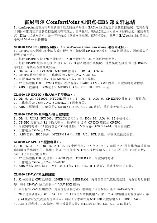
霍尼韦尔ComfortPoint知识点-HBS郑文轩总结1、comfortpoint是霍尼韦尔最新基于以太网技术并使用BACnet协议的建筑设备监控系统。
它完全符合国际标准对建筑设备监控系统具有管理层、自动化层、现场层三层结构的网络结构要求,采用分布式(DSA)局域网结构,是一套开放式计算机网络系统,能够和其他厂商基于BACnet协议的第三方系统和Modbus设备相连。
进程间通信)):XL8000 CP-IPC(网络控制器网络控制器))(Inter-Process Communication,进程间通信1、CP-IPC本身提供24个输入输出硬件点,如使用CP-EXPIO或CP-DIO扩展模块,则可最大扩展到128个点。
2、每台CP-IPC支持128个硬件点,1500个软件点,64个闭环控制回路。
3、每台CP-IPC最多可连接15台CP-EXPIO输入输出扩展模块,这些模块连接在同一条RS485总线上,导轨或者壁挂式安装。
4、DI:6,AI:8(PT1000、NTC20K皆可),DO:4,AO:6。
5、CP-IPC是独立供电,工作电压24Vac±20%,50/60HZ。
6、内置BACnet路由器,支持Modbus协议,可自由编程。
7、32位高性能CPU,32MB数据、程序存储,256KB RAM,4MB内存,内置实时时钟程序。
8、ABS工程塑料,IP20防护,MTBF>11.4年,CE、UL、BTL认证。
XL8000 CP-EXPIO(输入输出扩展模块):输入输出扩展模块):1、DI:6,AI(PT1000、NTC20K皆可):8,DO:4,AO:6。
CP-EXPIO具有24个硬件点。
2、工作电压24Vac±20%,50/60HZ,16进制开关。
3、ABS工程塑料,IP20防护,MTBF>11.4年,CE、UL认证,导轨或者壁挂式安装。
XL8000 CP-DIO(数字输入/输出控制器):1、DI:8,UI/AI(PT1000、NTC20K皆可):8,DO:16,AO:0。

比较项目WEBs ComfortPoint系列(即Excel8000)系统网络图系统网络结构基于标准以太网/局域网架构。
上位机工作站和网络控制器WEB8000均为Niagara站点,基于以太网通讯,平级(自带WEBSERVER,小系统可不配上位机,上位机平台故障时可应急访问WEB8000,确保系统可靠性)。
第二层为现场控制器层,采用以太网控制器8445,通讯速率可达100Mbps。
优势:组网结构灵活、可扩展性强、通讯速度快、网络稳定。
系统采用三层网络结构:上位机层工作站基于以太网与网络控制器通讯,管理网网络控制器往上是BACnet TCP/IP,向下是BACnet MS/TP,现场设备层基于RS485结构,通讯协议为BACnet MS/TP,通讯速率最高76.8kbps。
不足:传统总线结构、通信速率相对较慢、组网不够灵活,不易扩展。
系统通讯协议•采用全以太网结构,BACnet IP协议•以太网+现场RS485结构(BACnet MS/TP,补充部分不方便走网络的区域)。
通常采用网络控制器BACnet TCP/IP通讯,下层通过BACnetMS/TP组网方式。
要实现全以太网结构需要全部采用CP-IPC+扩展IO方式实现,造价非常高。
控制器的CPU •高性能TIAM3352,1000MHz ARM Cortex TM-A8处理器,1G内存,4G闪存,内置WIFI、USB接口•高性能32位CPU优势:内存及存储容量大网络控制器CP-IPC:32位CPU,32M RAM,32MFlash现场控制器CP-SPC:32位CPU,32K RAM,256K Flash网络连接直接以太网/局域网连接;网络链路出现故障时只影响单个控制器,网络速率10/100MBps 上层CP-IPC以以太网/局域网连接;现场控制器层通过BACnet MS/TP总线连接,最高传输速率76.8KBps,总线上控制器节点有限制,且当总线链路出现断路时,会影响到多台控制器。

2017-HBS-0528-CN© 2017霍尼韦尔国际有限公司HBS 官方微信网址: 邮件: hbschina@ 维保服务热线: 400 920 2288霍尼韦尔智能建筑与家居集团建筑智能系统部中国上海浦东新区张江高科技园区环科路555号1号楼电话: (86-21) 8038 8600传真: (86-21) 6024 6073邮编: 201203北京办事处北京市朝阳区酒仙桥路14号兆维工业园甲一号楼5层电话: (86-10) 5669 6000传真: (86-10) 5756 0509邮编: 100015天津办事处天津市河西区解放路256号泰达大厦17层A2电话: (86-22) 5881 6607传真: (86-22) 5881 6643邮编: 300042广州办事处广州市海珠区滨江中路308号海运大厦15楼A 座电话: (86-20) 8410 1800传真: (86-20) 8410 1816邮编: 510220深圳办事处深圳市南山区东滨路4078号永新汇1号楼17、18楼电话: (86-755) 3638 1700传真: (86-755) 2518 1220邮编: 518054香港办事处香港北角英皇道255号国都广场霍尼韦尔大厦21楼电话: (852) 2331 9133传真: (852) 2953 6772澳门办事处澳门新口岸宋玉生广场249-263号中土大厦16楼F 座电话: (853) 2875-7580台湾办事处台湾新北市中和区连城路168号10楼电话: (886) 2 2245 1000传真: (886) 2 2245 3242HBS 官方微博易于集成• ComfortPoint Open 楼宇管理系统支持本地BACnet ®通信协议,能够连接其它支持BACnet ®协议的服务器或设备并与之实现交互操作。
提高用户生产效率,降低运营成本• ComfortPoint Open 配备专门设计用于移动系统访问的霍尼韦尔EasyMobile 客户端。
ComfortPoint 系列(即
Excel8000)
EXCEL5000系列WEBs 系统网络图
系统网络结构基于标准以太网/局域网架构。
系统采用两层网
络结构:上层管理网通讯协议为BACnet
TCP/IP,下层控制网通讯协议为MS-TP。
支持
点到点通讯
基于总线的系统架构。
系统为两层网络结构:管理
网采用TCP/IP协议,下层控制网采用C+Lon总线。
基于总线的系统架构,系统为三层结构,第一层网
络,下两层LON总线。
系统通讯协议BACnet TCP/IP 控制网络支持C-BUS, LonWorks协议;专用控制
器支持LonWorks;XL Web通讯协议为LonWorks
且支持第三方BACnet接口。
第一层(管理层)采用TCP/IP协议,控制网和现场
网采用Lonmark协议。
控制器的CPU32位微处理器XL800/XL50采用16位微处理器。
XL Web 控制器采用32位微处理器16位微处理器霍尼韦尔产品性能。
HD55IPKey Benefits•Outstanding image quality,720p (1280 x 720) resolution•30 fps (25 fps PAL) progressive scan •Day/Night, 3.3-12 mm VFAI lens •Camera tamper detection•Video motion detection•PSIA support •Dual digital video streams,independently configurable,H.264 and/or H.264/MJPEG•Remote firmware updates•Supports both dynamic and staticIP address assignment•Single model for surface mountapplications•Includes advanced IP locator softwareto make system setup easy•Web server for remote setup of cameravideo and network parameters•Choice of 24 V AC or PoE IEEE 802.3afClass 1 power inputs•Rugged polycarbonate dome•Wall and pendant mount kits availableSPECIFICATIONSLike all cameras in the Performance Series, the HD55IP network camera uses Honeywell technology for camera video motion detection, tamper detection, remote firmware updating and for secure storage of all camera settings. Video motion detection recognizes object motion within the field of view; then a simple on-screen notification alerts the user. Camera tamper detection notifies the user when a camera’s field of view is altered, blinded, or blurred. This ensures the video’s integrity and alerts the customer to either a live event or a system problem that is causing disruption to the video stream. Honeywell’s technology also allows users to remotely upload firmware to the camera. Setup is quick and easy and can be customized through a web client or from an NVR or DVR. The built-in web server provides password-protected access to the camera’s video and network setup.System DiagramSPECIFICATIONS*Actual bitrate is scene and motion dependent.SPECIFICATIONSAutomation and Control Solutions Honeywell Systems2700 Blankenbaker Pkwy, Suite 150Louisville, KY NOTE:Honeywell reserves the right, without notification, to make changes in product design or specifications.L/HD55IPD/D December 2012© 2011 Honeywell International Inc.HD4CHIP-PK Pendant MountHD4CHIP-WK Wall Mount。
IPC5000 Universal ProgrammableController Installation Manual57-77-25-19NoticeCopyright 2007 by HoneywellRevision 1.29June 2007Warranty / RemedyHoneywell warrants goods of its manufacture as being free of defective materials and faulty workmanship.Contact your local sales office for warrenty information. If warranted goods are returned to Honeywell during the period of coverage, Honeywell will repair or replace without charge those items it finds defective. The foregoing is Buyer’s sole remedy and is in lieu of all other warranties, expressed or implied, including those of merchantability and fitness for a particular purpose. Specifications may be changed without notice. The information we supply is believed to be accurate and reliable as of this printing. However, we assume no responsibility for its use.While we provide application assistance personally, through our literature and the Honeywell web site, it is up to the customer to determine the suitability of the product in their application.Industrial Measurement and ControlHoneywell Pte LTDHoneywell Building17 Changi Business Park Cetral 1SingaporeContents1. Overview (1)1.1 Introduction (1)1.2 Feature Summary (1)2. Installation and wiring (2)2.1 Installation environment (2)2.2 Installation precautions (3)2.3 Panel cutout dimension (4)2.4 Installation of fixed brackets (6)2.5 Making Terminal Connections (8)2.6 Terminal Array (9)2.7 Wiring (10)2.7 Terminal Allocation (25)2.8 Rear terminal (26)3. Configuration (27)3.1 Screen configuration (27)3.2 Configuration screen (28)3.3 AI SET screen (29)3.4 PWM set Screen (35)3.5 AO SET screen (37)3.6 DIO status screen (40)3.7 RANGE SET screen (45)3.8 OFFSET screen (47)3.9 Compensation set screen (48)3.10 EVENT SET (50)3.11 MODE Event set screen (53)3.12 ALARM EVENT SET screen (56)3.13 CONTROL SET screen (60)3.14 PID ZONE SET screen (63)3.15 PID CONSTANT SET screen (67)3.16 PID set screen (69)3.17 SYSTEM SET screen (71)3.18 TROUBLE SET Screen (75)3.19 TROUBLE MESSAGE set (78)3.20 NETWORK SET Screen (79)3.21 INITIALIZE screen (80)4. Specification (82)5. Model Number Interpretation (90)TablesTable 2.7.1 Minimum Recommended Wire Sizes (10)Table 2.7.2 Instrument input range code and range (21)Table 2.7.3 The function table of External switch input (Digital input) (23)Table 3.6.1 Defaults of compensation (48)Table 3.11.1 Mode Event information (53)Table 3.11.2 DO information assigned by REGISTRATION number (55)Table 3.12.1 Alarm Event Flowchart (58)Table 3.12.2 Alarm Event On/Off Operation Algorithm (59)Table 3.21.1 Initial PID parameter list (81)FiguresFig. 2.3.1 Panel cutout (4)Fig. 2.4.1 Installation of fixed brackets (6)Fig. 2.5.1 Terminal with tube (8)Fig. 2.5.2 Terminal diagram label and Terminal Block style (9)Fig. 2.6.1 Mains Power Supply (11)Fig. 2.6.2 Analog input 1 / input 2 Connections (12)Fig. 2.6.3 Control output 1 / output 2 Connections (13)Fig. 2.6.4 Digital outputs Connection (14)Fig. 2.6.5 Digital inputs Connections (15)Fig. 2.6.6 Auxiliary output 3 output 4 Connections (16)Fig. 2.6.7 RS-232C communication 9 pin Connection (16)Fig. 2.6.8 RS-232C communication 25 to 9 pin Connection (17)Fig. 2.6.9 RS422/485/Modbus Communications Option Connections (3-Wire shield) (18)Fig. 2.6.10 RS422/485/Modbus Communications Option Connections (5-Wire shield) (19)Fig. 2.8.1 Rear Terminal (26)Fig. 3.1.1 Screen switch block (27)Fig. 3.1.2 Main menu screen (28)Fig. 3.2.1 SETUP (Configuration) (28)Fig. 3.3.1 AI SET Screen (29)Fig. 3.3.2 SENSOR TYPE SELECTS (29)Fig. 3.4.1.a Outputs Assigning block diagram-IPC5000D (33)Fig. 3.4.1.b Outputs Assigning block diagram-IPC5000S (34)Fig. 3.4.2 PWM SET screen-IPC5000S (35)Fig 3.4.4 Pulse control output at MV = 75% (36)Fig. 3.5.1 AO SET screen (37)Fig. 3.5.2 Combo box for selecting anlog output source (39)Fig. 3.5.3 Current output scale adjustable graph (39)Fig. 3.6.1 DI/DO Screen (40)Fig. 3.6.2 Digital outputs ON/OFF status (43)Fig. 3.6.3 Digital output type selection (43)Fig. 3.6.4 DO TYPE SET screen (44)Fig. 3.6.5 Arranging PWM No. of Digital output (44)Fig. 3.7.1 RANGE SET screen (45)Fig. 3.8.1 OFFSET screen (47)Fig. 3.9.1 Compensate set screen (48)Fig. 3.10.1 The part to arrange events to digital outputs on FIX SET screen of User Manual (51)Fig. 3.10.2 The part to arrange PV and Time events to digital outputs on SEG EDIT screen of User Manual (52)Fig. 3.11.1 MODE EVENT SET (53)Fig. 3.12.1 ALARM SET screen (56)Fig. 3.13.1 CONTROL SET screen (60)Fig. 3.13.2 PID ZONE Set screen (61)Fig. 3.13.3 Example for setting Segment PID group (62)Fig. 3.14.1 PID ZONE SET screen (63)Fig. 3.15.1 PID Const set (67)Fig. 3.16.1 PID SET screen (69)Fig. 3.17.1 SYSTEM SET screen (71)Fig. 3.17.2 Fix Control Operation when SP Tracking On and JC = 2 (72)Fig. 3.17.3 Fix Control Operation when SP Tracking Off and JC = 2 (72)Fig. 3.18.1 Trouble and Tune Lock Setting Screen (75)Fig. 3.18.2 Trouble Message Window (76)Fig. 3.18.3 Trouble Message List (76)Fig. 3.18.4 MON SUB Screen (77)Fig. 3.19.1 Assigning the TROUBLE MESSAGE (78)Fig. 3.19.2 Keypad Switching (78)Fig. 3.20.1 Network Setting Screen (79)Fig. 3.21.1 INITIAL screen (80)Fig. 3.21.2 Confirm for initializing (80)1. Overview1.1 IntroductionThe IPC5000 is a universal programmable microprocessor-based, a single loop or two-loop controller. It has a typical accuracy of ± 0.10 % of span, two analog control loops, 12 digital inputs and outputs, 100 programs and 2000 segments. The IPC5000 is an ideal control solution for furnaces, dryers and environmental chambers, corrosion testing chambers, lab ovens, sterilizers and other processes with similar control requirements.1.2 Feature Summaryz IPC5000D support two mode; Synchronous and Asynchronous mode- Synchronous: depending on TIME each loop- Asynchronous mode: independent on time each loopz 1 or Up to 2 loops, including:- Proportional Integral Derivative (PID),- ON/OFF and,- Heating/Cooling controlz Auto tuning for each control loop and automatic tuning for all zones (Max. 8 zones).z Up to 36 different selection for 2 analog inputsz 2 universal control output (Voltage pulse, Current (4~20mA), Relay)z12 digital inputs and 12 digital outputsz Up to 100 programs, total 2000 segmentsz Easy operator interface by touch screen and graphic displays by LCD.z Universal Power(100 to 240 VAC) or 37 VAz Ethernet communication (Option)z Y2K compliant<IPC5000S>z Up to 36 selection for 1 analog inputFig. 2.5.1 Terminal with tubeFig. 2.5.2 Terminal diagram label andTerminal Block StyleThe terminal block is available in the barrier style, shown at right in Fig.2.5.2.z Screw : M3.0z Wire No. : #22 to 16AWGWiring Rules and RecommendationsIn general, stranded copper wire should be used for non-thermocouple electrical connections. Twisted-pair wiring with shielded cable will improve noise immunity if wire routing is suspect.Wire GageThe recommended minimum wire size for connections is as follows.Wire Gauge Wire Application20 DC current and voltage field wiring22 DC current and voltage wiring in control room。