0065选型手册
- 格式:pdf
- 大小:1.23 MB
- 文档页数:28
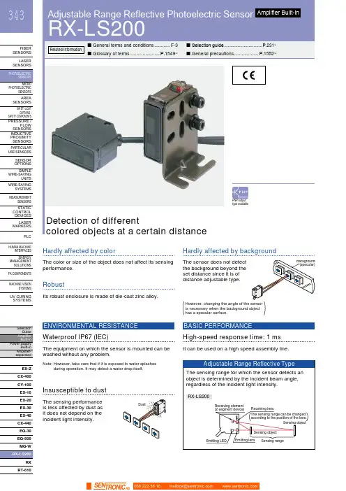
HUMAN MACHINEINTERFACESENERGYMANAGEMENTSOLUTIONSFA COMPONENTSMACHINE VISIONSYSTEMSUV CURINGSYSTEMSCX-400CY-100EX-10EX-20EX-30EX-40CX-440EQ-30EQ-500MQ-WRXRT-610Hardly affected by colorThe color or size of the object does not affect its sensingperformance.Hardly affected by backgroundThe sensor does not detectthe background beyond theset distance since it is ofdistance adjustable type.RobustIts robust enclosure is made of die-cast zinc alloy.High-speed response time: 1 msIt can be used on a high speed assembly line.BASIC PERFORMANCEWaterproof IP67 (IEC)The equipment on which the sensor is mounted can bewashed without any problem.ENVIRONMENTAL RESISTANCENote: H owever, take care that if it is exposed to water splashesduring operation. It may detect a water drop itself.Insusceptible to dustThe sensing performanceis less affected by dust asit does not depend on theincident light intensity.has a specular surface.Adjustable Range Reflective Photoelectric SensorRX-LS200344FIBER SENSORSLASER SENSORS PHOTO-ELECTRIC SENSORS AREA SENSORS SAFETY LIGHT CURTAINS /SAFETY COMPONENTS PRESSURE / FLOW SENSORS INDUCTIVE PROXIMITY SENSORS PARTICULAR USE SENSORS SENSOR OPTIONS SIMPLE WIRE-SAVING UNITS WIRE-SAVING SYSTEMSMEASURE-MENT SENSORS STATIC CONTROL DEVICES LASER MARKERS PLC HUMAN MACHINE INTERFACES ENERGY MANAGEMENT SOLUTIONS FACOMPONENTS MACHINE VISION SYSTEMSUVCURINGSYSTEMSEX-Z CX-400CY-100EX-10 EX-20EX-30EX-40CX-440EQ-30EQ-500RX RT-6105 m cable length type5 m 16.404 ft cable length type (standard: 3 m 9.843 ft ) is also available for NPN output type.Model No.: RX-LS200-C5Accessory• MS-RX-1 (Sensor mounting bracket)Narrow-view slit mask• OS-RXL-□Protective tubeTwo M4 (length 16 mm 0.630 in )hexagon-socket-head bolts are attached.056 222 38 18*********************SEN TRONIC AG345Adjustable Range Reflective Photoelectric Sensor RX-LS200FIBERSENSORSLASERSENSORSPHOTO-ELECTRICSENSORSAREASENSORSSAFETY LIGHTCURTAINS /SAFETYCOMPONENTSPRESSURE /FLOWSENSORSINDUCTIVEPROXIMITYSENSORSPARTICULARUSESENSORSSENSOROPTIONSSIMPLEWIRE-SAVINGUNITSWIRE-SAVINGSYSTEMSMEASURE-MENTSENSORSSTATICCONTROLDEVICESLASERMARKERSPLCHUMANMACHINEINTERFACESENERGYMANAGEMENTSOLUTIONSFACOMPONENTSMACHINEVISIONSYSTEMSUVCURINGSYSTEMSEX-ZCX-400CY-100EX-10EX-20EX-30EX-40CX-440EQ-30EQ-500RXRT-610I/O circuit diagram Wiring diagramSymbols … D : Reverse supply polarity protection diodeZ D : Surge absorption zener diodeTr : NPN output transistor±10 %RX-LS200NPN output type 056 222 38 18*********************SEN TRONICAGAdjustable Range Reflective Photoelectric SensorRX-LS200346FIBER SENSORS LASER SENSORS PHOTO-ELECTRIC SENSORSAREA SENSORS SAFETY LIGHT CURTAINS /SAFETY COMPONENTS PRESSURE / FLOW SENSORS INDUCTIVE PROXIMITY SENSORS PARTICULAR USE SENSORS SENSOR OPTIONS SIMPLE WIRE-SAVING UNITS WIRE-SAVING SYSTEMSMEASURE-MENT SENSORS STATIC CONTROL DEVICES LASER MARKERS PLC HUMAN MACHINE INTERFACES ENERGY MANAGEMENT SOLUTIONS FACOMPONENTS MACHINE VISION SYSTEMS UVCURINGSYSTEMSEX-Z CX-400CY-100EX-10EX-20EX-30EX-40CX-440EQ-30EQ-500RX RT-610I/O circuit diagramWiring diagramNote: T he output does not incorporate a short-circuit protection circuit.Do not connect it directly to a power supply or a capacitive load.Symbols … D : Reverse supply polarity protection diodeZ D : Surge absorption zener diode Tr : PNP output transistorto 24 V DCSensing fields• Setting distance: 200 mm 7.874 in (Horizontal)• Setting distance: 200 mm 7.874 in (Vertical)• Setting distance: 150 mm 5.906 in (Horizontal)• Setting distance: 150 mm 5.906 in (Vertical)• Setting distance: 150 mm 5.906 in with slit mask (Vertical)• Setting distance: 150 mm 5.906 in with slit mask(Horizontal)0.3940.394Left Center in )S e t t i n g d i s t a n c e L (m m i n Up Center Operating point ℓ (mm in )0.3940.394S e t t i n g d i s t a n c e L (m m in Left Center in)0.1570.157S e t t i n g d i s t a n c e L (m mi nUp Center in )0.1570.157S e t t i n g d i s t a n c e L(m m i nLeft Center Operating point ℓ (mm in )0.1570.157S e t t i n g d i s t a n c e L (m m i nUp Operating point ℓ (mm in )0.1570.157S e t t i n g d i s t a n c e L (m m i nCorrelation between sensing object size and sensing range0.787 1.575 2.362 3.1503.937 in , 7.874 in , each, with white non-glossy 1.969 × 1.969 in ).side length a (mm in )S e n s i n g r a n g e L (m m i n D i s t a n c e L (m m i n RX-LS200-P PNP output type056 222 38 18*********************SEN TRONIC AG347Adjustable Range Reflective Photoelectric Sensor RX-LS200FIBERSENSORSLASERSENSORSPHOTO-ELECTRICSENSORSAREASENSORSSAFETY LIGHTCURTAINS /SAFETYCOMPONENTSPRESSURE /FLOWSENSORSINDUCTIVEPROXIMITYSENSORSPARTICULARUSESENSORSSENSOROPTIONSSIMPLEWIRE-SAVINGUNITSWIRE-SAVINGSYSTEMSMEASURE-MENTSENSORSSTATICCONTROLDEVICESLASERMARKERSPLCHUMANMACHINEINTERFACESENERGYMANAGEMENTSOLUTIONSFACOMPONENTSMACHINEVISIONSYSTEMSUVCURINGSYSTEMSEX-ZCX-400CY-100EX-10EX-20EX-30EX-40CX-440EQ-30EQ-500RXRT-610Correlation between material (50 × 50 mm 1.969 × 1.969 in) and sensing range200 mm 7.874 in100 mm 3.937 in50 mm 1.969 inWhitenon-glossypaperPlywoodCardboardCeramiccircuitboardGraynon-glossypaper(Lightness:3)BlackrubbeMirrorThese bars indicate the sensing rangewith respective objects when thedistance adjuster is set at the sensingrange of 200 mm 7.874 in, 100 mm3.937 in and 50 mm 1.969 in long,each, with white non-glossy paper.(GreenmaskedsurfaceGlassepoxyprintedcircuitboardSensingrangeL(mminWiring• The output of RX-LS200-P does not incorporate a short-circuit protection circuit. Do not connect it directly to apower supply or a capacitive load.Others• Do not use during the initial transient time (50 ms) afterthe power supply is switched on.Mounting• The tightening torque should be 1.17 N·m or less.• Care must be taken regarding the sensor mountingdirection with respect to the object’s direction of movement.Do not make the sensordetect an object in thisdirection because it maycause unstable operation.Sensing object Sensing object Sensing objectintersection of the “ ”mark on the lens faceand the “ ” line.• When detecting a specular object (aluminum or copperfoil) or an object having a glossy surface or coating,please take care that there are cases when the objectmay not be detected due to a small change in angle,wrinkles on the object surface, etc.• When a specular body is present below the sensor, usethe sensor by tilting it slightly upwards to avoid wrongoperation.Use conditions to comply with CE Marking• Following work must be done in case of using thisproduct as a CE marking (European standard EMCDirective) conforming product.Ensure that the shield is connected to 0 V or the actualground.• In case of connecting a sensor to power supply 0 V by usinga shield (piping, etc.)• In case of grounding by using a shield (piping, etc.)Note: The shield (piping, etc.) must be insulated.• If a specular body is present in the background, wrongoperation may be caused due to a small change in theangle of the background body. In that case, install thesensor at an inclination and confirm the operation withthe actual sensing object.• Do not install the sensor at a distance of less than 50 mm1.969 in from the object because the sensing is unstablein this range.Correct Correct Incorrect056 222 38 18*********************SEN TRONICAGAdjustable Range Reflective Photoelectric SensorRX-LS200348FIBER SENSORS LASER SENSORS PHOTO-ELECTRIC SENSORS AREA SENSORSSAFETY LIGHT CURTAINS /SAFETY COMPONENTS PRESSURE / FLOW SENSORSINDUCTIVE PROXIMITY SENSORS PARTICULAR USE SENSORSSENSOR OPTIONS SIMPLE WIRE-SAVING UNITS WIRE-SAVING SYSTEMSMEASURE-MENT SENSORS STATIC CONTROL DEVICES LASER MARKERS PLC HUMAN MACHINE INTERFACES ENERGY MANAGEMENT SOLUTIONS FACOMPONENTS MACHINE VISION SYSTEMSUVCURINGSYSTEMSEX-Z CX-400CY-100EX-10 EX-20EX-30EX-40CX-440EQ-30EQ-500RX RT-610Distance adjustmentSensorRX-LS200 RX-LS200-PProtective tube (Optional)PT-RX500 PT-RX1000MS-RX-1Sensor mounting bracket (Accessory)Assembly dimensions• Follow only steps 1 and 2 respectively. Since the sensing point may change depending on the sensing object, be sure to check the operation with the actual sensing object.<When a sensing object is approaching / moving away from the sensor><When a sensing object moves horizontally to the sensor>) hexagon-socket-AdjustersAdjusting procedure056 222 38 18*********************SEN TRONIC AG。


Schneider Baoguang关于施耐德宝光施耐德(陕西)宝光电器有限公司(简称SSBEA或施耐德宝光)是施耐德电气有限公司与陕西宝光集团有限公司共同组建的一家专业从事中、系统及相关产品研发、生产和销售的中外合资企业。
高新科技园区。
在世界五百强企业与中国中压电器龙头企业的通力合作下,作为国内中压行业著名的“宝光”品牌真空断路器的唯一合法生产商,施耐德宝光秉承精益生产科学理念,凭借品质过硬、安全可靠的全系列高品质产品和覆盖用户全生命周期的完善服务,帮助用户实现卓越的生产运营绩效和市场竞争力,用品质的“不妥协”实现可持续发展之道。
我们致力于将施耐德宝光打造成为中国卓越和高效的中压断路器和系统的制造平台,依托自身的专业优势,为广大用户和合作伙伴提供领先的总成本和长期全面的安心保障。
目录V5系列新一代微机保护测控装置 (1)产品概述 (1)产品特点 (2)型号及功能说明 (3)保护功能 (4)测控功能 (6)技术参数 (7)典型接线图 (8)外形尺寸及面板开孔尺寸 (11)V5订货选型表 (12)V3系列微机保护测控装置 (13)产品概述 (13)产品特点 (14)型号及功能说明 (15)保护功能 (16)测控功能 (17)技术参数 (18)典型接线图 (19)外形尺寸及面板开孔尺寸 (21)V3订货选型表 (22)V3U微机综合保护装置 (23)产品概述 (23)型号及功能说明 (24)保护功能 (25)测控功能 (26)技术参数 (27)外形尺寸图/典型接线图 (28)后台系统 (29)系统总体结构 (30)V5系列新一代微机保护测控装置是一种用于测量、控制、保护、通讯一体化的智能设备,产品主要用于工业及能源领域对线路、变压器、电动机及电容器的保护测控。
此产品外观时尚、结构精巧、大屏幕液晶显示,图形化中文菜单,四位方向导航盘,操作快捷方便。
内部基于SOC芯片软件方案,32位处理器,并根据硬件进行深度改良优化的嵌入式操作系统,使CPU运行效率更高。

部分产品快速选型手册 2011/2012 海格电气公司为了给中国市场广大用户提供更好的产品服务,我们现将原在公司内部物流管理层所用的部分产品物流编号(物流型号,开放给广大用户使用,并据此重新编制了对应的空气断路器和塑壳断路器的“快速选型手册”。
当用户使用本手册时,需要参考以前刊印的海格产品选型手册相关内容。
我们保证了原“产品样本型号”与内部的“物流型号”在对同一特定产品的唯一性。
在工程设计中,无论使用“产品样本型号”还是“物流型号” 都可由用户自愿选择。
当然使用“物流型号”会给用户带来某些方面的便利。
这也是我们公布“物流型号”的初衷。
我们声明:海格电气公司保留今后对产品型号解释权。
如有疑问欢迎咨询海格电气公司市场部及销售人员。
非常感谢广大客户长期以来对海格电气公司的支持和信赖,我们承诺:继续做好对中国市场广大客户的产品服务。
谨礼!目录 ACB产品物流型号命名方法 HDC系列MCCB物流型号命名方法 HBC系列MCCB物流型号命名方法 HVN系列ELCB物流型号命名方法MSG选型对照表(ACB/MCCB 1 2 3 4 5 25 27 29 附录:基本术语常用公式2011/2012年年历分断能力字母代码说明样本型号分断能力的字母表示 H N E S P ACB 55KA 65KA 80KA 物流型号分断能力的字母表示 HDC HBC ELCB 25KA35KA 35KA 50KA 50KA 50KA 80KA HDC HBC ELCB ACB 25KA H 55KA 35KA50KA F 50KA 50KA N 65KA 80KA E 80KA S 80KA 100KA P 100KA 1 ACB产品物流型号命名方法 HW 附件 N 1000A D / 3P / LSI / HW:海格主开关系列空气断路器分断能力 N:65kA(框架I、II) S:80kA (框架II、III) P:100kA(框架III)控制器 LS-两段式 LSLCD两段式,液晶屏 LSI-三段式 LSILCD-三段式.液晶屏 LSIG-四段式 LSIGLCD-四段式,液晶屏可选附件 MX: 分励继电器 (电压可选择 UV: 欠压继电器 (瞬时 (电压可选择 UV-D: 欠压继电器 (延时 (电压可选择 CF: 故障指示触点MH: 储能电机 (电压可选择 PF: 准备合闸触点 BL: OFF锁代号 (详见样本安装形式F-固定式 D-抽出式标配附件 4NO+4NC辅助触点分励继电器(电压可选择合闸继电器(电压可选择储能电机 (电压可选择框架II: 2000A 2500A 额定电流(A 框架I: 630A 800A 1000A 1250A 1600A 框架III:3200A 4000A 极数 3P(可以缺省 4P 注: 附件需要标出电压时230Vac可缺省举例:HWN1600A/ D/3P/ LSI /UV+CF 说明:In=1600A,分断能力65kA,抽出式,3P,三段式保护控制器,带故障指示触点,欠压继电器。

SELECTION GUIDE According to EN 954-1** The given information is indicative and synthetic; it is compulsory to refer to the complete EN 954 standard for a correct risk and safety type evaluation.TYPE2TYPE41515UNSHIELDEDCABLESSHIELDED CABLESAPPLICATIONSO P E R A T I N G P R O T E C T I O N P O I N TACCESSORIESC O N N E C T O R C A B L E SS E 2-335S F 2-330POWER SUPPLY 24 Vdc 24 Vdc RESOLUTION 35 mm 30 mm OPERATING RANGE 0.2 ... 15 m 0.2 ... 15 m CONTROLLED HEIGHT 150 ... 1650 mm 150 ... 1500 mm RESPONSE TIME 15 ... 32 ms 24 ms max.OUTPUT 2 transistor PNP2 transistor PNPCONNECTION Rx:M12 8-poles; Tx:M12 4-polesRx:M12 5-poles; Tx:M12 4-polesDIMENSIONS 35 x 40 mm31 x 32 mm DEVICE FUNCTIONSTestTestManual/auto reset selection Manual reset Total/partial Muting selection Automatic resetOverrideCERTIFICATIONSAutomatic packaging machinesAutomated assembly lines Automatic working machines Automatic machines for packing and packaging Automatic warehousing and materials handling Automated assembly lines (pick and place)Textile, ceramic, wood and leather industryAccording to IEC 61496-1/ IEC 61496-2C V s e r i e sC S s e r i e sM12 axial and radial connector cables with 3, 4, 8 poles Cable lengths: 3, 5, 10, 15, 25 m Cable material: PVCThe use of shielded cables is compulsory for the safety devices of the SE2and SE4 series, suggested for the Sx -SS T2/ST4M12 axial and radial connector cables with 3, 4, 5 polesCable lengths: 3, 5, 7, 10 m Cable material: PVCM12 4-poles non-cabled connectors are availableAPPLICATIONSO P ER AT IN G P R O T E C T I O N P O I N TS E 4-330S E 4-335POWER SUPPLY24 Vdc 24 Vdc 24 Vdc 24 Vdc RESOLUTION 14 mm 20 mm 30 mm 35 mm OPERATING RANGE 0.2 ... 6 m 0.2 ... 6 m 0.2 ... 15 m 0.2 ... 15 m CONTROLLED HEIGHT 150 ... 900 mm 150 ... 1650 mm 150 ... 1650 mm 150 ... 1650 mm RESPONSE TIME 18 ... 39 ms 16 ... 39 ms 15 ... 32 ms 15 ... 32 ms OUTPUT 2 transistor PNP2 transistor PNP2 transistor PNP2 transistor PNPCONNECTION Rx:M12 8-poles; Tx:M12 4-polesRx:M12 8-poles; Tx:M12 4-polesRx:M12 8-poles; Tx:M12 4-polesRx:M12 8-poles; Tx:M12 4-polesDIMENSIONS 35 x 40 mm 35 x 40 mm 35 x 40 mm 35 x 40 mm DEVICE FUNCTIONSTestTestTestTestManual/auto reset selection Manual/auto reset selection Manual/auto reset selection Manual/auto reset selection Total/partial Muting selectionTotal/partial Muting selectionTotal/partial Muting selectionTotal/partial Muting selectionOverrideOverride Override OverrideCERTIFICATIONSOTHER FUNCTIONS S E 4-114S E 4-220Benders and cuttersMetal, plastic and leather working machinesPresses and punching machinesMetal forming, milling and drilling machinesAccording to IEC 61496-1/IEC 61496-2Presses and punching machinesBenders and cutters Metal working machines COLUMN AND FLOOR STANDSACCESSORIESC O L U M N A ND F L O O R S T A N D S / P R O TE C T I V E S T A N D SPROTECTIVE STANDSS E -S S s e r i e sS E -P P s e r i e sTo be used with the SE2, SE4, SF2safety light curtains series and SE -DD M deviating mirror series Available in different heights:800, 1000 and 1200 mm with 30 x 30 mm profile dimensions1500 and 1800 mm with 45 x 45 mm profile dimensionsGround fixing plate dimensions: 240 x 240 mmTo be used with the SE2, SE4and SF2 safety light curtains series Available in different heights ranging from 273 mm to 1743 mmPRESENCE CONTROL PROTECTION: TYPE 2APPLICATIONSPR ES EN C E C O N T R O L P R O T E C T I O NS F 2-550S F 2-990POWER SUPPLY 24 Vdc 24 Vdc RESOLUTION 50 mm 90 mm OPERATING RANGE 0.2 ... 15 m 0.2 ... 15 m CONTROLLED HEIGHT 300 ... 1500 mm 300 ... 1500 mm RESPONSE TIME 24 ms max.24 ms max.OUTPUT 2 transistor PNP2 transistor PNPCONNECTION Rx:M12 5-poles; Tx:M12 4-polesRx:M12 5-poles; Tx:M12 4-polesDIMENSIONS 31 x 32 mm 31 x 32 mm DEVICE FUNCTIONS TestTestAutomatic resetAutomatic resetCERTIFICATIONSStorage and stacking areasWorking areas Robot areas Robot areas Transfer areas Palletising areasStorage and stacking areasAccording to IEC 61496-1/ IEC 61496-2(pending)(pending)ACCESSORIESF I X I NG B R A C K E T S / S A F E T Y R E L A Y SFIXING BRACKETSSAFETY RELAYSS T s e r i e sS E -S S R 2 s e r i e sThe fixing brackets are supplied together with the safety light curtains of the SE2, SE4 and SF2 seriesStandard fixing brackets (4 pcs kit) are available for the SE2and SE4safety light curtains, as well as orientable, anti-vibration supports and anti-scratch fixing brackets for the SF2 seriesT ype 4 safety relays - safety contacts: 3 NO 1 NCT o be used with the SE2, SE4and SF2safety light curtain seriesPRELIMINARYPRELIMINARYAPPLICATIONSA C C E S S P R O T E C T I O NSB -B B WS-T T 2+Sx -SS T2POWER SUPPLY 24 Vdc24 Vdc N° BEAMS2-3-4up to 2OPERATING RANGE 0.5 ... 50 mup to 50 m CONTROLLED HEIGHT500-800-900-1200 mm 500 mm RESPONSE TIME 14 ms22 ms max.OUTPUT 2 transistor PNP2 relayCONNECTION Rx:M12 8-poles; Tx:M12 4-polesDIMENSIONS 35 x 40 mmDEVICE FUNCTIONSTestTestManual/auto reset selection Manual resetTotal/partial Muting selection OverrideS E 2-P PCERTIFICATIONSAccording to IEC 61496-1/ IEC 61496-2Automatic warehousesRobots Transfer areasPalletisers / depalletisers Automatic warehousesAccess control, working areas and robotsConveyorsSAFETY SENSORS3-pole shielded cable S5/S10-ST2M12 connector – S5/S10/S30-ST2Terminal block – S30-ST2SB-BWS-T2 control unitS5-ST2 M18 plastic safety sensors S10-ST2 M18 metal safety sensors S30-ST2 maxi safety sensorsACCESSORIESD E V I A T I N G M I R R O R S / L A S E R P O I N T E RDEVIATING MIRRORSLASER POINTERS E -D D M s e r i e sS E -L L P s e r i e sT o be used with safety light curtains of the SE2, SE4, SF2series and Sx -S S T2/ST4monobeam safety photosensor seriesAvailable in different heights ranging from 150 mm to 1800 mm Deviating mirrors dimensions: 124 mm width, 6 mm depthTo be used with SE2and SE4 safety light curtain seriesACCESSORIESMUTIN G D E V I C E S /T E S T P I E C E S APPLICATIONSA C C E S S P R O T E C T I O NS E 4-P PSB -B B WS -T T 4+Sx -S S T4POWER SUPPLY 24 Vdc 24 Vdc 24 Vdc N° BEAMS2-3-42-3-42-3-4OPERATING RANGE 0.5 ... 25 m4 ... 50 mup to 50 m CONTROLLED HEIGHT 500-800-900-1200 mm 500-800-900-1200 mm RESPONSE TIME 14 ms14 ms32 ms max.OUTPUT 2 transistor PNP2 transistor PNP2 relayCONNECTION Rx:M12 8-poles; Tx:M12 4-polesRx:M12 8-poles; Tx:M12 4-polesDIMENSIONS 35 x 40 mm 35 x 40 mm DEVICE FUNCTIONSTestTestTestManual/auto reset selection Manual/auto reset selection Manual/auto reset selection Total/partial Muting selection Total/partial Muting selection Total/partial Muting selection OverrideOverrideDouble Muting/OverrideS E 4-Q QCERTIFICATIONSAccording to IEC 61496-1/ IEC 61496-2Assembly robotised linesPalletisers Conveyors Palletisers / depalletisers Automatic warehousesAccess control, working areas and robotsConveyorsSAFETY SENSORS3-pole shielded cable S5/S10-ST4M12 connector – S5/S10/S30/SL5-ST4T erminal block – S30-ST4SB-BWS-T4 control unitS5-ST4 M18 plastic safety sensors S10-ST4 M18 metal safety sensorsSL5-ST4 laser M18plastic safety sensors S30-ST4 maxi safety sensorsMUTING DEVICESTEST PIECESL M S s e r i e sMuting lamps: standard, tower modular, with horizontal and vertical mountingMuting sensors: DATASENSOR non-safety sensors can be used (refer to relative documentation)T P s e r i e sVersions with 14, 20, 30 and 35 mm diameterOTHER FUNCTIONSDATASENSOR SpA is the Italian leading company in the production and sales of optoelectronic devices for detection, safety, measurement and inspection for industrial automation. The range includes complementary products, such as temperature controllers and ultrasonic sensors. The DATASENSOR worldwide presence is guaranteed by the subsidiaries in France, Germany, Spain and UK, as well as a widespread network of local distributors, including selected Qualified Automation Partners (QAPs). Thanks to its unique technology of the product and production process, DATASENSOR can boast an active partnership with the main companies operating in the world of automation.T h e w o r l d w i d e d i s t r i b u t i o n n e t w o r k i s o n -l i n e :w w w .d a t a s e n s o r .c omDATASENSOR SpAvia Lavino 265, 40050 Monte San Pietro, BO - Italy Tel. +39 051/6765611 • Fax +39 051/6759324 •e-mail:*******************DATASENSOR FRANCE Tel. +33 (0)4/72476180Fax +33 (0)4/72470721 e-mail:******************DATASENSOR GmbH Tel. +49 (0)8104/89060Fax +49 (0)8104/890699e-mail:******************。
高压避雷器概述:高压避雷器是电力系统各类电气设备(变压器、电容器、发电机、电动机、PT、CT、断路器、接触器等)绝缘配合的基础,由避雷器的保护性能确定电力系统所有电气设备的内外绝缘指标(短时工频耐压、雷电冲击耐压和操作冲击耐压等)。
金属氧化物避雷器是20世界八十年代由美、日等国开始在国际上普及推广的新一代避雷器,是常规避雷器最先进的产品。
我国八十年代中期全面引进该项技术后,通过多年实践消化,目前各专业避雷器厂的交流避雷器性能与美、日、西欧等国的最先进产品差距并不大,真正达到了国标全部要求的产品也可以满足国标IEC标准的全部要求。
该产品核心工作元件采用以氧化锌为主的多元金属氧化物粉末烧制,具有优异的非线性状一安特性,徒波响应快,通流容量大。
有间隙产品采用自吹间隙,带均压照射结构,降低了放电的分散性,冲击系数小。
复合绝缘外套的采用,顺应了国际电力产品小型化,安全化,免维护的发展趋势。
高分子有机复合材料与传统的陶瓷和玻璃等无机材料相比,具有体积小、重量轻、耐污秽免清扫、防爆防震的优点。
是集成化、模块化的中高压输变电成套设备中首选的防雷元件。
高压系列避雷器产型号说明和用途及执行标准:本产品使用于交流220kV及以下发电、输电、变电、配电系统,用于将雷电和系统内部作操过电压的幅值限制到规定的水平,是整个系统绝缘配合的基础设备。
同时,本产品不能用于限制谐振过电压,系统消谐需要采用其它方式。
本产品型号按JB/T8459-1996《避雷器产品型号编制方式》规定进行编制,无间隙产品执行GB11032-2000《交流无间隙金属氧化物避雷器》产品执行JB/T9672-1999《有串联间隙金属氧化物避雷器》标准。
对以上标准中未明确定义的重要参数及配电方式,接DL/T620-1997《交流电气装置的过电压保护和绝缘配合》的要求修正执行。
高压避雷器(配电型避雷器):■用于保护相应电压等级的电力主变、开关柜、箱式变、电力电缆出线头、柱上开关等配电设备免受大气过压及操作过电压的危险高压避雷器(电站型避雷器):■用于保护发电厂、变电站的交流电气设备免受大气过电压和操作电压的损坏高压避雷器(低压型避雷器):■电柜、开关柜及控制柜中,保护柜上的电器设备免受过电压的危害高压避雷器(保护电容器组型避雷器):■用于限制真空开关及少油开关在操作时对并联电容器组产生的过电压危害,保护电容组免受损害并吸收过电压的能量高压避雷器(电气化铁道型):■用于保护电气化铁道的各种电气设备、接触网、电力机车免受大气过电压和操作电压的损坏高压避雷器(变压器中性点型避雷器):■用于保护相应电压等级的变压器中性点免受大气过电压和操作过电压的损坏高压避雷器(线路无间隙型电气参数表):高压避雷器(电机型避雷器):■用于限制真空开关或少油开关切换旋转电机时产生的过电压,保护旋转电机免受操作过电压损坏。
GeneralThe following questionnaires are used to select sensors according to the client's requirements.The characteristics shown in the catalogue are given with respect to a defined environment (worst case conditions).The technical requirements will not always reach these extreme limits, and it is possible, following confirmation by us, to propose higher maximum electrical or thermal values to those published, thanks to a knowledge and detailed analysis of the sensor operating environment.A technical relationship between the client and ABB will allow the proposal of the best selection of sensors, equally from the viewpoint of performance and economy.Two principal areas are considered in the selection of a sensor:–the electrical aspect–the thermal aspectThe sensor performance is based on a combination of electrical and thermal conditions; any values other than those indicated in this catalogue cannot be guaranteed unless validated by us. The information below is only valid for sensors using closed loop Hall effect technology.Contact your local supplier for other technologies.Profile missionDue to the design of converters with integrate more power with less volume, sensors are very constraint; leading to reduce their life time. As a matter of fact, even though the application main conditions are well within the sensors characteristics, these conditions have an impact on the sensor life time.The main general characteristics that involves the sensors life time are the following:–the ambient temperature above 40 °C. It is usually said that every additional 10 °C, the life time is reduced by a factor of 2. Of course, this value is a theoretical value and has to be defined in line with the concerned project.–the ambient temperature variations also impact the sensor life time. Even small variations (like 10 °C) can change the life time of the sensor especially on the electronic part.–the way the sensors are used also impact its duration (numbers of ON/OFF per day, average current or voltage value, powersupply value, load resistor value, vibrations levels…)The above general impacting conditions are well defined in standards like IEC 62380, UTE C 80-810 and must be consider during any new converter design.ABB can provide theoretical reliability calculation based on specific profile mission of your projects.Electrical characteristicsThe electrical characteristics values mentioned in this catalogue are given for a particular sensor operating point. These values may vary, according to the specific technical requirement, in the following way:–The primary thermal current (voltage) (I PN or U PN) may be increased if:-t he maximum operating temperature is lower than thevalue shown in the technical data sheet-the sensor supply voltage (V A) is reduced-the load resistance value (R M) is increased–The maximum current (voltage) measurable by the sensor may be increased if:-the maximum operating temperature is lower than thevalue shown in the technical data sheet-the sensor supply voltage (V A) is increased-the secondary winding resistance value (R S) is reduced(e.g. by using a lower transformation ratio)-the load resistance value (R M) is reducedThermal characteristicsThe operating temperature values mentioned in this catalogue are given for a particular sensor operating point. These values may vary, according to the specific technical requirement, in the following way:–The maximum operating temperature may be increased if: -the primary thermal current (voltage) (I PN or U PN) is reduced -the sensor supply voltage (V A) is reduced-the load resistance value (R M) is increasedPS: The minimum operating temperature cannot be lower than that shown in the technical data sheet as this is fixed by the lower temperature limit of the components used in the sensor.74S21Application1. Application :–Variable speed drive ................................................................ –UPS ....................................................................................... –Wind generator ....................................................................... –Active harmonic filter ............................................................... –Welding machines ................................................................... –Solar ...................................................................................... –Other (description) ......................................................................2. Quantity per year: ...........................................................................Mechanical characteristics1. Sensor fixing:–By soldering to the PCB .......................................................... –By the enclosure ..................................................................... –By the primary conductor ........................................................ 2. Primary conductor:–Cable diameter ................................................................... (mm) –Cable connection size ......................................................... (mm) –Bar size .............................................................................. (mm)3. Secondary connection:–By connector .......................................................................... –By cable without connector ..................................................... –Other ......................................................................................Sensor environmental conditions1. Minimum operating temperature ................................................ (°C)2. Maximum operating temperature ............................................... (°C)3. Presence of strong electromagnetic fields ....................................4. Max. continuous primary conductor voltage ................................ (V)5. Main reference standards ................................................................Electrical characteristics1. Nominal current (I PN ) ......................................................... (A r.m.s.)2. Current type (if possible, show current profile on graph):–Direct ..................................................................................... –Alternating .............................................................................. 3. Bandwidth to be measured ...................................................... (Hz)4. Current measuring range:–Minimum current .................................................................... (A) –Maximum current ................................................................... (A) –Duration (of max. current) .................................................... (sec) –Repetition (of max. current) ......................................................... –Measuring voltage (on R M ) at max current .............................. (V)5. Overload current (not measurable):–Not measurable overload current ........................................... (A) –Duration.............................................................................. (sec) –Repetition ...................................................................................6. Sensor supply voltage:–Bipolar supply voltage .......................................................... (±V) –Unipolar supply voltage .......................................... (0 +V or 0 -V)7. Output current–Secondary current at nominal current I PN ............................. (mA) 8. Current output (NCS range only)–Secondary current at maximum current I PMAX ....................... (mA)9. Voltage output–Secondary voltage at nominal current I PN ............................... (V)10. Voltage output (NCS range only)–Secondary voltage at maximum current I PMAX (V)Company:Address:Tel:Name:Fax:Email:Other requirements (description)74S 0201Company:Address:Tel:Name:Fax:Email:Other requirements (description)Application1. Project name ...................................................................................2. Application:Rolling stock:–Power converter ..................................................................... –Auxiliary converter ................................................................... –Other ......................................................................................Short or long distance train:–Power converter ..................................................................... –Auxiliary converter ...................................................................Metro or tramway:–Power converter ..................................................................... –Auxiliary converter ................................................................... Fixed installation (e.g. substation)..................................................... 3. Quantity per year: ............................................................................4. Total quantity for the project.............................................................Mechanical characteristics1. Sensor fixing:–By the enclosure ..................................................................... –By the primary conductor ........................................................ 2. Primary conductor:–Cable diameter ................................................................... (mm) –Bar size .............................................................................. (mm) 3. Secondary connection:–Screw or Faston...................................................................... –By connector .......................................................................... –By shielded cable .................................................................... –Other ...................................................................................... Electrical characteristics1. Nominal current (I PN ) .......................................................... (A r.m.s.)2. C urrent type (if possible, show current profile on graph):–Direct ..................................................................................... –Alternating .............................................................................. 3. Bandwidth to be measured ....................................................... (Hz)4. Current measuring range:–Minimum current .................................................................... (A) –Maximum current ................................................................... (A) –Duration (of max. current) .................................................... (sec) –Repetition (of max. current) ......................................................... –Measuring voltage (on R M ) at max current .............................. (V)5. Overload current (not measurable):–Not measurable overload current ............................................(A) –Duration.............................................................................. (sec) –Repetition ...................................................................................6. Sensor supply voltage:–Bipolar supply voltage .......................................................... (±V) –Unipolar supply voltage .......................................... (0 +V or 0 -V)7. Output current–Secondary current at nominal current I PN ............................. (mA) 8. Current output (NCS125 & NCS165 only for fixed installations)–Secondary current at maximum current I PMAX ....................... (mA)9. Voltage output (NCS125 & NCS165 only for fixed installations)–Secondary voltage at nominal current I PN ............................... (V)10. Voltage output (NCS125 & NCS165 only for fixed installations)–Secondary voltage at maximum current I PMAX (V)Sensor environmental conditions1. Minimum operating temperature ................................................ (°C)2. Maximum operating temperature ............................................... (°C)3. Average nominal operating temperature ......................................(°C)4. Maximum continuous primary conductor voltage ..........................(V)5. Main reference standards ................................................................74S 0201Company:Address:Tel:Name:Fax:Email:Other requirements (description)Application1. Project name ...................................................................................2. Application:Short or long distance train:–Power converter ..................................................................... –Auxiliary converter ...................................................................Metro or tramway:–Power converter ..................................................................... –Auxiliary converter ...................................................................Fixed installation (e.g. substation) ................................................ 3. Quantity per year: ............................................................................4. Total quantity for the project.............................................................Mechanical characteristics1. Primary connection:–By screw ................................................................................ –Other ...................................................................................... 2. Secondary connection:–Screw or Faston...................................................................... –By connector .......................................................................... –Other ...................................................................................... Electrical characteristics1. Nominal voltage (U PN ) ........................................................ (V r.m.s.)2. Voltage type (if possible, show voltage profile on graph):–Direct ..................................................................................... –Alternating .............................................................................. 3. Bandwidth to be measured ...................................................... (Hz)4. Voltage measuring range:–Minimum voltage .................................................................... (V) –Maximum voltage ................................................................... (V) –Duration (at max. voltage) .................................................... (sec) –Repetition (at max. voltage) ......................................................... –Measuring voltage (on R M ) at max voltage ............................... (V)5. Overload voltage (not measurable):–Not measurable overload voltage ............................................ (V) –Duration.............................................................................. (sec) –Repetition ................................................................................... –Category (from OV1 to OV3) ........................................................6. Sensor supply voltage:–Bipolar supply voltage .......................................................... (±V) –Unipolar supply voltage .......................................... (0 +V or 0 -V)7. Output current–Secondary current at nominal voltage U PN ............................ (mA)Sensor environmental conditions1. Minimum operating temperature ................................................ (°C)2. Maximum operating temperature ............................................... (°C)3. Average nominal operating temperature .....................................(°C)4. Main reference standards ................................................................74S 0201Company:Address:Tel:Name:Fax:Email:Other requirements (description)Application1. Project name ...................................................................................2. Application:Short or long distance train:–Power converter ..................................................................... –Auxiliary converter ...................................................................Metro or tramway:–Power converter ..................................................................... –Auxiliary converter ...................................................................Fixed equipment (e.g. substation) ................................................ 3. Quantity per year: ...........................................................................4. Total quantity for the project.............................................................Electrical characteristics1. Nominal voltage (U PN ) ............................................................ (V DC)2. Maximum voltage long duration: 5 min (U MAX2) ........................ (V DC)3. Maximum voltage overload: 20 ms (U MAX3) .............................. (V DC)4. Minimum voltage to be detected . (V)Sensor environmental conditions1. Minimum operating temperature ................................................ (°C)2. Maximum operating temperature ............................................... (°C)3. Average nominal operating temperature ..................................... (°C)4. Pollution degree ..............................................................................5. Over voltage category (from OV1 to OV3) .........................................6. Maximum ambient light level ......................................................(lux)7. Main reference standards ................................................................74S 0201。
电缆的选型与配线常用电工计算口诀第一章按功率计算电流的口诀之一1.用途:这是根据用电设备的功率(千瓦或千伏安)算出电流(安)的口诀。
电流的大小直接与功率有关,也与电压,相别,力率(又称功率因数)等有关。
一般有公式可供计算,由于工厂常用的都是380/220伏三相四线系统,因此,可以根据功率的大小直接算出电流。
2.口诀:低压380/220伏系统每kW的电流,安。
千瓦,电流,如何计算?电力加倍,电热加半。
单相千瓦,4.5安。
单相380,电流两安半。
3.说明:口诀是以380/220V三相四线系统中的三相设备为准,计算每千瓦的安数。
对于某些单相或电压不同的单相设备,其每千瓦的安数.口诀中另外作了说明。
①这两句口诀中,电力专指电动机。
在380V三相时(力率0.8左右),电动机每千瓦的电流约为2安,即将“千瓦数加一倍”(乘2)就是电流(安)。
这电流也称电动机的额定电流。
【例1】5.5kW电动机按“电力加倍”算得电流为11安。
【例2】40kW水泵电动机按“电力加倍”算得电流为80安。
电热是指用电阻加热的电阻炉等。
三相380伏的电热设备,每千瓦的电流为1.5安。
即将“千瓦数加一半”(乘1.5),就是电流(安)。
【例1】3千瓦电加热器按“电热加半”算得电流为4.5安。
【例2】15千瓦电阻炉按“电热加半”算得电流为23安。
这口诀并不专指电热,对于照明也适用。
虽然照明的灯泡是单相而不是三相,但对照明供电的三相四线干线仍属三相。
只要三相大体平衡也可以这样计算。
此外,以千伏安为单位的电器(如变压器或整流器)和以千乏为单位的移相电容器(提高力率用)也都适用。
即是说,这后半句虽然说的是电热,但包括所有以千伏安、千乏为单位的用电设备,以及以千瓦为单位的电热和照明设备。
【例1】12千瓦的三相(平衡时)照明干线按“电热加半”算得电流为18安。
【例2】30千伏安的整流器按“电热加半”算得电流为45安。
(指380伏三相交流侧)。
【例3】320千伏安的配电变压器按“电热加半”算得电流为480安(指380/220伏低压侧)。
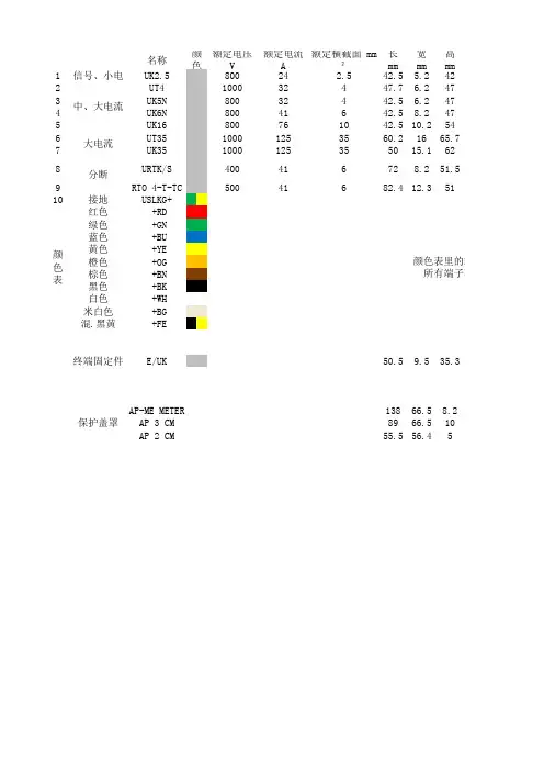
名称额定电压 V额定电流 A额定横截面 mm²长 mm 宽 mm 高 mm1信号、小电流UK2.580024 2.542.5 5.2422UT4100032447.7 6.2473UK5N 80032442.5 6.2474UK6N 80041642.58.2475UK16800761042.510.2546UT3510001253560.21665.77UK351000125355015.1628URTK/S 400416728.251.59RTO 4-T-TC 50041682.412.35110接地USLKG+红色 +RD 绿色 +GN 蓝色 +BU 黄色 +YE 橙色 +OG 棕色 +BN 黑色 +BK 白色 +WH 米白色 +BG 混.黑黄+FE终端固定件E/UK 50.59.535.3AP-ME METER 13866.58.2AP 3 CM 8966.510AP 2 CM 55.556.45颜色表颜色表里的端子所有端子不一定有颜色表里分断大电流保护盖罩中、大电流颜色端板隔板桥接件 螺桥接件 插标识条D-UK2.5ATP-UK FBRI 10-5N EBL 10-5ZB5 LGS1-9D-UT 2,5/10ATP-UK FBS 10-6ZB6 LGS1-10D-UK4/10ATP-UK FBI 10-6EB 10-6ZB6 LGS1-10D-UK4/10ATP-UK FBI 10-8EB 10-8ZB6 LGS1-10D-UK16ATP-UK FBI 10-10EB 10-10ZB10 LGS1-10TPNS-UK FBS 2-16ZB16 LGS1-10KT-S FBI 3-15D-URTK ATS-RTK FB 10-RTK/SSB 4-RTK/SEB 10-8ZB8 LGS1-10D-RT4-TTPNS-UKFBS 10-6ZB8 LGS1-10KLM-A终端固定架中间支撑架APH-ME APT-ME AP 3-TNS 35AP 3-TU AP 2-TU KS AP 2-TU的端子颜色越不常用货期越长。
海格电气选型手册2010/20112HWH 406P F LSI分断能力:H: 55 KA (框架 I, 630A~1600A)极数:3: 三极 4: 四极额定电流:06: 630 A 08: 800 A 10: 1000 A12: 1250 A 16: 1600 AF: 固定式D: 抽出式P: 中国市场编号保护控制器类型:LS LSILSIGLCD HWH 系列标准配置空气断路器型号含义标准配置的55kA 3极1250A 三段保护的抽出式空气断路器:编号:HWH312PDLSI选型实例:• 断路器本体已包含4NO+4NC 辅助触点;• 标准配置抽出式空气断路器具备以下配置:断路器本体、抽架、安全档板、摇柄、密封门框、失配保护、控制器、合闸继电器、分励继电器、储能电机,端子适配器;• 标准配置固定式空气断路器具备以下配置:断路器本体、支架、密封门框、控制器、合闸继电器、分励继电器、储能电机,密封门框。
* 产品系列范围请查看参数表3 HW N406P F+LSI附件分断能力:N: 65 kA (框架 I, 630A~1600A)80 kA (框架 III, 3200A~4000A)S: 80 kA (框架 II, 2000A~2500A)P: 100 kA (框架 III, 3200A~4000A)极数:3: 三极 4: 四极额定电流:06: 630 A 20: 2000A08: 800 A 25: 2500A10: 1000 A 32: 3200A12: 1250 A 40: 4000A16: 1600 AF: 固定式D: 抽出式P: 中国市场编号保护控制器类型:LSLSLCDLSILSILCDLSIGLSIGLCD可选附件:UVR:欠压继电器CFI:故障指示触点OL:OFF按钮锁附件及其它需求可使用中文标注HWN/S/P系列标准配置空气断路器设计型号含义65kA 3极1250A三段保护带液晶显示屏的抽出式空气断路器 + 欠压继电器:标注:HWN312PDLSILCD + 欠压继电器(或UVR)设计选型实例:•断路器本体已包含4NO+4NC辅助触点;•本设计型号的抽出式空气断路器已具备以下配置:断路器本体、抽架、安全档板、摇柄、密封门框、失配保护、控制器、合闸继电器、分励继电器、储能电机,端子适配器;•本设计型号的固定式空气断路器已具备以下配置:断路器本体、支架、密封门框、控制器、合闸继电器、分励继电器、储能电机,密封门框。