继电器(隆辉)中文说明书
- 格式:doc
- 大小:219.00 KB
- 文档页数:11
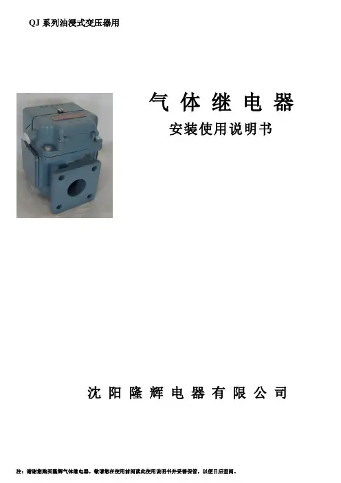
QJ系列油浸式变压器用气体继电器安装使用说明书沈阳隆辉电器有限公司1、概述1.1产品用途QJ 系列气体继电器(以下简称继电器),是油浸式变压器所用的一种保护装置,继电器安装在变压器与储油柜的连接管路上,在变压器运行中由于内部故障而使油分解产生气体造成油流涌动时,使继电器的接点动作,接通指定的控制回路,并及时发出报警信号或切除信号,从而达到保护变压器的目的。
1.2型号组成及其含义注:特殊使用环境代号TH-湿热带型 TA-干热带型 一般型不加表示 1.3使用条件:允许工作温度:-30℃ ~ +95℃2、结构与工作原理2.1气体继电器结构1. 探针 6. 接线端子2. 气塞 7. 上盖3. 重锤 8. 弹簧4. 浮子 9. 干簧接点5. 磁铁 10. 挡板图1 继电器芯子结构2.2气体继电器工作原理变压器正常工作时,继电器内是充满变压器油的,当变压器在运行中出现轻微故障时,因变压器油分解而产生的气体将积聚在继电器容器的上部,迫使继电器油面下降,浮子随之下降至某一限定位置时,磁铁使信号接点接通,发出报警信号。
若因变压器漏油而使油面降低,同样发出报警信号。
当变压器内部发生严重故障时,油箱内压力瞬时升高,将会出现油的涌浪,从而在管路内产生油流,冲击继电器的挡板运动。
当挡板运行到某一限定位置时,磁铁使跳闸接点接通,将变压器从电网中切除。
3、技术参数3.1接点容量 直流 220V 0.3A S ≤5×10⁻³S 交流 220V 0.3A COS Φ≤0.63.2工作特性 表一规 格QJ-50 QJ-80 备 注油速整定范围(m/s ) 0.6~1.20.7~1.5油速刻度偏差±0.1m/s 气体积聚数量(ml )250~300容积刻度偏差±10%继电器 设计序号气体管路通径(标称值),mm取气接头 特殊使用环境代号不带取气接头者不加表示 带取气接头者标注A3.3绝缘性能 表二继电器充满变压器油,在常温下加压200kPa ,持续20分钟无渗漏。
䘀䄀䜀伀刀㈀ 㤀䰀䄀嘀䄀䜀䜀䤀伀 䈀䤀䄀一䌀䠀䔀刀䤀䄀 ⴀ 䰀䄀唀一䐀刀夀Switches, Push Buttons, Selectors12039115Z213033000Momentary push switch orange 22x30 mm16A 250V; faston 6,3x0,8 mm37446912024040120299111203108112111795R663031000RT30280551Z203050000Contactor K3-10ND10 190R TX4kW 3P; 200-240V 50-60Hz 400V - 3 cont.NO + 1 aux NO51717012024011Z213007000Mini contactor B7-30-10-F220-240V 40-450Hz; dim. 47x48x42,5 mm37388312024039Z743009000Contactor 3RT1016-2AP029kW 3P; 230V 50/60Hz 400V - 3 cont. NO + 1 aux NC37389212024075X183011000Contactor 3RT2024-1AL205,5kW 3P; 230V 50-60Hz 400V cont. 3 NO dim. 45x91x88 mm37573612041014Contactor 3RT2024-2AL205.5kW 3P; 230V 50/60Hz; 400V 1NO + 1NC; dim. 97x35x102 mm42629612024012Z683087000Contactor 3TF2001-3AL24kW 3P; 230V 50/60Hz; 400V 3 NO + 1NC37388412023706Z203062000Z683027000Relay 2 contacts NO 230V 50/60Hz 16A 250Vwith DIN bar adaptor37380412025218P620526000Snap action microswitch with lever 4,3X27 mm37431012025193R010534000Snap action microswitch with roller 16A 250Vleverage L=25 mm; 1 contact NO, 1 contact NC30583712024176Z273016000Limit switch microswitch 6A 250V IP6637393812032827DO1FB02230Magnetic microswitch M12x1 L=45 mm 1NO; 50W 1A; cable L=500 mm584470120244776021130029SAVW250030Z203009000Magnetic microswitch A061 1V NO 250Vac 0,004Abulb Ø 6x29 mm - cable L=240 mm37407712114100Magnetic switch M12x1 10÷30Vdc cable L=2000 mm42911912090513DO1DG11734Magnetic microswitch 230Vdim. 10x32x5,5 mm; cable L=500 mm43385512023211P613002000Door electromagnet 36Vdc cable L=100 mm373666120335784GH49G001Floating ball for level regulator Ø 69 mm INOX58344612024066Z203010000Magnet switch support dim. 34,5x19,5x8,5 mm37389912009985R010535000Plate for microswitch dim. 45x30x2 mm3730581203716512168683DO1DL14150Terminal board 4 mmq 600V 20A5844691202834812029280DO1AB01460DO4PRS0041Pressure switch 0,2mbar 1NC, 1NO; Pmax 150mbar5844661203202612049069DO1AB01439DO1AB01475Differential pressure switch 0,4-6 mbar374376120300051203818312147265Pressure switch 20...300 Pa5825251202386212031028120334726021050008RT31011008Z103066000Compact fan 120x120x38 mm - 20W 230V 50/60Hzno cable; faston connection 2,8x0,5 mm; 2550 rpm; ball bearing531364Motors121491601DC07288Gearmotor 3 phase 550W58520912087148DO1DC07056Gear FRC050 Ø 14/25 mm reduction rapport 1:30583604120275731204903412087150DO1DC07052DO1DC07055DO1DC07057Motor 3 phases 370W 230/400/460V 50/60Hzshaft Ø 14x30 mm58315512023189P645902000Motor 3 phases 3000W 230V 60Hz 3548rpm; cable L=260 mm37366212023194P635906000Motor 3 phases 2200W 230V 50/60Hz 2800rpm37366312024916P666014000Retaining ring Ø 125x150x12 mm RG37421712023457P666021000Shaft sealing Ø 125x150x12 mm VITON42281912147306Electromagnetically released spring breake 85W 205Vdc 235NM cable L=660 mm58385712041867Drain pump 30W 220/240V 50Hzinlet Ø 24 mm, outlet Ø 24 mm - Faston 6,3x0,8 mm459511Heating Elements12024214Z121741000Boiler heating elements 9000W 230V L=540 mm, triangular flange H=90 mm, with gasket37396012032899DO1AC02259Heating element 2000W 230Vdim. 540x45 mm; connection M12x1; faston 6,33743811202481612096226P613008000Heating element 2000W 230V UL dim. 265x65 mm; flange 81x28 mm; faston 6,3 mm42891312023247120960234XFP623005000P623005000SAVW130003SAVW130014Heating element 3000W 230V UL dim. 275x65 mm; flange 81x28 mm; faston 6,3 mm428918120232424XFP183002000P633002000Heating element 4000W 230V UL dim. 355x65 mm; flange 81x28 mm; connection M43736701202457712041359P533001000P6330111000Heating element 6000W 230V UL dim. 510x65 mm; flange 81,3x28 mm; faston 6,3 mm37410812024721Z129502000Boiler heating element 12000W 230VUL L=550 mm; triangular flange 92,5x89,7 mm; Øint. 60 mm; with bulb housing L=180 mm; connection M437416812024645Z203601000Tank heating element 2800W 230V dim. 365x102 mm; flange 70x18 mm37413312024282Z101723000Heating element cover Ø 63x67,5x55,3 mm373992Cables12025061P643005000Cable3742531214071212148198GHZ23C01Power supply cable L=4000 mm eyelet Ø 4,2 mm58370812023814P503025000Bi-metal thermostat NTC 50kohm3738421209501812096597Bi-metal thermostat 110° 250V 10A faston 6,3 mm4290161203243212032731DO1AG11130DO1DG11130Safety thermostat 1P 0÷90°Ccoated capillary L=3000 mm; bulb Ø 6x93 mm; D-shaft Ø 6x4,6 mm3743771209761112126296DO1DG11135Safety thermostat 1P 220°Ccapillary L=1900 mm, bulb Ø 6x58 mm, 16A 240V58258512023546Z953003000Gasket Ø 11x27x8,5 mm373738Drain valves12024781P302120000Electric drain valve N.O. 220/240V 50/60Hznormally open; inlet Øext 50 mm; outlet Øext 50 mm; overflow pipe Øext 35 mm; mod. MDB-O-23741891202626712147216SAVZOD0112SAVZOD0264Electric drain valve N.C.coil 230V 50/60Hz 0,20-0,17A; inlet Ø 76 mm; outlet Ø 80 mm; overflow pipe Ø 35 mm583854Drain valves12137690Electric drain valve N.O. 230V 50/60Hz Ø75,5 mm - Ø 79,5 mm42670912024404P532103000Electric drain valve N.O. 230V 50/60Hz 0,20-0,17Ainlet Ø 76 mm; outlet Ø 80 mm; overflow pipe Ø 35 mm37405212093146Air brake4299221070312025161Z701135000Solenoid valve 180° - 1 way - 220/240V 50/60Hz - Ø 10,5 mmwith fastons; inlet Ø 3/4" with filter; Tmax 90°C43540912023794P255001000Solenoid valve 180° - 2 way - 220/240V 50/60Hz - Ø 10,5 mmwith fastons; inlet Ø 3/4" with filter and reducer 14 lt/min; Tmax 90°C3738311202392112115418P443018000P443073000Z6111223000Z611123000Solenoid valve 180° - 3 way - 220/240V 50/60Hz - Ø 10,5 mmwith fastons; inlet Ø 3/4" with filter; Tmax 90°C2001211202408312097038P443042000Outlet pressure reducer 2,5 lt/min [brown-Inv]20011812041072Solenoid brass valve G1" - 4W 230V 50/60Hz43001112157686Electro-pneumatic valve 4/2dim. 3,5x1,8x51,5 mm583864Solenoid Valves and Reducers12028386QUINCA0161Solenoid valves 230Vac 50/60Hz 3/2 NC58386512023551Z102305000Solenoid body EV220B 3/4"L=90,5 mm37374012008907S205023000Nipple 1/2"÷1/2" - L=27 mm - brass51924912018536S102122000Rubber holder 1/2'' - outlet Ø 9 mm Ltot.=67 mm37343112009102Pipe fitting 90° 1/2"M58231412019829U565032000Rear left pipedim. 545x70xh95 mm37351312019731U565031000Rear right pipeØ4 mm; dim. 545x100x75 mm3735071202502612152912P630704000Formed hose 90°Øint.72 mm; dim. 400x130 mm45974712044165Formed hose Øint. 75 mm427755Hoses110000663702400000Hose EPDM Ø 5x12 mm L=2300 mm Tmax 110°C435233110000833676900003676900000S102121000Z271101000Z631121000Hose EPDM Ø 10x17 mm (sold by meter)Pmax 10 bar; working temp. -35°C÷110°C61236012024115Z602121000Rubber feeder hose 3/4" L=1500 mm straight connection + 90° plasticconnection; ring nut in nickel-plated brass Ø3/4"F; pipe Ø 13x19 mm; Pmax 10 bar;Tmax 90°C; WRC/WRAS/VDE approved52432412007747P634021000Drain pipe Ø 50x60 mm dim. 620x220x140 mm42311712023666Z220903000Drain pipe PPE Ø 19 mm 90°+ Ø 22 mm 180° L=2000 mmmuffs 180° Ø int/ext 19/24 mm, muffs 90° Øint/ext 22/27 mm, Øext hose 24 mm37072312022957Drain box58523112023537Z710708000Ring nut 1" 1/2H=15 mm; CH5037373712038179DO1SK00016Air filter Ø 260x430 mm374433Transmission components12023273P615902000V-ribbed belt L= 1300 mm 8 ribs37367912023269P625903000V-ribbed belt L=1600x18,8x3,5mm 8 ribs37367712007744P635908000V-ribbed belt L=1663x3,5x28,4 mm 12 ribs58303212049376V-ribbed belt L=1752x3,5x19mm 8 ribs42636812018841P645901000V-ribbed belt L=1854x3,3x19 mm 8 ribs37345812046375V-ribbed belt L=1992x3,5x28 mm 12 ribs42636612023249P646013000Drum pulley31965712023222P540702000Ice containerdim. 190x470x305 mm42339212128087Rep cierre ln-35dim. 800x765 mm428706Structural components12003389Z270337000Paneldim. 560x116x18,5 mm42199312023338P620504000Door handle 100x90 mm37368712147485Door handle58386112025202P620514000Shaft Ø 6x55 mm37430312023239P620527000Semicomp door. fagor 13.1837366812023347P620505000Hingeshaft Ø 6x15 mm37369112030807K005B50072Manometer Ø 62 mm 0 ÷ -1bar58495212010155Q302061000Snap ring Øint. 6x0,7 mm37313412009802Q301036000Snap-ring Øint. 103 mm37299812010103Q272020000Radial snap ring INOX Øest 9x0,8 mm43824512023427P620525000Ring Øint. 12,5 mm wire Ø 1,3 mm58200612025215P610506000Bush Ø 6x12x12 mm37430812025100P680511000Bushing Ø 16x22/28x25 mm42289912010251Q222012000Hexagonal nut M6x8 self-locking - INOX36294312009839Q162020000Hexagonal nut M4 - H=3,2 mm INOX CH736294012010284Q162030000Hexagonal nut M5 - H=4 mm INOX33704512010036Q881302000Hose clamp Ø 12÷22/9 mm - INOX43848012009997Q881305000Hose clamp Ø 25÷40/9 mm - INOX44169912009986Q881306000Hose clamp Ø 32÷50/9 mm - INOX43846412009962Q881307000Hose clamp Ø 40÷60/9 mm - INOX518655120009933Q881324000Hose clamp Ø 50÷70/12 mm - INOX43846312145377Support42727312009953Q242010000Tooth lock washer M358185912009928Q242020000Tooth lock washer Ø int.4/est.7,8 mm INOX37303812009872Q262040000Grower washer Ø 6,3 mm INOX35821112009944Q232030000Flat washer Ø 5,5x10x1 mm - INOX61277012010267Q302022000Flat washer Ø 6,3x15,7x1,2 mm37319912009868Q232040000Flat washer M6 Ø 6,4x11,6x1,6 mm INOX4326051201011012010268Q232050000Q302025000RT13080160Flat washer Ø 8,4x16x1,2 mm DIN125A37320012010235Q232060000Flat washer M10 INOX Ø10,6x20x2 mm32201512010278Q032021000Raised countersunk head screws M4x10 mm37320612010084Q052046000Cylinder head bolts M6x20 mm INOX37310112010226Q032031000Hexagon head screw TE M5x10 mm - INOX [10 pcs]52249712010221Q012032000Hexagonal head screw TE M5x16 mm - INOX [10 pcs]32626312010186Q011342000Q012042000Hexagon head screw TE M6x16 - INOX35811812010056Q012056000Hexagon head screw TE M8x40 mm - INOX [10 pcs]52268712010213Q032032000Flat-headed bolts TC M5x16 mm37317012010262Q042022000Countersunk screw M4x15 mm37319612009876Q151320000Sheet metal screws M4x6 mm37302212023360P666102000Bearing 125/70/3142282312023334P666101000Bearing Ø 105x190x36 mm422827120379971ED40207Bearing ucfc 207433323120039221203836412038446121278381215482213P620516013P6205310P620516000Door locking mechanism 205V dim. 180/220x100 x53 mm5824801202841112147483Door lock switch 220/240V 50Hz58386012021912P627816000Cover 120x50x2 mm58248112016778P620511000Pin for handleØ6x29 mm AISI 30337329012025182P620529000Unlocking pin Ø 7xLtot. 22,5 mm5820051202436112122779N103033000Thermostat knob Ø 72 mm D-shaft Ø 6x4,6 mm41525612024758P530503000Door glass Ø 385x55 mm37418412024250P440503000Door glass Ø 305x40,5 mm37398012024980P630111000Friction damper 140N Ø 28/185-295 mm RD10 - hole Ø 10,2 mm37423512025078P620126000Friction damper 90N Ø 28/185-280 mm37425812025077P620115000Friction damper 120N Ø 28/187-280 mm37425712147246SAV W08 0039SAVW080039Friction dumper 120N Ø 28/170-265 mm hole Ø 10 mm58385512025076P540201000P630110000Friction damper 250N Ø 28/170-300 mm hole Ø 10,2 mm37425612147247SAV W25 0006SAVW250006Friction dumper 250N Ø 28/190-280 mm hole Ø 10,2 mm5838561202349212049230P680220000Friction damper Ø 45,5xLtot. 330 mm hole Ø 10 mm42766512157708QUI NCA 0359QUINCA0359Shock absorber Ø 70xLtot. 345 mm42555112147399QUI NCA 0360QUINCA0360Gas friction dumper Ø 40x190/275 mm hole Ø 12 mm58385812147406Tension spring Ø 42x116xLtot200 mm58385912023383P620510000Spring closing37370112033583SPQ800622PFriction damper [KIT]374389Photocells1202809012147195Speed sensor M12x50 mm cable L=2000 mm58385312024424T133008000Screw M3x8 mm37405812025260T133007000Spacer L=16 mm M337432812023354P613019000Pcbdim. 235x140 mm37369312024197P613025000Pcbdim. 235x140 mm58185712025606Plc TWD LCAA dim. 70x95x90 mm58385212024780P613018000Pcbdim. 115x140 mm37418812017891P623017000Pcb with main switch dim. 50x30 mm3733831202649612147280ELEELE0089Pcbdim. 135x135 mm5852341203814712147287ELEELE0109Display board dim. 100x150 mm4333631211948812155387Display TFT 4,3"42678112043487PLC programmed 3kw (lr-25)42875612024634SAVW080104Z218030000Relay pcbdim. 75x35 mm37412812023112P640325000Pcb supportdim. 120x44x14 mm58185812023293P623026000Cable L=675 mm4533921212081512168823Pcbdim. 155x324 mm42968112024921P623023000Pcb LED37421812031344DO1DH12314Temperature probe L=175 mm bulbo Ø 4x10 mm; flange 17x10 mm42478112025036Z713028000Temperature probe NTC 64k oHm probe Ø 6x14 mm; -40 ÷ +110; cable L=300 mm3742501202948712147283ELEELE0098Temperature probebulb Ø 6x64 mm; cable L=2000 mm37435712120341Cable PTC with rectifier bridge582004Probes12024049N503017000Gasket Ø 23x35x7,5 mm3738951202672612127829DO1DC00001Inverter ABB 3P 370W 200/240V 6.1A5840111202613012026131DO1DC00003DO1DC00063Inverter ABB 3P 1100W 200/240V5844671202334312040601P623002000Inverter G110 1 phase 200/240V 47/63Hz 19,7Aoutput 3 phases 0-230V 0-550Hz 7,8A; 1,5kW 200/240; dim. 120x160x140 mm3736891203844213P6330050Inverter G110 1 phase 200/240V 47/63Hz 27,2Aoutput 3 phases 0-230V 0-650Hz 11A; 2,2kW 200/240V31783412018961P610319000Membrane keypads 640x160 mm37346412023797Z468001000Membrane keypads 45x400 mm37383212023260P636108000Gasket373675Gasket for laundry1200776712024455P440502000P610508000Oblò gasket Ø 247x305 mm37406512023284P620528000Door gasket Ø 395 mm37368012023475P660535000Oblò gasket Øext. 590x33,5 mm37371712147521Drum gasket583862O-rings12009912Q307036000O-ring 1,78x5,28 mm EPDM37303112009926Q307077000O-ring 3,00x128 mm3730371209314512122182O-ring 3,53x24,99 mm NBR410444120100401211831912154789Q307044000O-ring 5,34x56,52 mm NBR435067Flat gaskets12025148P636005000Flat gasket Ø 114x160x4,3 mm374280Laundry parts1203490812147375QUINCA0086Ironing band 105x410 mm37439610222010261202944612147376QUINCA0087Ironing band 200x1660 mm3743561203717712037305DO1KA00422QUINCA0091Polyester/Meta-Aramid guide tape 13mmx10mt Tmax 230°C331471120346231214737712147908121562021BE03500QUI NCA 0088QUINCA0088Self-adhesive elastomere strip for ironers (sold by meter))3294271202775712149876GR10003000Steel wool band width 100 mm [8 Kg]317321120299561214741412150171QUINCA0476Plush clothing 2020x495x3 mm374362。
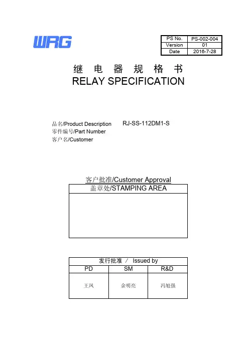
PS-002-004012016-7-28客户名/CustomerRELAY SPECIFICATION零件编号/Part Number品名/Product Description RJ-SS-112DM1-SDate Version PS No.继 电 器 规 格 书冯旭强余明亮王凤客户批准/Customer Approval 盖章处/STAMPING AREAR&DSM PD发行批准 / Issued by序号担当00凌剑冰01凌剑冰2016-7-28增加黄山工厂描述变更履历/HISTORY日期变更项目2015-4-13初版1零件清单/PARTS LIST123 4 5 6 7 8 9 10 11 12 13 14 15 16Ver01RG3015010GN6-30 M8XRG301RG301FLAME CLASSUL FILE No.E171666E53664E171666E171666TYPE/TREATMENT型号/处理方式镀镍Vicryst R850Part零件名No.材质MATERIAL镀镍Nickel Plated镀镍Nickel PlatedNickel Plated3UEW 155(F Class)镀锡Base基座骨架Bobbin外壳Case推片CardSolder Coated挂钩Hinge可动弹片C Terminal轭铁Yoke衔铁Armature线材Wire可动接点C ContactM接点M ContactE171666线圈端子Coil Terminal铁芯CoreM端子M TerminalE234867PS-002-004E164502Epoxy胶水UV GlueSealing ResinAg Alloy铜包钢Cu coverd Steel聚氨脂漆包圆铜线Cu Alloy铜合金Polyurethane copper wire环氧树脂Steel铜合金Cu Alloy银合金Ag Alloy银合金Cu Alloy铁LCP铁Steel铁Steel铜合金PBTUV胶PBTPBT2.性能/SPECIFICATIONS2.1驱动部分/COIL SPECIFICATIONS2.1.1额定电压12VDC(在20℃时)Rated Coil Voltage12VDC at 20℃2.1.2额定功率0.45W(在20℃时)Nominal Power0.45W at 20℃2.1.3线圈电阻320Ω±10%(在20℃时)Coil Resistance320Ω±10%(at 20℃)2.1.4额定电流37.5mA±10%(在20℃时)Nominal Current37.5mA±10%(at 20℃)2.1.5吸合电压9VDC以下(在20℃时)Operate Voltage9VDC Max. at 20℃2.1.6释放电压0.6VDC以上(在20℃时)Release Voltage0.6VDC Min. at 20℃2.1.7最大连续施加电压18.6VDC Max. 155%额定电压Max Power18.6VDC Max. 155%of Nominal2.2开关部/CONTACT SPECIFICATION2.2.1开关类型单刀常开型Contact Configuration 1 Form A2.2.2接点规格10 A 250VAC(阻性负载)Contact Rating10 A @250VAC (Resistive)2.2.3接触电阻100mΩ以下, (初期值,DC 24V/1A条件下)Contact Resistance100mΩ Max. @ Initiate, DC 24V/1A500mΩ以下, (寿命试验后,DC 24V/1A条件下)500mΩ Max. @ After Life, DC 24V/1A2.2.4吸合时间20ms 以下(额定电压下)Operate Time20ms Max. @ Rated Voltage2.2.5释放时间10ms 以下(施加额定电压后断开时)Release Time10ms Max. @ Rated Voltage2.2.6最大动作频率300次/分(无负载)Max. Switching Rate300ops./min. (no load).6次/分(额定负载)6ops./min. (Rated load)Ver 01 PS-002-0042.3特性/GENERAL SPECIFICATION2.3.1绝缘电阻1000MΩ以上(500VDC)Insulation Resistance1000MΩ Min@500VDC2.3.2介质耐压1000VAC/分钟(接点间)Dielectric Strength4000VAC/分钟(线圈/接点间)1000VAC@50/60Hz 1 min.(Between Open Contacts)4000VAC@50/60Hz 1 min.(Between Coil and Contacts)2.3.3电气寿命1×10⁵次以上(额定负载,气孔打开)Electrical Life1×105*******************************.2.3.4机械寿命1×10⁶次以上(无负载)Mechanical Life1×106Cycle Min. @no load2.3.5使用环境温度-40~105℃(无凝结时)Temperature-40~105℃ @no condensation2.3.6使用环境湿度20~85%RH(无凝结时)Humidity20~85%RH @no condensation2.3.7抗振动耐久10~55Hz,双振幅 1.5mmVibration Mechanical10 to 55Hz, 1.5mm double amplitude误动作10~55Hz,双振幅2.5mmOperational10 to 55Hz, 2.5mm double amplitude2.3.8抗冲击耐久980m/s2 Min(约100G)Shock Mechanical980m/s2 Min(100G approximately)误动作98m/s2 Min(约10G)Operational98m/s2 Min(10G approximately)2.3.9重量 5.7克Weight 5.7g2.3.10焊锡条件5s@ 260°C (波峰焊)Solder ability5s@ 260°C (wave soldering)2.4端子性能/TERMINAL CHARACTERSITICS2.4.1端子强度5牛/10秒,任意方向静态压力,无异常,但端子弯曲可以Terminals strength5N 10s,Thereshall be no abnormalities.(The curving of the terminal shall be acceptable)2.4.2可焊性260±5℃ 3s,端子头部3mm部分90%以上的面积有锡覆盖Terminal solderbility(无铅焊锡)260±5℃ 3s,In Case of lead lead free solder,90% of the dipped portion shall be solderd.2.4.3耐热性5s @ 260°C,端子头部3mm浸入锡中,无异常发生Soldring Heat Resistance5s @ 260°C,There shall be no abnormalities. (wave soldering)01 Ver PS-002-0042.5安全规格/SAFETY REQUIREMENTS2.5.1UL规格认定(UL & C-UL)档案号:UL(UL & C-UL)File No.:2.5.2CQC标志认证证书编号:CQC Certificate No.:2.5.3TUV规格认定证书号TUV Certificate No.2.5.4产品符合ROHS和REACH要求。

家电领域-继电器手册中汇瑞德连接更美好的未来Churod Electronics中汇瑞德电子股份有限公司Home Appliances Field - Relay Manual深圳市龙华大浪街道同盛社区华荣路联建科技7栋3楼 E-mail:anmu@anmutech.com Tel:+86-755-2961 5180东莞市中汇瑞德电子股份有限公司,是全球领先的继电器,接触器,PDU产品的研发、制造生产厂商,为全球提供继电器,接触器产品的解决方案。
公司成立于2006年, 目前在国内东莞、芜湖两地共有三大生产基地,拥有多家全资、控股子公司,产品涵盖了继电器、接触器、低压电器、高低压设备、精密非标自动化设备等多个类别。
其中,继电器产品作为中汇瑞德的主营业务,共有三十多个系列、一千多种常用规格,年生产能力达到5亿只。
产品广泛应用于家电领域、工业控制领域、光伏领域、通讯电源领域、汽车领域等行业。
并在多个国家和地区设立办事处及售后服务网络,具备了全球化的市场运作和技术服务能力, 发展速度及配套能力居同行业之首。
公司的管理团队、技术团队凝聚了拥有十多年以上行业标杆企业的继电器研发、制造、管理经验的人才,致力于以继电器的自主创新、继电器品质提升为基础的产品研发与技术创新。
目前公司已取得60多项专利技术,通过了ISO9001,ISO14001,IATF16949的体系认证。
连续两次获得高新技术企业证书。
公司的试验室通过了欧洲TUV,北美UL、中国CNAS认可的实验室。
我们追求卓越的产品品质,秉承“以质取信,以诚取胜”的经营方针,通过贯彻先进的质量理念,不断完善质量管理体系,持续推行产品质量先期策划、过程质量控制、供应链管理等工作,产品质量达到国际先进水平,赢得了国内外广大客户的赞美。
中汇瑞德愿与全体员工一起共同奋进,携手全球客户,共进共享,实现科技给生活带来的变化和服务。
Company Introduction公司简介空调,冰箱,洗衣机,电热水器,厨卫电器,小家电、抽油烟机、微波炉等家电领域应用CHF/CHFN 系列CHS 系列CHD 系列CHI03 系列CHE/CHEN 系列CHMN 系列CHAC 系列A1 系列A2 系列CHM 系列CHW 系列CHZ01 系列CHZ02 系列CHZ03 系列CHZ05 系列060912151821242730333638414447产品目录Catalog核心竞争优势Core Competitive Advantage3~10A 小型功率继电器一组常开型符合UL/cUL,TUV,CQC标准4,000VAC线圈和接点间耐压强度线圈灵敏型和标准型可选符合RoHS要求符合REACH SvHC要求可选无卤型号可选耐灼热丝 UL File NO. E341422TUV File NO. R50174892CQC File NO. CQC100020436061. 产品系列2. 密封形式 V:透气孔外壳(耐助焊剂,RT II类)S:密封外壳(耐清洗型, RT III类)3. 触点组数 1=一组触点4. 额定线圈电压03=3VDC 05=5VDC 06=6VDC 09=9VDC12=12VDC 18=18VDC 24=24VDC 48=48VDC 5. 线圈功耗L/I = 灵敏型(200mW)D/H = 标准型(450mW)6. 触点构造A = 常开型(SPST)9. 额外的数字或字母A1 -S -1 12 H A 2 F 0007. 触点材质8. 负载容量 Blank = Class (105℃)F=Class F (155℃)DA/LA:=无=Ag IA/HA:=无=AgCdO IA2/HA2:=无=AgSnO000-999,AAA-ZZZ,aaa-zzz or 空白,只表示指定客户要求备注:(1) 外形尺寸中的参考公差:外形尺寸≤1mm,参考公差为±0.2mm; 外形尺寸>1mm且≤5mm,参考公差为±0.3mm; 外形尺寸>5mm,参考公差为±0.5mm。
继电器说明书继电器说明书1. 简介继电器是一种电气开关装置,用于控制小功率信号操作较大功率电路。
它在自动化系统中广泛应用,承担着信号放大、保护、控制等功能。
本文档将介绍继电器的工作原理、使用方法以及注意事项。
2. 工作原理继电器由线圈和触点组成,通过电磁感应原理实现工作。
当线圈通电时,产生的磁场使触点吸合或断开,从而控制外部电路的开关状态。
3. 继电器的分类3.1 电磁式继电器电磁式继电器是最常见的继电器类型,主要可分为单联触、双联触和多联触等。
根据工作特性可分为常开型和常闭型。
3.2 固态继电器固态继电器采用固态器件(如半导体器件)实现电路的控制和隔离。
与传统的电磁式继电器相比,固态继电器具有响应快、寿命长、可靠性高等特点。
3.3 保护继电器保护继电器主要用于电力系统中的故障保护,能够侦测电流、电压等参数,并在异常情况下及时切断电路以保护设备和人员的安全。
4. 继电器的使用方法4.1 连接方式继电器通常需要与外部电路配合使用。
在使用继电器时,需要按照电气图纸中的接线方式进行连接,确保线路的正确性和稳定性。
4.2 控制信号继电器的线圈需要接收控制信号才能工作。
控制信号可以是直流或交流电压,需要根据继电器的额定工作电压进行选择。
4.3 触点容量继电器的触点容量是指继电器可以承受的最大电流和电压。
在选择继电器时,需要根据实际需求考虑触点容量,确保继电器能够正常工作。
5. 继电器的注意事项5.1 工作环境继电器在使用过程中需要注意工作环境的条件,如温度、湿度等。
过高或过低的温度、潮湿的环境都可能影响继电器的性能和寿命。
5.2 安装位置继电器的安装位置应远离高温、火源等危险因素,并保持通风良好。
同时,要确保继电器与其他电气设备之间的安全距离,避免干扰和故障。
5.3 维护保养定期检查继电器的接线端子是否松动,观察继电器的工作状态。
如发现异常,应及时处理或更换继电器。
6. 总结继电器作为一种重要的电气开关装置,在自动化控制系统中扮演着重要角色。
常用继电器使用说明继电器是一种根据输入信号的变化,接通或断开小电流电路,以实现自动控制和保护功能的电器。
继电器的分类方法很多,按输入信号的性质可分为:电压继电器、电流继电器、速度继电器、压力继电器等;按工作原理可分为:电磁式继电器、电动式继电器、感应式继电器、晶体管式继电器和热继电器等;按输出方式可分为:有触点式和无触点式。
继电器主要由感测机构、中间机构和执行机构3部分组成。
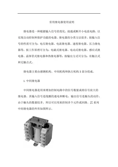
1.中间继电器中间继电器是用来增加控制电路中的信号数量或将信号放大的继电器。
其输入信号是线圈的通电和断电,输出信号是触头的动作,由于触头的数量较多,所以可以用来控制多个元件或回路。
JZ系列中间继电器的外形如图所示。
(1)结构中间继电器由线圈、静铁心、动铁心、触头系统、反作用弹簧及复位弹簧等组成。
JZ7型中间继电器的结构如图所示。
(2)选用中间继电器主要根据被控制电路的电压等级、所需触头的数量、种类、容量等要求来选择。
(3)安装与使用中间继电器的使用与接触器相似,但中间继电器的触头容量较少,一般不能在主电路中应用。
中间继电器一般根据负载电流的类型、电压等级和触头数量来选择。
2.热继电器热继电器一般作为交流电动机的过载保护用,热继电器有两相结构、三相结构和三相带断相保护装置等3种类型。
JR系列热继电器的外形如图所示。
(1)结构它是由热元件、触头系统、动作机构、复位机构和整流电流装置组成。
其结构如图所示。
(2)工作原理使用时,将热继电器的三相热元件分别串接在电动机的三相主电路中,常闭触头串接在控制电路的接触器线圈回路中。
当电动机过载时,流过电阻丝的电流超过热继电器的整定电流,电阻丝发热,主双金属片向右弯曲,推动导板向右移动,通过温度补偿双金属片推动推杆绕轴转动,从而推动触头系统动作,动触头与常闭静触头分开,使接触器线圈断电,接触器触头断开,将电源切除起保护作用。
电源切除后,主双金属片逐渐冷却恢复原位,于是动触头在失去作用力的情况下,靠弹簧的弹性自动复位。
控制继电器工程技术人员培训教材目录第一章小型电磁继电器 6.5.2 使用温度范围1.前言 6.6 动作时间和释放时间2.继电器的结构及动作原理 6.7 环境特征3.继电器与半导体开关的比较 6.7.1 温湿度特性4.继电器的种类 6.7.2 耐冲击和振动特性4.1 继电器分类 6.8 故障4.2 有悠久历史的绞链式继电器 6.9 寿命4.2.1 通讯用继电器 6.9.1 机械寿命试验4.2.2 一般产业用继电器 6.9.2 电气寿命试验4.3 近代的绞链式继电器 6.10 工业规格和安全规格4.3.1 PCB印刷线路板继电器 6.10.1 工业规格4.3.2 超小型继电器的形状和尺寸 6.10.2 安全规格4.3.3 超小型继电器的端子形状和端子配置4.3.4 防止焊剂渗入的超小型继电器第二章继电器的选择和使用方法4.3.5 高灵敏超小型继电器 1 前言4.3.6 自保持型继电器 2 继电器的选择4.3.7 高频继电器 2.1 继电器的选择原则4.4 舌簧继电器 2.2 关于继电器的接点5继电器的结构部件及其使用材料 2.2.1 根据接点负载的种类确定继 5.1 接点电器形式5.1.1 接点形状 2.2.2 根据接点负载电流大小来5.1.2 多层接点选择继电器5.1.3 接点材料 2.2.3 对接点的开闭频度要特别注意 5.2 接点簧片材料5.3 磁路材料 2.3 关于激磁线圈5,4 绝缘材料 2.3.1 交流驱动和直流驱动6绞链式继电器的主要性能和特性 2.3.2 特殊的驱动回路6.1 接触电阻 2.3.3 线圈功耗和线圈电阻6.1.1 概述 2.3.4 动作电压和释放电压6.1.2 接触面的污染和接触电阻 2.3.5 热线圈和冷线圈6.1.3 接点的净化 2.3.6 环境温度和线圈允许电压6.1.4 接触压力及其接点摺动和接触电阻5. 6.1.5 塑料密封和接触电阻 2.4 动作时间和释放时间6.1.6 双子接点可以提高接触可靠性 2.5 介质耐压和绝缘电阻6.1.7 电压、电流和接触电阻 2.5.1 继电器特征6.1.8 接点消耗和接触电阻 2.5.2 工频与介质耐压6.1.9 接触电阻的测量方法 2.5.3 耐浪涌电压6.2 接点熔着 2.5.4 绝缘电阻6.3 介质耐电压和绝缘电阻 2.6 环境关系6.4 动作电压和释放电压 2.6.1 周围温湿度6.5 继电器温升和使用温度范围 2.6.2 周围环境气氛6.5.1 温升 2.6.3 冲击和振动2.7 关于安装2.7.1 外形尺寸2.7.2 继电器安装和引出端接线2.7.3 印刷线路板用超小型继电器的外形尺寸和结构2.7.4 印刷线路板用超小型继电器的安装2.8 故障率和寿命3 继电器的最佳使用方法3.1 硅及其化合物是继电器大敌3.2 外界强磁场会影响继电器的动作电压和释放电压3.3 负载的接线方法3.4 继电器安装的注意事项3.5 用晶体管来驱动继电器3.5.1 驱动回路3.5.2 晶体管选择3.5.3 防止反电压3.5.4 用晶体管驱动继电器的注意事项 3.6 接点开闭时要注意交流负载相位3.7 闭锁继电器的使用3.7.1 闭锁驱动回路的实例3.7.2 闭锁驱动回路接线时的注意事项 3.7.3 其他使用方面的注意事项3.8 印刷线路板实装3.8.1 向印刷线路板上安装继电器时的布线设计3.8.2 手工焊接时的注意事项3.8.3 自动焊接时的注意事项3.8.4 清洗工程的注意事项第一章小型电磁继电器1 前言通俗一点说继电器就是一个输出回路的开与关是由输入回路的信号状态来确定的电子元件。

∙继电器名词术语23印刷电路板式插入式及插座式快速连接式4∙要保持继电器的初始性能,应小心避免继电器的掉落或撞击等机械故障。
∙在正常使用情况下,继电器设置的外壳不要拆开,否则,将无法保证继电器的初始性能。
∙建议在标准温度、湿度和具有少量灰尘、SO2、H2S或有机气体的环境中使用继电器,特别是在含有硅基树脂的环境中,极易造成触点失误,否则,应考虑优选塑封继电器。
∙线圈供电电源应达到规定的额定电压范围,直流线圈应以方波驱动,交流线圈以正弦波驱动。
∙确保线圈连续工作电压不超过允许的最大连续工作电压。
∙应避免触点电路的通断电压、电流超过规定值。
∙详细规范中所列出的额定通断功率及寿命只能作为参考,这是因为触点的物理、化学变化和触点寿命随负载类型和动作条件的变化有很大的差异,因此,使用前应仔细检查负载类型及动作条件是否符合要求,否则应事先声明。
∙不要超过样本中所列出的环境温度范围。
∙如用于自动焊接,应选用抗焊剂式或塑封式继电器。
∙当对塑封继电器进行清洗时,应使用氟里昂或酒精作为清洗剂。
∙对所有类型的继电器,都应尽量避免使用超声波清洗,这是因为超声波清洗会危害触点。
∙作为参考,对于快速连接式引出端的继电器,应配用标准的端子,使用的快速安装推力为4~7 kgf。
∙有些继电器在出厂时,外壳顶部的排气孔会封有透明胶带,当继电器安装完毕并在实际使用之前,应将透明胶带撕去,这样有助于提高继电器的使用寿命。
∙这一条特别重要:不能将继电器触点并联来切换大于一组触点切换能力的负载。
因为,触点接通、断开不可能绝对同步,这将导致由一组触点承受全部的负载而加速失效。
∙为保证正确使用继电器,请仔细阅读继电器详细规范。
56圈电阻)继电器即可以动作,但此时并不保险,其中驱动电压和电阻的变化以及温升等因素都可能使已吸合的继电器释放或不稳定。
因此,要保证继电器可靠工作,就必须使线圈中的电流值为吸合电流的1.5~2倍,而且,受环境温度或线圈自身温升的影响,线圈电阻大致以0.4%/︒C 的比例变化,这可能会使吸合电压和释放电压发生变化;如果温度升高,则吸合电压和释放电压会相应增大,对于这一点应特别注意。
使用说明书一.工作原理润滑油站由油箱、2套双联油泵装置(1套工作、1套备用)、一套独立的油冷却器系统、两个油滤器以及电控柜、仪表盘、管道、阀门等组成。
工作时,主系统油液由油泵从油箱吸出,经过单向阀、溢流阀、双筒过滤器、流量调节机构,分别送到设备目标点。
一支路经双联泵一G3/4油口送到风机风量调节系统作为动力油(其压力为28bar,流量37L/min),另一支路经双联泵一G3/8的油口后分为4路(其压力为1.1bar,流量2×6.5L/min、2×7L/min,可调节),经流量指示器送往风机、电机润滑点进行润滑。
润滑与控制油路经系统回油管流回油箱。
油站的最高工作压力为28bar。
根据润滑点的要求,通过调节溢流阀确定使用压力。
当油站的工作压力超过溢流阀的调定压力时,溢流阀将自动打开,多余的油液流回油箱。
另一冷却系统由电机,泵,阀,管件等独立构成,可随时对冷却系统进行起停.该润滑油站具有过滤、冷却、加热等装置和安全连锁、自动控制、报警等功能。
二.结构技术特点1.采用双筒过滤器,更换滤芯时不需停机,滤芯堵塞时自动报警。
2.相关控制点均配有就地机械式仪表,以方便就地观测。
3.采用冷却效果优良的进口板式的冷却器,冷却面积达到2.8m2,冷却效果好,可保证油站长期运行,延长维护周期。
冷却器配有旁通阀,当冷却器堵塞时,油液压力达到旁通阀的设定压力3.5bar时,油液不经过冷却器自动途经旁通阀回到油箱。
4.油站在泵出口分别设有溢流阀,可有效的设定系统压力,保证控制油及润滑油输出的压力稳定,双重消除系统压力脉动。
采用PARKER 低压溢流阀,该阀具有压力稳定、压力脉动小等特点;避免了高压溢流阀在低压区使用时出现因压力波动引起的检测组件损坏及润滑部位泄漏。
5.油站配有液位开关、温度开关、电加热器、空滤器等;主控制油路配有溢流阀出口就地压力表、过滤器差压开关、输出就地压力表、电子式压力开关(带数字显示、PARKER德国产);四条润滑油路配有溢流阀出口就地压力表、过滤器差压开关、输出就地压力表、温度开关、电子式压力开关(带数字显示PARKER德国产)。
Relay terms and wizard继电器的使用通常人们所说的产品可靠性是指产品的工作可靠性,其被定义:在规定的条件下和规定的时间内,完成规定功能的能力。
它由产品的固有可靠性和使用性组成,前项由产品的设计和制造工艺决定,而后者则与用户的正确使用及生产厂家售前、售后服务有关。
用户使用时应注意以下各项1、线圈使用电压线圈使用电压在设计上最好按额定电压选择,若不能,可参考温升曲线选择。
使用任何小于额定工作电压的线圈电压,将会继续影响继电器工作,注意线圈工作电压是指加到线圈引出端之间的电压,特别是用放大电路来激励线圈,务必保证线圈两个引出端的电压值,反之超过最高额定工作电压时也会影响产品性能,过高的工作电压会使线圈温升过高,特别是在高温下,温升过高会使绝缘材料受到损伤,也会影响到继电器的工作安全,对磁保持继电器,激励(或复归)脉宽不小于吸合(或复归)时间的3倍,否则产品会处于中位状态。
用固态器件来激励线圈时,其器件耐压至少在80V以上,且漏电流要足够小,以确保继电器的释放。
2、瞬态抑制继电器线圈断电瞬间,线圈上可产生高于线圈额定工作电压值30倍以上的反峰电压,对电子线路有极大的危害,通常采用并联瞬态抑制(又叫削峰)二极管或电阻的方法加以抑制,使反峰电压不超过50V,但并联二极管会延长继电器的释放时间3-5倍,当释放时间要求高时,可在二极管一端接一个合适的电阻。
3、多个继电器的并联和串联供电多个继电器并联供电时,反峰电压高(即电感大)的继电器会向反峰电压低的继电器放电,其释放时间会延长,因此最好每个继电器分别控制后再并联才能消除相互影响,不同线圈电阻和功耗的继电器不要串联供电使用,否则串联回路中线圈电流大的继电器不能可靠工作,只有同规格型号的继电器可以串联供电,但反峰电压会提高,应予以抑制,可以按分压比串联电阻来承受供电电压亮出继电器的线圈额定电压的那部分电压。
4、触点负载加到触点上的负载应符合触点的额定负载和性质,不按额定负载大小(或范围)和性质施加负载往往容易出现问题,只适合直流负载的产品不应用于交流场合。
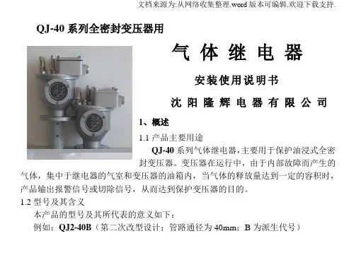
QJ-40系列全密封变压器用气体继电器安装使用说明书沈阳隆辉电器有限公司1、概述1.1产品主要用途QJ-40系列气体继电器,主要用于保护油浸式全密封变压器。
变压器在运行中,由于内部故障而产生的气体,集中于继电器的气室和变压器的油箱内,当气体的释放量达到一定的容积时,产品输出报警信号或切除信号,从而达到保护变压器的目的。
1.2型号及其含义本产品的型号及其所代表的意义如下:例如:QJ2-40B(第二次改型设计;管路通径为40mm;B为派生代号)1.3使用条件工作温度:-30℃~ +95℃2、气体继电器结构及工作原理2.1气体继电器外部结构气体继电器外部结构如图1、2、3、4所示;内部浮子及两个磁性开关C、D构成,开关吸合将报警信号或除切信号通过接线端子输出。
图1 QJ1-40型图2 QJ2-40A型图3 QJ2-40B型1.油位视察窗2.壳体3.注油塞4.放气塞5.探针6.接线盒7.接线端子8.出线口9.护罩图4 QJ3-40型2.2气体继电器工作原理变压器正常运行时,气体继电器的内部充满变压器油,当变压器内部出现故障,变压器油分解而产生的气体聚积在继电器的气室内,气压迫使油面下降,浮子随油面下降,并联动磁性开关C或D吸合。
磁性开关C吸合,接通信号回路,发出报警信号。
若由于其它原因(如渗漏油等)导致油箱内的油面下降,同样作用于信号回路,发出报警信号。
当变压器内部发生严重故障时,将会产生大量气体,导致油面严重下降,此时,磁性开关D吸合,将变压器从电网中切除,发出切除信号。
3、气体继电器主要技术参数及动作特性3.1气体继电器主要技术参数管路通径:Ф40mm接点容量:DC/AC 220V 0.3A接线端子对地:AC 2 KV 1min密封试验压力:200kPa 20min3.2气体继电器动作特性(见表),它克服了QJ1-40气体继电器频繁报警的缺陷。
并获得了实用新型专利证书,专利号为:ZL 2005 2 0145976.4,此发明又在实用新型专利产品中获奖。
继电器技术说明继电器名词术语23印刷电路板式插入式及插座式快速连接式4要保持继电器的初始性能,应小心避免继电器的掉落或撞击等机械故障。
在正常使用情况下,继电器设置的外壳不要拆开,否则,将无法保证继电器的初始性能。
建议在标准温度、湿度和具有少量灰尘、SO2、H2S或有机气体的环境中使用继电器,特别是在含有硅基树脂的环境中,极易造成触点失误,否则,应考虑优选塑封继电器。
线圈供电电源应达到规定的额定电压范围,直流线圈应以方波驱动,交流线圈以正弦波驱动。
确保线圈连续工作电压不超过允许的最大连续工作电压。
应避免触点电路的通断电压、电流超过规定值。
详细规范中所列出的额定通断功率及寿命只能作为参考,这是因为触点的物理、化学变化和触点寿命随负载类型和动作条件的变化有很大的差异,因此,使用前应仔细检查负载类型及动作条件是否符合要求,否则应事先声明。
不要超过样本中所列出的环境温度范围。
如用于自动焊接,应选用抗焊剂式或塑封式继电器。
当对塑封继电器进行清洗时,应使用氟里昂或酒精作为清洗剂。
对所有类型的继电器,都应尽量避免使用超声波清洗,这是因为超声波清洗会危害触点。
作为参考,对于快速连接式引出端的继电器,应配用标准的端子,使用的快速安装推力为4~7 kgf。
有些继电器在出厂时,外壳顶部的排气孔会封有透明胶带,当继电器安装完毕并在实际使用之前,应将透明胶带撕去,这样有助于提高继电器的使用寿命。
这一条特别重要:不能将继电器触点并联来切换大于一组触点切换能力的负载。
因为,触点接通、断开不可能绝对同步,这将导致由一组触点承受全部的负载而加速失效。
为保证正确使用继电器,请仔细阅读继电器详细规范。
56圈电阻)继电器即可以动作,但此时并不保险,其中驱动电压和电阻的变化以及温升等因素都可能使已吸合的继电器释放或不稳定。
因此,要保证继电器可靠工作,就必须使线圈中的电流值为吸合电流的1.5~2倍,而且,受环境温度或线圈自身温升的影响,线圈电阻大致以0.4%/?C 的比例变化,这可能会使吸合电压和释放电压发生变化;如果温度升高,则吸合电压和释放电压会相应增大,对于这一点应特别注意。
继电器使用指南(总9页) -CAL-FENGHAI.-(YICAI)-Company One1-CAL-本页仅作为文档封面,使用请直接删除Relay terms and wizard继电器的使用通常人们所说的产品可靠性是指产品的工作可靠性,其被定义:在规定的条件下和规定的时间内,完成规定功能的能力。
它由产品的固有可靠性和使用性组成,前项由产品的设计和制造工艺决定,而后者则与用户的正确使用及生产厂家售前、售后服务有关。
用户使用时应注意以下各项1、线圈使用电压2、线圈使用电压在设计上最好按额定电压选择,若不能,可参考温升曲线选择。
使用任何小于额定工作电压的线圈电压,将会继续影响继电器工作,注意线圈工作电压是指加到线圈引出端之间的电压,特别是用放大电路来激励线圈,务必保证线圈两个引出端的电压值,反之超过最高额定工作电压时也会影响产品性能,过高的工作电压会使线圈温升过高,特别是在高温下,温升过高会使绝缘材料受到损伤,也会影响到继电器的工作安全,对磁保持继电器,激励(或复归)脉宽不小于吸合(或复归)时间的3倍,否则产品会处于中位状态。
用固态器件来激励线圈时,其器件耐压至少在80V以上,且漏电流要足够小,以确保继电器的释放。
3、瞬态抑制4、继电器线圈断电瞬间,线圈上可产生高于线圈额定工作电压值30倍以上的反峰电压,对电子线路有极大的危害,通常采用并联瞬态抑制(又叫削峰)二极管或电阻的方法加以抑制,使反峰电压不超过50V,但并联二极管会延长继电器的释放时间3-5倍,当释放时间要求高时,可在二极管一端接一个合适的电阻。
5、多个继电器的并联和串联供电6、多个继电器并联供电时,反峰电压高(即电感大)的继电器会向反峰电压低的继电器放电,其释放时间会延长,因此最好每个继电器分别控制后再并联才能消除相互影响,不同线圈电阻和功耗的继电器不要串联供电使用,否则串联回路中线圈电流大的继电器不能可靠工作,只有同规格型号的继电器可以串联供电,但反峰电压会提高,应予以抑制,可以按分压比串联电阻来承受供电电压亮出继电器的线圈额定电压的那部分电压。
第一节继电器原理知识一、继电器的定义继电器是一种当输入量(电、磁、声、光、热)达到一定值时,输出量将发生跳跃式变化的自动控制器件。
继电器是具有隔离功能的自动开关元件,广泛应用于遥控、遥测、通讯、自动控制、机电一体化及电力电子设备中,是最重要的控制元件之一。
....继电器一般都有能反映一定输入变量(如电流、电压、功率、阻抗、频率、温度、压力、速度、光等)的感应机构(输入部分);有能对被控电路实现“通”、“断”控制的执行机构(输出部分);在继电器的输入部分和输出部分之间,还有对输入量进行耦合隔离,功能处理和对输出部分进行驱动的中间机构(驱动部分)。
....作为控制元件,概括起来,继电器有如下几种作用:.....1) 扩大控制范围。
例如,多触点继电器控制信号达到某一定值时,可以按触点组的不同形式,同时换接、开断、接通多路电路。
.....2) 放大。
例如,灵敏型继电器、中间继电器等,用一个很微小的控制量,可以控制很大功率的电路。
.....3) 综合信号。
例如,当多个控制信号按规定的形式输入多绕组继电器时,经过比较综合,达到预定的控制效果。
.... 4) 自动、遥控、监测。
例如,自动装置上的继电器与其他电器一起,可以组成程序控制线路,从而实现自动化运行。
二、继电器的工作原理如图所示,当控制电路中的开关K闭合时,电磁铁便具有磁性,将衔铁吸下,使继电器触点接触,与触点相连接的电源电路便接通;当控制开关K断开时,电磁铁的磁性被撤消,继电器触点弹开,电源电路亦随之断开。
三、继电器的继电特性继电器的输入信号x从零连续增加达到衔铁开始吸合时的动作值x x,继电器的输出信号立刻从y=0跳跃到y=y m,即常开触点从断到通。
一旦触点闭合,输入量x继续增大,输出信号y将不再起变化。
当输入量x从某一大于x x值下降到x f,继电器开始释放,常开触点断开(如图1)。
我们把继电器的这种特性叫做继电特性,也叫继电器的输入-输出特性。
继电器使用指南文稿归稿存档编号:[KKUY-KKIO69-OTM243-OLUI129-G00I-FDQS58-Relay?terms?and?wizard继电器的使用通常人们所说的产品可靠性是指产品的工作可靠性,其被定义:在规定的条件下和规定的时间内,完成规定功能的能力。
它由产品的固有可靠性和使用性组成,前项由产品的设计和制造工艺决定,而后者则与用户的正确使用及生产厂家售前、售后服务有关。
用户使用时应注意以下各项1、线圈使用电压2、线圈使用电压在设计上最好按额定电压选择,若不能,可参考温升曲线选择。
使用任何小于额定工作电压的线圈电压,将会继续影响继电器工作,注意线圈工作电压是指加到线圈引出端之间的电压,特别是用放大电路来激励线圈,务必保证线圈两个引出端的电压值,反之超过最高额定工作电压时也会影响产品性能,过高的工作电压会使线圈温升过高,特别是在高温下,温升过高会使绝缘材料受到损伤,也会影响到继电器的工作安全,对磁保持继电器,激励(或复归)脉宽不小于吸合(或复归)时间的3倍,否则产品会处于中位状态。
用固态器件来激励线圈时,其器件耐压至少在80V以上,且漏电流要足够小,以确保继电器的释放。
3、瞬态抑制4、继电器线圈断电瞬间,线圈上可产生高于线圈额定工作电压值30倍以上的反峰电压,对电子线路有极大的危害,通常采用并联瞬态抑制(又叫削峰)二极管或电阻的方法加以抑制,使反峰电压不超过50V,但并联二极管会延长继电器的释放时间3-5倍,当释放时间要求高时,可在二极管一端接一个合适的电阻。
5、多个继电器的并联和串联供电6、多个继电器并联供电时,反峰电压高(即电感大)的继电器会向反峰电压低的继电器放电,其释放时间会延长,因此最好每个继电器分别控制后再并联才能消除相互影响,不同线圈电阻和功耗的继电器不要串联供电使用,否则串联回路中线圈电流大的继电器不能可靠工作,只有同规格型号的继电器可以串联供电,但反峰电压会提高,应予以抑制,可以按分压比串联电阻来承受供电电压亮出继电器的线圈额定电压的那部分电压。
继电器说明书参数解读IEC: International Electro technical Commission国际电⼯委员会UL: Underwriter Laboratories Inc2C/O表⽰2组辅助触点,⼀组辅助触点为⼀个常开加⼀个常闭。
open,closeN/C,N/O表⽰常闭和常开,normal close 、normal openC.O是转换型的,即含有NORMAL OPEN和NORMAL CLOSE两侧个⼈理解(可能不对),触点的电流值是触点接触点的⾯积和触点物质所决定的,⼚商规定电流⼤⼩由此⽽决定,也是根据。
触点所规定的电压,是触点断开所规定电流值时的距离及速度,我们搞电的应该知道,多⼤距离能拉断多⼤的电压,多⼤的断开速度和距离,能断开多⼤的电压。
所以,继电器触点所规定的电流与电压,是根据触点⼤⼩和分断时的速度所决定的。
当然,这电流电压还与交流和直流有关系,我们知道,交流电是每秒钟100次过零点,在电流电压过零点时,断开最容易,所以,断开交流的值可以⾼⼀点,直流相对会低⼀点。
继电器短时间内频繁通断会引起触点融化或者烧结。
继电器短时间内频繁通断原因有两个:1.电源容量不⾜,⼀吸合电压⽴即下降⼜马上断开 2.⽕线对地(避雷器)有漏电----漏电量⼩于漏电开关动作的电流连接⽅式:压线框连接,螺钉端⼦,插座分类:混合式插座,压线框性插座,经济型插座继电器型号含义{补充}1.先了解必要的条件 ①控制电路的电源电压,能提供的最⼤电流; ②被控制电路中的电压和电流; ③被控电路需要⼏组、什么形式的触点。
选⽤继电器时,⼀般控制电路的电源电压可作为选⽤的依据。
控制电路应能给继电器提供⾜够的⼯作电流,否则继电器吸合是不稳定的。
2.查阅有关资料确定使⽤条件后,可查找相关资料,找出需要的继电器的型号和规格号。
若⼿头已有继电器,可依据资料核对是否可以利⽤。
最后考虑尺⼨是否合适。
3.注意设备的容积。
t a mse le kt r on ikManualRL-2Item no. 72-00055 / 72-00056Relay Circuit Boardt a ms elektronikn n nt a mse le kt r on ikEnglish RL-2Table of contents1.Getting started............................................................................32.Safety instructions.......................................................................53.Safe and correct soldering...........................................................74.Operation overview.....................................................................95.Technical specifications...............................................................96.Assembling the kit (10)7.Performing a functional test.......................................................138.Connecting the relay circuit board. (14)9.Check list for troubleshooting (16)10.Guarantee bond........................................................................1711.EU declaration of conformity (18)12.Declarations conforming to the WEEE directive (18)© 09/2016 Tams Elektronik GmbHAll rights reserved. No part of this publication may be reproduced or transmitted in any form or by any means, electronic or mechanical,including photocopying, without prior permission in writing from Tams Elektronik GmbH.Subject to technical modification.Page 2t a mse le kt r on ikRL-2English1. Getting startedHow to use this manualThis manual gives step-by-step instructions for safe and correct assembly of the kit and fitting and connecting of the ready-built module, and operation. Before you start, we advise you to read the whole manual, particularly the chapter on safety instructions and the checklist for trouble shooting. You will then know where to take care and how to prevent mistakes which take a lot of effort to correct.Keep this manual safely so that you can solve problems in the future. If you pass the kit or the ready-built module on to another person, please pass on the manual with it.Intended useThe relay circuit board RL-2 is designed to be operated according to the instructions in this manual in model building, especially with model railways. Any other use is inappropriate and invalidates any guarantees.The RL-2 should not be assembled or mounted by children under the age of 14.Reading, understanding and following the instructions in this manual are mandatory for the user.Checking the package contentsPlease make sure that your package contains:▪one kit, containing the components listed in the parts list and one PCB or▪one ready-built module▪ a CD (containing the manual and further information)Page 3t a mse le kt r on ikEnglishRL-2Required materialsFor assembling the kit you need:▪an electronic soldering iron (max. 30 Watt) or a regulated soldering iron with a fine tip and a soldering iron stand,▪ a tip-cleaning sponge,▪ a heat-resistant mat,▪ a small side cutter and wire stripper,▪as necessary a pair of tweezers and long nose pliers,▪electronic tin solder (0,5 mm. diameter).For testing the module you need an electric light bulb.In order to connect the module you need wire. Recommended diameters: > 0,25 mm² for all connections (e.g. item no. 73-1031x,x=0..9).For the connection to the switching inputs you need:▪two push buttons, e.g. item no. 84-5212x, x=1..5 (or circuits to release a switching pulse).Page 4t a mse le kt r on ikRL-2English2. Safety instructionsMechanical hazardsCut wires can have sharp ends and can cause serious injuries. Watch out for sharp edges when you pick up the PCB.Visibly damaged parts can cause unpredictable danger. Do not use damaged parts: recycle and replace them with new ones.Electrical hazards▪Touching powered, live components,▪touching conducting components which are live due to malfunction,▪short circuits and connecting the circuit to another voltage than specified,▪impermissibly high humidity and condensation build upcan cause serious injury due to electrical shock. Take the following precautions to prevent this danger:▪Never perform wiring on a powered module.▪Assembling and mounting the kit should only be done in closed,clean, dry rooms. Beware of humidity.▪Only use low power for this module as described in this manual and only use certified transformers.▪Connect transformers and soldering irons only in approved mains sockets installed by an authorised electrician.▪Observe cable diameter requirements.▪After condensation build up, allow a minimum of 2 hours for dispersion.▪Use only original spare parts if you have to repair the kit or the ready-built module.Page 5mse le kt r on ikEnglish RL-2Fire riskTouching flammable material with a hot soldering iron can cause fire, which can result in injury or death through burns or suffocation. Connect your soldering iron or soldering station only when actually needed. Always keep the soldering iron away from inflammable materials. Use a suitable soldering iron stand. Never leave a hot soldering iron or station unattended.Thermal dangerA hot soldering iron or liquid solder accidentally touching your skin can cause skin burns. As a precaution:▪use a heat-resistant mat during soldering,▪always put the hot soldering iron in the soldering iron stand,▪point the soldering iron tip carefully when soldering, and▪remove liquid solder with a thick wet rag or wet sponge from the soldering tip.Dangerous environmentsA working area that is too small or cramped is unsuitable and can cause accidents, fires and injury. Prevent this by working in a clean, dry room with enough freedom of movement.Other dangersChildren can cause any of the accidents mentioned above because they are inattentive and not responsible enough. Children under the age of 14should not be allowed to work with this kit or the ready-built module.In schools, training centres, clubs and workshops, assembly must be supervised by qualified personnel. In industrial institutions, health and safety regulations applying to electronic work must be adhered to.Page 6t a mse le kt r on iRL-2English3. Safe and correct soldering▪Use a small soldering iron with max. 30 Watt or a regulated soldering iron.▪Only use electronic tin solder with flux.▪When soldering electronic circuits never use soldering-water or soldering grease. They contain acids that can corrode components and copper tracks.▪Insert the component connecting pins into the PCB´s holes as far as possible without force. The components should be close to the PCB`s surface.▪Observe correct polarity orientation of the parts before soldering.▪Solder quickly: holding the iron on the joints longer than necessary can destroy components and can damage copper tracks or soldering eyes.▪Apply the soldering tip to the soldering spot in such a way that the part and the soldering eye are heated at the same time.Simultaneously add solder (not too much). As soon as the solder becomes liquid take it away. Hold the soldering tip at the spot for a few seconds so that the solder flows into the joint, then remove the soldering iron.▪Do not move the component for about 5 seconds after soldering. ▪To make a good soldering joint you must use a clean and unoxidised soldering tip. Clean the soldering tip with a damp piece of cloth, a damp sponge or a piece of silicon cloth.Page 7t a mse le kt r on ikEnglish RL-2▪Cut the wires after soldering directly above the soldering joint with a side cutter.▪After placing the parts, please double check for correct polarity.Check the PCB tracks for solder bridges and short circuits created by accident. This would cause faulty operation or, in the worst case,damage. You can remove excess solder by putting a clean soldering tip on the spot. The solder will become liquid again and flow from the soldering spot to the soldering tip.Page 8t a mse le kt r on ikRL-2English4. Operation overviewThe module switches a bistable relay with two switches which are separate from each other. It is triggered by 12 to 18 Volt direct (d.c.) or alternating (a.c.) voltage. The relay is switched by an earth contact and can be switched by any earth compatible output (e.g. by a points decoder). This enables the module to switch two connected electric loads in joint action. It is possible to connect e.g. a light signal and the block section that it controls.5. Technical specificationsSupply voltage12 - 18 Volt a.c. or d.c. voltageNumber of switchesMaximum current per switch 21 A Protected toIP 00Ambient temperature in use0 ... +60 °C Ambient temperature in storage -10 ... +80 °C Comparative humidity allowed max. 85 %Dimensions of the PCBapprox. 26 x 28 mm Weight of the assembledapprox. 7.5 gPage 9t a mse le kt r on ikEnglish RL-26. Assembling the kitYou can skip this part if you have purchased a ready-built module.PreparationPut the sorted components in front of you on your workbench. The separate electronic components have the following special features you should take into account in assembling:ResistorsResistors reduce current.The value of resistors for smaller power ratings is indicated through colour rings. Every colour stands for another figure.Carbon film resistors and some types of have 4 colour rings. The 4th ring (given in brackets here) indicates the tolerance of the resistor (gold = 5 %).220 red - red - brown (gold)DiodesDiodes allow the current to pass through in one direction only (forward direction), simultaneously the voltage is reduced by 0,3 to 0,8 V. Exceeding of the limit voltage always will destroy the diode, and allow current to flow in the reverse direction. The diode type is printed on the package.Relays Relays are electronic switches, depending on their position the one or other (internal) connection is closed. The mode of operation of monostable relays can be compared to that of a push-button switch,i.e. the connection is only closed as long as the voltage is applicated.Page 10t a m s e ln i k RL-2English Bistable relays keep their status after switching – comparable to a switch.Relays which combine two switches in one housing are common as well (shortly 2xUM). The switching between the two connections can be heard clearly because of the resulting clicking sound.PCB socketsThe widely spread 2,6 mm model railway connectors fit exactly to the sockets. These are used for the connection to the voltage supply and to connected modules or components.Fig. 1: PCB layoutPage 11t a m s e l e k t r EnglishRL-2Assembly Proceed according to the order given in the list below. First solder the components on the solder side of the PCB and then cut the excess wires with the side cutter. Follow the instructions on soldering in section 3.1.PCB sockets 2.Resistors Mounting orientation of no importance. 3.DiodesObserve the polarity!The negative end of the diodes is marked with a ring. This is shown in the PCB layout.4.Relays The mounting orientation is given by the layout of the pins. Performing a visual check Perform a visual check after the assembly of the module and remove faults if necessary: ▪Remove all loose parts, wire ends or drops of solder from the PCB.Remove all sharp wire ends. ▪Check that solder contacts which are close to each other are not unintentionally connected to each other. Risk of short circuit!▪Check that all components are polarised correctly.When you have remedied all faults, go on to the next part.Page 12RL-2English7. Performing a functional testYou can perform a functional test with an electric light bulb before mounting the relay circuit board. First connect the relay circuit board and the light bulb as follows:Then perform the following tests:After a successful test, disconnect the power supply and the lamp from the module. Mount the module as desired in your model railroad.Page 13k English RL-28. Connecting the relay circuit boardConnecting the power supplyIf you use a d.c. transformer for the power supply of the relay circuit board, you have to regard the polarity when connecting it, if using an a.c. transformer the polarity is of no importance. If you supply several components by one a.c. transformer you have to be careful to connect Page 14t a m se l e k t r o n i k RL-2English Fig. 2: Connections It shows as an example, the connection of the relay circuit board to a double purpose light signal. Page 15t a ms e l e k t r o n i kEnglish RL-29. Check list for troubleshooting▪Parts are getting too hot and/or start to smoke.Possible cause: one or more components are soldered incorrectly.à In case you have mounted the module from a kit, perform a visual check (à section 6.) and if necessary, remedy the faults.Otherwise send in the module for repair.▪The relay does not switch. Possible cause: The diode D1 is soldered the wrong way. à Swap the mounting direction.Possible cause: The power supply is not connected properly.à Check the connections.Hotline: If problems with your module occur, our hotline is pleased to help you (mail address on the last page).Repairs: You can send in a defective module for repair (address on the last page). In case of guarantee the repair is free of charge for you.With damages not covered by guarantee, the maximum fee for the repair is the difference between the price for the ready-built module and the kit according to our valid price list. We reserve the right to reject the repairing of a module when the repair is impossible for technical or economic reasons.Please do not send in modules for repair charged to us. In case of warranty we will reimburse the forwarding expenses up to the flat rate we charge according to our valid price list for the delivery of the product. With repairs not covered by guarantee you have to bear the expenses for sending back and forth.Page 16t a m s e l e k t r o n i kRL-2English10. Guarantee bondFor this product we issue voluntarily a guarantee of 2 years from the date of purchase by the first customer, but in maximum 3 years after the end of series production. The first customer is the consumer first purchasing the product from us, a dealer or another natural or juristic person reselling or mounting the product on the basis of self-employment. The guarantee exists supplementary to the legal warranty of merchantability due to the consumer by the seller.The warranty includes the free correction of faults which can be proved to be due to material failure or factory flaw. With kits we guarantee the completeness and quality of the components as well as the function of the parts according to the parameters in not mounted state. We guarantee the adherence to the technical specifications when the kit has been assembled and the ready-built circuit connected according to the manual and when start and mode of operation follow the instructions.We retain the right to repair, make improvements, to deliver spares or to return the purchase price. Other claims are excluded. Claims for secondary damages or product liability consist only according to legal requirements.Condition for this guarantee to be valid, is the adherence to the manual. In addition, the guarantee claim is excluded in the following cases:▪if arbitrary changes in the circuit are made,▪if repair attempts have failed with a ready-built module or device,▪if damaged by other persons,▪if damaged by faulty operation or by careless use or abuse.Page 17ts e l e k t r o n i k English RL-211. EU declaration of conformityThis product conforms with the EC-directives mentioned below and is therefore CE certified.2004/108/EG on electromagnetic. Underlying standards: EN 55014-1and EN 61000-6-3. To guarantee the electromagnetic tolerance in operation you must take the following precautions:▪Connect the transformer only to an approved mains socket installed by an authorised electrician.▪Make no changes to the original parts and accurately follow the instructions, connection diagrams and PCB layout included with this manual.▪Use only original spare parts for repairs.2011/65/EG on the restriction of the use of certain hazardous substances in electrical and electronic equipment (ROHS). Underlying standard: EN 50581.12. Declarations conforming to the WEEE directive This product conforms with the EC-directive 2012/19/EG on waste electrical and electronic equipment (WEEE).Page 18t a m se l e k t r o n i k RL-2English Page 19t a m s e le k t r o n i k nnnInformation and tips:n http://www.tams-online.de nn n n Warranty and service:n Tams Elektronik GmbHn Fuhrberger Straße 4DE-30625 Hannovern fon: +49 (0)511 / 55 60 60fax: +49 (0)511 / 55 61 61n e-mail:*************************nn。
一、产品用途
QJ系列气体继电器(以下简称继电器),是油浸式变压器所用的一种保护装置,在变压器运行中由于内部故障而使油分解产生气体或造成油流涌动时,使继电器的接点动作,以接通指定的控制回路,并及时发出报警信号或切除信号,从而达到保护变压器的目的。
二、工作原理
变压器正常工作时,继电器内是充满变压器油的,当变压器在运行中出现轻微故障时,因变压器油分解而产生的气体将积聚在继电器容器的上部,迫使继电器浮子下降,当浮子降至某一限定位置时,磁铁使信号接点接通,发出报警信号。
若因变压器漏油而使油面降低,同样发出报警信号。
当变压器内部发生严重故障时,油箱内压力瞬时升高,将会出现油的涌浪,从而在管路内产生油流,冲击继电器的挡板运动。
当挡板运行到某一限定位置时,磁铁使跳闸接点接通,将变压器从电网中切除。
三、技术参数
1、工作温度-30℃~ +95℃
2、接点容量AC220V 0.3A COSФ≤0.6
DC 220V 0.3A S≤5 ×10 -3S
3、工作特性表一
4、密封性能
继电器充满变压器油,在常温下加压200kpa,持续20分钟无渗漏。
5、绝缘性能表二
6、抗震性能
当振动频率在4~20Hz(正弦波),加速度4g时,继电器不误动作。
四、安装与使用
1、QJ4-25继电器外形及接线图如图A所示;QJ1-50、80 QJ4-50、80继电器外形及接线图如图B
所示,尺寸见表三。
2、继电器安装使用前必须先取出继电器芯子,拆除运输固定用的绑扎带。
然后必须经专业的检验
部门检验后方可安装使用。
3、挡板一侧装有弹簧,调节与弹簧连接的调节杆,改变弹簧的长度,可以调整跳闸接点动作的油
流速度(动作流速整定工作应由专业人员在专用流速校验设备上进行)。
其余各部件不得随意调动。
4、继电器安装在油浸变压器油箱与储油柜之间的联接管路中,继电器上的箭头必须指向储油柜一
侧。
5、安装完毕后,打开联接管路中的油阀,同时打开气塞排出气体,使继电器内充满变压器油,当
气塞有油排出时关紧气塞。
6、从气塞处打进空气,可以检查“信号”接点动作的可靠性。
7、将探针罩拧下,按动探针,可以检查“跳闸”接点动作的可靠性。
五、注意事项
1、干簧接点不得随意拆、卸、特别是根部引线不允许任意弯折以免损坏。
2、更换或增添磁铁及干簧接点附近的零件时,应选用非导磁材料。
3、磁铁不能剧烈震动,也不能放在强磁场及超过100℃和低于-40℃环境中。
4、经检验后的继电器各部件不得随意调动。
5、为了保障您的利益,敬请您在使用本产品前及遇到故障时,详细阅读使用说明书,以便我们为
您提供最优良的服务。
六、结构、外型及尺寸表三
型号连接
管路
Lфф1d H H1 A
QJ4-80 80 185 80 160ф18235160 QJ4-50 50 185 50 125ф14215125 QJ4-25 25 200 25 85 ф14215153
QJ4G-225 200 25 85 ф14195133不代轻瓦斯QJ1-80 80 160 80 130M12220120 QJ1-50 50 160 50 130M12220120
1、Application
The Gas relay series QJ is protective device for oil immered transformer.If a fault causesgas to be generated in the transformer or a heavy surge of insulating oil the Gas relay shall be in operation,the alarm signal is initeated and/or the transformer is tripped automatically.
2、Pirnciple of design
When the transformer is operating normally,the Gasrelay is completely filled with insulating oil .If a fault causes ges to be generrated in the transformer,the bubble will filter along towards the conservator and accumulated at the highest point in the Gas relay.As the amount of gas couecte increses and the oil level in relay fall as a result,the cupalso falls and eventually reaches point where it actuates the magnetic switch with the permanent magnet and soinitiated the alarm signal.If the oil loses,the alarm signalis slso initiated A violent generation of gas accompanied by a heavy surge of insulating oil results in operation of baffle plate.the magnetic is actuated by the permantmagnet on the baffle plate so it trips the transformer.
3、Technical datd
(1) Working temperature:-30°C~95°C
(2) Switch Capacity:AC220V0.3A COSφ≤0.6
DC220V0.3A S≤5×10⁻³S
(3)
(4)
200kPa,Continued 20 min and withont any leakage.
When acceleration is 4g at vibration frequency fo 4~20Hz,the relay shall not do any.
4、nstallation and application
(1)The overall sive of QJ4-25 Relay is shownas Fig. A.The overall sive of QJ1-50 、80,
QJ4-50、80 Relay is shown as Fig. B.Seeing Table 3 for the size.
(2)The Gas relay is fitted in pipeline between the tankand conservator.pay special
attention to the arrow on the housing the conse rvator.
(3)For filling oil,please all valves in the pipeline between the tank and conservator,blled
the housing via the bleeder and then ciosed.
(4)Air pum ped form the airplug,the reliability of “Signal” contacting motion can
bechecked.
(5)Cover twisted down,pin prossed,the reliability of “Trip” contacting motion can
bechecked.
5、Note
(1)Before the newly-produced relay installed and used,the relay chip must be taken out
and the locked banding used during the transportation should be demolished.
(2)The Gas relay must be checked by special device,then can mounted.
(3)The spring on the baffle plate can changed the length, adjusting the value for
tripping.The other parts of the Gas relay can`t change at will.
(4)Replacing or adding some parts near the permanent magnet and magnetic switch,the
non-magnetic material must be used.
(5)The permanent magnet can be not intensely vibratied or in strong magnetic field,
The permissible operating temperature is from -40°C to 100°C.
(6)The magnetic switch can`t dismantle and the end of leads can`t bend at will.
- 11 -。