红外数字式转速表外文翻译
- 格式:doc
- 大小:2.81 MB
- 文档页数:19
常用仪器仪表中英文对照光线示波器 light beam oscillograph光学高温计 optical pyrometer光学显微镜 optical microscope光谱仪器 optical spectrum instrument吊车秤 crane weigher地中衡 platform weigher字符图形显示器 character and graphic display位移测量仪表 displacement measuring instrument巡检测装置 data logger波纹管 bellowsX射线衍射仪 X-ray diffractometerX射线荧光光谱仪 X-ray fluorescence spectrometer力测量仪表 force measuring instrument孔板 orifice plate文丘里管 venturi tube水表 water meter加速度仪 accelerometer可编程序控制器 programmable controller平衡机 balancing machine皮托管 Pitot tube皮带秤 belt weigher长度测量工具 dimensional measuring instrument长度传感器 linear transducer厚度计 thickness gauge差热分析仪 differential thermal analyzer扇形磁场质谱计 sector magnetic field mass spectrometer 料斗秤 hopper weigher核磁共振波谱仪 nuclear magnetic resonance spectrometer 气相色谱仪 gas chromatograph浮球调节阀 float adjusting valve真空计 vacuum gauge动圈仪表 moving-coil instrument基地式调节仪表 local-mounted controller密度计 densitometer液位计 liquid level meter组装式仪表 package system热流计 heat-flow meter热量计 heat flux meter热电阻 resistance temperature热电偶 thermocouple膜片和膜盒 diaphragm and diaphragm capsule调节阀 regulating valve噪声计 noise meter应变仪 strain measuring instrument湿度计 hygrometer声级计 sound lever meter黏度计 viscosimeter转矩测量仪表 torque measuring instrument转速测量仪表 tachometer露点仪 dew-point meter变送器 transmitter减压阀 pressure reducing valve测功器 dynamometer紫外和可见光分光光度计 ultraviolet-visible spectrometer 顺序控制器 sequence controller微处理器 microprocessor温度调节仪表 temperature controller煤气表 gas meter节流阀 throttle valve电子自动平衡仪表 electronic self-balance instrument电子秤 electronic weigher电子微探针 electron microprobe电子显微镜 electron microscope弹簧管 bourdon tube数字式显示仪表 digital display instrument光线示波器 light beam oscillograph光学高温计 optical pyrometer光学显微镜 optical microscope光谱仪器 optical spectrum instrument吊车秤 crane weigher地中衡 platform weigher字符图形显示器 character and graphic display位移测量仪表 displacement measuring instrument巡检测装置 data logger波纹管 bellowsX射线衍射仪 X-ray diffractometerX射线荧光光谱仪 X-ray fluorescence spectrometer 力测量仪表 force measuring instrument孔板 orifice plate文丘里管 venturi tube水表 water meter加速度仪 accelerometer可编程序控制器 programmable controller平衡机 balancing machine皮托管 Pitot tube皮带秤 belt weigher长度测量工具 dimensional measuring instrument长度传感器 linear transducer厚度计 thickness gauge差热分析仪 differential thermal analyzer扇形磁场质谱计 sector magnetic field mass spectrometer 料斗秤 hopper weigher核磁共振波谱仪 nuclear magnetic resonance spectrometer 气相色谱仪 gas chromatograph浮球调节阀 float adjusting valve真空计 vacuum gauge动圈仪表 moving-coil instrument基地式调节仪表 local-mounted controller密度计 densitometer液位计 liquid level meter组装式仪表 package system热流计 heat-flow meter热量计 heat flux meter热电阻 resistance temperature热电偶 thermocouple膜片和膜盒 diaphragm and diaphragm capsule调节阀 regulating valve噪声计 noise meter应变仪 strain measuring instrument湿度计 hygrometer声级计 sound lever meter黏度计 viscosimeter转矩测量仪表 torque measuring instrument转速测量仪表 tachometer露点仪 dew-point meter变送器 transmitter减压阀 pressure reducing valve测功器 dynamometer紫外和可见光分光光度计 ultraviolet-visible spectrometer 顺序控制器 sequence controller微处理器 microprocessor温度调节仪表 temperature controller煤气表 gas meter节流阀 throttle valve电子自动平衡仪表 electronic self-balance instrument电子秤 electronic weigher电子微探针 electron microprobe电子显微镜 electron microscope弹簧管 bourdon tube数字式显示仪表 digital display instrument。
红外数据通信技术外文翻译文献(文档含中英文对照即英文原文和中文翻译)Infrared Remote Control SystemAbstractRed outside data correspondence the technique be currently within the scope of world drive extensive usage of a kind of wireless conjunction technique, drive numerous hardware and software platform support. Red outside the transceiver product have cost low, small scaled turn, the baud rate be quick, point to point SSL, be free from electromagnetism thousand Raosetc. characteristics, can realization information at dissimilarity of the product fast, convenience, safely exchange and transmission, at short distance wireless deliver aspect to own very obvious of advantage. Along with red outside the data deliver a technique more and more mature, the cost descend, red outside the transceiver necessarily will get at the short distance communication realm more extensive of application.The purpose that design this system is transmit customer’s operation information with infrared rays for transmit media, then demodulate original signal with receive circuit. It use coding chip to modulate signal and use decoding chip to demodulate signal. The coding chip is PT2262 and decoding chip is PT2272. Both chips are made in Taiwan. Main work principle is that we provide to input the information for the PT2262 with coding keyboard. The input information was coded by PT2262 and loading to high frequent load wave whose frequent is 38 kHz, then modulate infrared transmit dioxide and radiate space outside when it attian enough power. The receive circuit receive the signal and demodulate original information. The original signal was decoded by PT2272, so as to drive some circuit to accomplish customer’s operation demand.Keywords: Infrared dray;Code;Decoding;LM386;Red outside transceiver1 Introduction1.1 research the background and significanceInfrared Data Communication Technology is the world wide use of a wireless connection technology, by the many hardware and software platforms supported. Is a data through electrical pulses and infrared optical pulse switch between the wireless data transceiver technology.Infrared transceiver products with low cost, small, fast transmission rate, the point-to-point transmission security, not subject to electromagnetic interference and other characteristics that can be achieved between the different products, rapid, convenient and safe exchange and transmission, In short distance wireless transmission have a very distinct advantage.Infrared transceiver products in the portable product of a great role. At present, the world's 150 million piece of equipment used infrared technology in electronic products and industrial equipment. medical equipment and other fields widely used. For example, 95% of the notebook computers on the installation of infrared transceiver interface the majority of the cell phone is also the allocation of infrared transceiver interface. With the exchange of quantitative data, infrared data communications will enable cell phone data transmission more convenient. With infrared data transmission technology matures, perfect, low costs, Infrared Transceiver in short distance communications will be more widely applied.This chapter first describes the infrared transceiver IC design issues to the background and significance. then briefed the infrared data communications technology features and applications, and infrared transceiver product characteristics, domestic and international situation and development trend of the last under infrared remote transceiver system in practical application to establish a task of design orientation.1.2 Infrared Remote Control Transceiver SystemInfrared remote control system is divided into single-channel and multi-channel remote control. Only a command signal transmission channel, called single-channel remote control system; with more than two instructions signal transmission channel known as a multi-channel remote control system. Relatively simple single-channel remote control, in general, only a launcher directive Key receivers and only one circuit implementation. While in thereceiving circuit to add more stable memory circuits that can be activated commands to launch a number of key, so that the receiver circuit multi stable memory circuit repeatedly to change the state, to realize many of the functional control, But such a state of change is the order. If we are to achieve an arbitrary control, resort to the use of multi-channel remote control system. Multi-channel remote control can be realized by the object of arbitrary multi-function remote control. As for the choice of several routes and what control methods, according to the actual situation (such as object, operational requirements and cost accounting, etc.) to decide. General infrared remote transceiver system by infrared remote control transmitter signal coding, infrared remote control signal receivers and decoders (or decoder chip MCU) and the external circuit consisting of three parts. Signal transmitter remote control code used to generate pulses of infrared emission-driven output infrared remote control signal, receiver completion of the remote control signal amplification and detection, plastic and demodulation encoding pulse. Infrared remote control coded pulse is going to obtain a continuous serial binary code, and for most of the infrared transceiver system, This serial code as micro-controller of the remote control input signals from the internal CPU completion of the remote control instruction decoder, on the other infrared remote control transceivers, the designers of electronic products, The internal micro-controller of the remote control decoder directive is not accessible. Therefore, people are using infrared encoder / decoder chip and microcontroller developed various generic infrared remote transceiver system, In various equipment infrared signals between the transceiver.Remote transceiver system generally transmitters and receivers is composed of two parts. Launchers from the general direction keys, coded instructions circuit modulation circuit, driving circuit, firing circuit of several parts. When pressed a key, the directive coding circuit, in the correspondinginstructions encoded signal, the encoder signal to the carrier modulation, Driven by the power amplifier circuit after circuit fired from the field after firing instructions coded modulation signals. General receiver by the receiving circuit, the amplifier circuit, demodulation circuits, instruction decoder circuit, driving circuit, circuit implementation of several parts. Receiving Circuit will launch vehicles have been coded modulation signal receiving instructions from, and to enlarge evacuation demodulation circuit. Demodulation circuit will have the coding modulation signal demodulation, namely, reduction of signal coding. The instruction decoder to the encoder signal decoding, Driven by the final circuit to drive the implementation of various instructions circuit to control the operation.1.3 infrared remote control transceiver product profiles 1.3.1 infrared remote control transceiver product structure and typeCurrently infrared transceiver in accordance with the mode of transmission rate and can be divided into four categories : Serial mode, the highest rate of 115.2 Kbps; medium-speed model : the highest rate of 0.567 Mbps and 1.152Mbps; High-speed mode : The maximum rate of 16 Mbps.Also according to the size chip power consumption can be divided into low-power consumption and standard two categories, low-power type normally used 3 V power supply, transmission distance closer to about 0 - 30cm, which is commonly used standard 5V power supply, transmission distance away at least 1m above.1.3.2 infrared remote control transmitters of the status quo at home and abroadInfrared communication technology in the development stage and there are several infrared communication standards, between different standards for infrared equipment can not infrared communication. To have all the infraredequipment to interoperability in 1993 by more than 20 large manufacturers initiated the establishment of an Infrared Data Association (IRDA) unified the infrared communication standards , which is currently widely used in infrared data communication protocols and standards, also known as the IRDA standard.Since 1993 IRDA since the establishment of the Infrared Data Association members have developed to more than 150. IRDA standards of the industry has been widely recognized and supported. Has been developed with the infrared communications equipment have been as many as 100 species. IR module, installed capacity has reached 150 million sets. Although there is also a short distance wireless Bluetooth technology, But in infrared communication technology low cost and broad compatibility advantages, Infrared data communication in the future will still be a very long time inherent short-range wireless data communications fields play an important role.1.3.3 Infrared Transceiver product development trendIn various infrared transceiver products, although the transmission rate, transmission distance and other characteristics, But infrared transceiver products has been towards improving the transmission rate, increase the transmission distance and lower power consumption, expanding launch reception angle of development. In particular, as the technology development and maturity, the means of transmission is moving in the direction of point-to-multipoint. Therefore infrared remote control transceiver products have broader prospects for development.2 Infrared communication of knowledge2.1 infrared ray foundation knowledge2.1.1 infrared outlinedInfrared is actually a kind of electromagnetic wave. From the analysis of various natural component of the electromagnetic wave reflected spectrum is :-ray, x-ray, ultraviolet, visible, infrared, microwave and radio wave. From the viewpoint of form, and they did not seem to, but if the wavelength in descending order, and we will find him all the only visible light spectrum of the entire 0.38 μm - 0.76μm so long little area, and adjacent to the visible light and infrared (including the far infrared, mid-infrared and near infrared foreign) accounts for the spectrum of 0.76 μm - 1000μm of a major. Which micron wavelength range also includes UV, visible, near infrared, mid-infrared and far-infrared, microwave.From the above analysis shows that infrared is a very rich spectrum resources, it currently has in production, life, military, medical, and other aspects have been widely used, such as infrared heating, medical infrared, infrared communication, infrared camera, infrared remote control, and so on. Infrared remote control is the many applications of infrared part of the current household appliances widely used in TV remote control, VCR remote control, VCD remote control, high-fidelity audio remote control, are used infra-red remote control, It allows the control of these appliances have become very easy.2.1.2 infrared propertiesInfrared lies between visible light and microwave a wave, it is with certain clinical characteristics of the wave. In the near-infrared, visible light and its adjacent, it is visible in certain characteristics, such as straight-line transmission, reflection, refraction, scattering, diffraction, can be certainobjects and can be absorbed through the lens of their focusing. In the far-infrared region, owing to its neighboring microwave, it has some characteristics of microwave, If a strong penetrating power and can run through some opaque substances. Since in any object, natural profession, regardless of whether its own luminescence (referring to visible light), as long as the temperature is above absolute zero (-273 °C), moment will be kept around to infrared radiation. Only higher temperature of objects strong infrared radiation, low-temperature objects infrared radiation weaker. Therefore infrared feature is the greatest common in nature, it is called thermal radiation called thermal radiation. Infrared cameras, infrared night market pyroelectric infrared detectors and some other missiles aiming at is the use of this characteristic of infrared work.Infrared and visible light compared to another characteristic of a variety of colors. As the longest wavelength of visible light is a wavelength of the shortest times (780 nm-380 nm), So is called an octave. And infrared wavelength is the longest shortest wavelength of a times, and the longest wavelength infrared is the shortest wavelength of 10 times, that is, 10 octave. Therefore, if visible light can be expressed as seven colors, infrared may performance 70 colors, showing the rich colors. Infrared smoke through the good performance, which is also one of its features.Because not visible to the infrared, it has little effect on the environment. By the wave infrared rays than the long wavelength radio waves, infrared remote control will not affect the nearby radio equipment. Another wavelength of less t han 1.5μm near infrared light, transparent atmosphere in the visible light transmission characteristics much better than, because it close to the visible edge of the red light, linear transmission, reflection, refraction and absorption material and the physical characteristics very similar to visible light. Therefore, it can be used with similar visible focusing lens and other opticaldevices. Because infrared remote control is not as remote as the radio through the barrier to control the object's ability to control, so in the design of household appliances infra-red remote control, wireless remote control as unnecessary, each set (transmitters and receivers) have different frequency or remote coding (Otherwise, wall will control or interference with neighbors household appliances), all similar products in the infrared remote control, The same can control the frequency or coding, and no remote control signal "drop." This universal infrared remote control provides a great convenience. Infrared to visible light, is very subtle and confidentiality, therefore, the security, Alert and other security devices have been widely used. Infrared remote control is simple in structure and easy, low-cost, anti-interference capability, high reliability are a number of advantages, is a close-up remote control, especially in indoor remote control optimized manner.2.1.3 infrared diode characteristicsInfrared is not visible, people here are not aware of. Electronic technology is used infrared light emitting diode (also known as the IR emission diode) to generate infrared. Infrared remote control transceiver is using near-infrared transmission control instructions 0.76μm wavelength of ~ 1. 5μm. Near-infrared remote control as a light source, because there infrared light emitting diodes and infrared receiving device (photo diode. Transistor and PV) and the luminescence peak wavelength of light by the general 0.8μm ~ 0. 94μm. in the near-infrared band, both of the spectrum is the coincidence to a good match, access to higher transmission efficiency and higher reliability. Commonly used infrared diode, and its shape is similar LED light emitting diodes, Its basic circuit shown in figure 2 -2. The triode plans for the switch, when the base added a driving signal, Transistor saturated conduction infrared LED D is also Wizard Link, issued infrared (near infrared about 0.93 μm). D.The pressure drop of about 1.4 V and the current general for 10-20mA. To adapt to the working voltage of the D loop resistance often as a series of infrared diode current limit resistance.When the circuit diagram of the infrared emission control corresponding to the controlled device, the control of the distance and D is proportional to the transmitting power. In order to increase the distance of infrared control, infrared diode D should work on the pulse state that work is the lifeblood of current. Because pulse light (optical modulation) the effective transmission distance and pulse is proportional to the peak current, only maximize peak current Ip, will increase the infrared distance. Ip increase is a way to reduce the pulse duty cycle, that is compressed pulse width τ some TV infrared remote control, its infrared luminescence of the pulse duty cycle of about 1/4-1/3; Some electrical products infrared remote control, its duty cycle of 1 / 10. Decreasing pulse duty cycle also enable low-power infrared LED distance of the greatly increased. Common infrared light emitting diodes, power is divided into small power (1 mW - 10mW). Chinese power (20mW - 50mW) and power (50mW - 100mW more) three categories. Use different power infrared LED, the allocation should be driven by the corresponding power control. Figure 2 -2 by the reflected infrared light-emitting diodes to make produce optical modulation, Drivers only need to add the control of a certain frequency pulse voltage.Infrared transmitter and receiver in the way the two kinds of straight, and the second is reflective. Luminescence pointed straight pipe and tube receiver placed in a relatively controlled and fired on the two ends, a certain distance away from the middle; Reflective means luminescent tube and pipe parallel with the receiving peacetime, without always receiving tube light, luminescence only in possession of the infrared light reflected fromencountered, the receiving tube received from the reflected infrared before work.2.2 infrared communication basic tenets2.2.1 infrared communication PrincipleCommunication is the use of infrared wavelength of 900 nm-infrared waves from 1000 to serve as an information carrier, through infrared technology between the two close communication and confidentiality of information transmitted. Infrared communication system structure include : part launcher, channel, the receiver part.Launcher source letter issued after the binary signal from the high-frequency modulated infrared LED sent, receiving device regard the reception of high-frequency signals from the infrared receiver tube after receiving further demodulation photoelectric conversion of the original information of a mass communication lose way. Afterwards the former Information received after receiving part of the drive circuit connected to the expected completion of the various functions. To which the modulation coding style pulse width modulation (by changing the pulse width modulated signal PWM) and pulse modulation time (through change the pulse train interval time between the modulation signal PPM) two.2.2.2 infrared communication system elements(1) Launches : Currently there is a infrared wireless digital communications system sources of information including voice, data, images. Its methods of work for the launch of the receiver can be divided into different layout LOS way (Light-of-Sight , intracardiac way), diffuse (diffuse) mode. LOS way directional, it has good channel characteristics such advantages, but the existence of a "shadow" effect. difficult to achieve roaming function. Roaming means the main features of non-directional, and easy to implementroaming function, but its channel quality is better sometimes LOS way. Transmission of signals required for a few of (the sampling was quantified), the general need for baseband modulation, transmission, modulation, sometimes signal source coding, the above-driven signals from photoelectric converter complete optical signal transmission. Infrared wireless digital communications system and its scope of work-for-fired power distribution, the quality of the communication. While using various methods to improve optical transmitter power, the other using spatial diversity, holographic films and so on so diffuse light for the launch of space optical power evenly distributed.(2) Channel : infrared wireless digital communication channel refers to the transmitters and receivers in the space between. Due to natural light and artificial light sources such as light signals in the context of intervention, and the source - Electrical Equipment, The optical noise and disturbances, infrared wireless digital communications in some occasions, poor quality, At this point needed to channel coding. Infrared wireless communication system, the optical signal reflection, light scattering and background noise and interference effects, Infrared wireless digital channel presence multi-path interference and noise, This is to improve the quality and access for high-speed applications should be addressed. Infrared wireless digital communication channel often used by the major optical components, optical filter, condenser, their role is : plastic, filter, depending on the field transformation, the band division, the lens can be used as launch-ray focusing, the use of optical filters filter out stray light, the use of optical lenses to expand the field of view receiver, able to make use of optical components for the link frequency division multiplexing, etc.. Infrared wireless communication channel optical noise : the natural noise (sunlight) and anthropogenic interference (fluorescent lighting). can be modulated by the transmission technology such as filters and adding to be addressed.(3) receivers : Channel optical signal from the optical receiver partially photoelectric conversion, In order to remove noise and intersymbol interference and other functions. Infrared wireless digital communications system receiver include optical receiver parts and follow-up sampling, filtering, judgment, quantity, balanced and decoding part. Infrared wireless optical receiver often used amplifier, and called for large-bandwidth, high gain, low noise and low noise, frequency response and channel impulse response matched. To be suppressed by low-frequency noise and human disturbance needs a band-pass filter. To obtain large optical receiver scope and instantaneous field of view, often using spherical optical lens.2.2.3 infrared communications featureWireless communications are a lot of ways, some using infrared communication with the following characteristics :• The high frequency, wave length, and fired the energy concentrated space propagation attenuation coefficient can ensure the effective signal transmission;• infrared is the invisible light, strong confidentiality and use it as an information carrier. device when there is no visual pollution, it does no harm to the human body;• dissemination without limitation, and there is no question of frequency interference with radio-wave pattern, not on the spectrum resources to the relevant authorities for the application and registration, easy to implement;• has a good point, when the transmission equipment and infrared receiver ports line up straight, deviation of not more than about 15 degrees when infrared devices running the best effect;• through infrared or not bypassed and objects, data transmission, optical path can not be blocked;• currently produce and receive infrared signals in the technology is relatively mature, components small size, low cost production of simple, easy to produce and modulation advantages.2.3 infrared communication code based on the knowledgeUsually, infrared remote control transmitters will signal (pulse binary code) modulation at 38 KHz carrier, After buffer amplified sent to the infrared light-emitting diodes, infrared signals into firing away. Pulse binary code in a variety of formats. One of the most commonly used code is PWM (pulse width modulation code) and the PPM code (Pulse Code Modulation). The former said in a pulse width, pulse indicated 0. The latter pulse width, but the width of code-not the same, the codes represent a bit - and the digits represent narrow 0.Remote coding pulse signal (PPM code as an example) are usually guided by the code, the system code, the anti-code system, a feature code, functional anti-code signal components. Guide the code name for the initial code, by the width of 9 ms and the margin width of 4.5 ms to the low-level components (different remote control systems in the low-level high width of a certain distinction), remote coding used to mark the beginning of pulsed signals. System identification code is also called code, which used to indicate the type of remote control system, in order to distinguish other remote-control system, prevent the remote control system malfunction. Functional code is also called scripts, which represents the corresponding control functions, Receiver of the micro-controller functions under the numerical code to complete the various functions operating. Anti-code system and function codes are anti-system code and the functional code against code Anti-code can be joined to the receiver synchronization transmission process leads to errors. In order to improve performance and reduce interference power consumption, The remote control will be coded pulse frequency of 38 KHz (for the cycle of 26.3 ms) of the carrier signal pulse reshuffle system (PAM), and then sentto the buffer amplified infrared LED, the remote control signal transmitter away.Address code and data codes are composed of different pulse width expressed that the two narrow pulse "0"; 2 pulse width "1"; a narrow pulse width and pulse expressed an "F" is the code addresses "vacant."Is the first part of a group a group of code, each code synchronization between separated. The plan is to enlarge the second half of a group code : a code from 12 AD (the address code plus data code For example, eight address code plus four data code), each with two AD-Pulse's : Pulse said the two "0"; 2 pulse width "1"; a narrow pulse width and pulse expressed an "F" is the code addresses "vacant."Realize fired at each fired at least four groups code, PT2272 only twice in a row to detect the same address code plus data code data will be the code "1" is driven The data should be output to drive margin and VT terminal for synchronous serial.红外遥控系统摘要目前红外数据通信技术是在世界范围内被广泛应用的一种无线连接技术,它也可以被许多软硬件平台所支持。
中英文对照翻译(文档含英文原文和中文翻译)Infrared Remote And Chips Are IntroducedPeople's eyes can see the visible wavelength from long to short according to the arrangement, in order to red, orange, yellow, green, green, blue, violet. One of the red wavelengths for 0.62 ~ 0.76 muon m, Purple is 0.38 wavelength range ~ muon m. Purple is shorter than the wavelength of light called ultraviolet ray, red wavelengths of light is longer than that of infrared light. Infrared remote control is to use wavelength for 0.76 ~ 1.5 muon m between the near infrared to transfer control signal.Commonly used infrared remote control system of general points transmit and receive two parts. The main component part for the launch of infrared light emitting diode. It is actually a special light emitting diode, due to its internal material differs from ordinary light emitting diode, resulting in its ends on certain voltage, it is a rather infrared light. Use of infrared light emitting diode the infrared wavelengths, for 940nm appearance and ordinary, just the same light emitting diode five different colors. Infrared light emitting diode generally have black and blue, transparent three colors. Judgement of infrared light emitting diode and judgment method, using a multimeter to ordinary diode electric block measure of infrared light emitting diode, reverse resistance. The infrared light emitting diode luminescence efficiency to use special instrument to measure precise, and use only spare conditions to pull away from roughly judgement. Receiving part of infrared receiving tube is a photosensitive diode.In actual application of ir receiving diode to reverse bias, it can work normally, i.e., the infrared receiving circuit application in diode is used to reverse, higher sensitivity. Infrared receiving diode usually have two round and rectangular. Due tothe power of infrared light emitting diode (or less commonly 100mW), so ir receiving diode received signals is weak, so will increase high-gain ones.the amplifier circuit.In common CX20106A, etc PC1373H muon infrared receiving special amplifier circuit. In recent years both amateur or formal products, mostly using infrared receiving head finished. The head of infrared receiving product packages generally has two kinds: one kind USES sheet shielding, A kind of plastic packaging. There are three pin, namely the power is (VDD), power negative (GND) and data output (VO or OUT). Infrared receiving head foot arrangement for types varied, manufacturer's instructions. Finished the advantages of infrared receiving head is not in need of sophisticated debugging and shell screen, use rise as a transistor, very convenient. But when used in the infrared receiving attention finished first carrier frequency.Infrared remote common carrier frequency for 38kHz, this is transmitted by using 455kHz TaoZhen to decide. At the launch of crystals were integer frequency, frequency coefficients, so commonly 12, so 455kHz ÷12 hundredth kHz 38kHz hundredth 379,000. Some remote control system adopts 36kHz, 56kHz, etc, general 40kHz launched by the crystals of oscillation frequency to decide.Infrared remote characteristic is not influence the surrounding environment and does not interfere with other electric equipment. Due to its cannot penetrate walls, so the room can use common household appliance of remote control without mutual interference, Circuit testing is simple, as long as given circuit connection, generally does not need any commissioning can work, Decoding easily, can undertake multiple remote control. Because each manufacturer produces a great deal of infrared remote application-specific integrated circuit, when need press diagram suo ji. Therefore, the infrared remote now in household appliances, indoor close (less than 10 meters) in the remote control is widely used.Multiple infrared remote control system of infrared emission control buttons, there are many parts general representative of different control function. When pressed a button, correspondingly in the receiver with different output.Receiving the output state can be roughly divided into pulse, level, self-locking and interlock, data five forms. "The pulse output is according to launch" when the button, the receiver output terminals output corresponding "effective", a pulse width 100ms in general. "Level" refers to the output launch press button, the receiver output corresponding output level ", "effective transmit to loosen the receiver" level "disappears. This "effective pulse" and "effective", may be of high level is low, andmay also depend on the output corresponding static state, such as feet for low, static "high" for effective, As for the static, "low" high effective. In most cases, "high" for effective. "Since the lock" refers to launch the output of each time you press the button, a receiver output corresponding change, namely originally a state for high level into a low level, originally for low level into high level. The output power switch and mute as control etc. Sometimes also called the output form for "invert". "The interlock" refers to multiple outputs each output, at the same time only one output. The TV sets of this case is selected, the other is like the light and sound input speed, etc."Data" refers to launch the output some key, use a few output form a binary number, to represent different keystroke.Normally, the receiver except a few data output, but also a "valid" output data, so the timely to collect data. This output form with single-chip microcomputer or are commonly used interface. In addition to the above output form outside, still have a "latch" and "temporary" two forms. The so-called "latch" refers to launch the output signal of each hair, the receiver output corresponding ", "new store until you receive signals. "Temporary" output and the introduction of "level" output is similar.Remote distance (Remote Control effect of RF Remote Control distance) are the major factors as follows:1, launched in power transmission power: while distance, but great power consumption, easy to generate interference,2 and receiving the receiver sensitivity, receiving, remote distance increased sensitivity to improve, but easy to cause disturbance maloperation or abuse, 3, antenna, using linear antenna, and parallel, remote distance, but occupies a large space, in use the antenna spin, pull can increase the remote distance,4 and the higher height: antenna, remote farther, but by objective conditions,5 and stop: current use of wireless remote use of UHF band stipulated by the state, the propagation characteristics of approximate linear transmission, light, small, transmitters and receivers diffraction between such as walls are blocking will greatly discounted remote distance, if is reinforced concrete walls, due to the absorption effect conductor, radio waves.Considering the design of hardware volume small to be embedded in the remote control, so we chose 20 foot single-chip chip AT89C2051. Below is the introduction of the function.1) AT89C2051 internal structure and performanceAT89C2051 is a byte flash 2K with programmable read-only memory can be erased EEPROM (low voltage, high performance of eight CMOS microcomputer. It adopts ATMEL of high-density non-volatile storage technology manufacturing and industrial standard MCS - 51 instruction set and lead. Through the combination of single chip in general CPL1 and flash memory, is a strong ATMEL AT89C2051 microcomputer, its application in many embedded control provides a highly flexible and low cost solutions. The compatible with 8051 AT89C2051 is CHMOS micro controller, the Flash memory capacity for 2KB. And CHMOS 80C51 process, have two kinds of leisure and power saving operation mode. The performance is as follows:8 CUP, 2KB Flash memory,Working voltage range 2.7-6V, 128KB data storage,The static working way: 0-24MHz, 15 root input/output line,A programmable serial, 2 a 16-bit timing/counters,There is a slice of inside precision simulation comparator, 5 the interrupt sources, 2 priority.Programmable serial UART channel, Directly LED driver output,The internal structure of AT89C2051 is shown in figure 1.Figure 1 AT89C2051 interior structure2) AT89C2051 chip pin and functionIn order to adapt to the requirement of intelligent instrument, embedded in the chip foot AT89C2051 simplified configuration, as shown in figure b. The major changes to: (1) the lead foot from 20 to 40 wires, (2) increased a simulated comparator.AT89C2051 pin function:1 the Vcc: voltage.2 to GND.3 P1 mouth: P1 mouth is an 8-bit two-way I/O port. P1.2 ~ P1.7 mouth pin the internal resistance provides. P1.0 and P1.1 requirements on the external pull-up resistors. P1.0 and P1.1 also separately as piece inside precision simulationDiagram b AT89C2051 foot figurecomparator with input (AIN0) and reversed-phase input (AIN1). Output buffer can absorb the P1 mouth 20mA current and can directly LED display driver. When P1 mouth pin into a "1", can make its input. When the pin P1.2 ~ P1.7 as input and external down, they will be for the internal resistance and flow current (IIL). In flash P1 mouth during the procedure and program code data receiving calibration.4 P3: the P3.0 ~ P3.5 P3, P3.7 is the internal resistance with seven two-way I / 0 lead. P3.6 for fixed inputs piece inside the comparator output signal and it as a general I/O foot and inaccessible. P3 mouth buffer can absorb 20mA current. When P3 mouth pin into "1", they are the internal resistance can push and input. As input, and the low external P3 mouth pin pull-up resistors and will use current (IIL) outflow. P3 mouth still used to implement the various functions, such as AT89C2051 shown in table 1. P3 mouth still receive some for flash memory programming and calibration ofRST/VPP (RXD)P3.0 (TXD)P3.1 XTAL2 XTAL1 (INT0)P3.2 (INT1)P3.3 (T0)P3.4 (T1)P3.5GND VCC P1.7 P1.6 P1.5 P1.4 P1.3 P1.2 P1.1(AIN1) P1.0(AIN0) P3.7program control signals.P3 mouth function as is shown in table 1.5 RST: reset input. RST once, all into high level I/O foot will reset to "1". When the oscillator is running, continuous gives RST pin two machine cycle of high level can finish reset. Each machine cycle to 12 oscillator or clock cycle.6 XTAL1: as the oscillator amplifier input and inverse internal clock generator input.7. XTAL2: as the oscillator reversed-phase the amplifier's output.3) the software and hardware constraints. AT89C2051Due to the foot of the chip AT89C2051, no set limits of external storage interface, so, for external memory read/write instructions as MOVX etc.Due to 2KB ROM, so, the space to jump instruction should pay attention to the destination address range (transfer 000H - 7FFH), beyond the range of addresses, will not meet wrong results. The scope of data storage is 00H (7FH -- when stack manipulation), also should be noticed.The input signal is simulated by the original P3.6 foot into the microcontroller, so the original P3.6 footUnable to external use. Simulation comparator can compare two simulation, if the size of the voltage external A D/A converter and its output as A comparator analog input, and by simulating the comparator another input voltage to be measured, through the introduction of the software method can realize the A/D conversion.4 the Flash memory AT89C2051)Provide a 2KB of single-chip AT89C2051 in Flash memory chips, which allows the online program to modify or use special programming programming.A). Flash memory encryptionAT89C2051 SCM has 2 encryption, can programming (P) or programming (U) to obtain different encryption functionality. Encryption functionality table as shown in table 1-1.Encrypt a content erased only through chips to erase operation.B). Flash memory programming and procedures(1) the piece inside chip AT89C2051 Flash memory programming model as shown in table 1-2.Table 1-2 AT89C2051 microcontroller programming model. Note: (1) the counters RESET at an EPROM inside the rising edge, and 000H RESET to XTAL1 by foot is executed, pulse count,(2) pieces of 10ms to erase PROG pulse,(3 )during the programming P3.1 pulled low RDY/BSY instructions.C).A T89C2051 SCM in Flash memory chips programming steps are as follows:1. in the sequence is the VCC GND pin, add working voltage, XTAL1 pin RESET, receiving GND pin, other than the above time, waiting for 10ms,2. In P3.2 pin RESET, heightening level,3. In P3.3, P3.4, P3.5, P3.7 pin; add model multilevel4. P1.0 P1.7 -- for the 000H unit add data bytes,5. RESET to increase the 12V activation programming,6. P3.2 jump to a one byte programming or encryption,7. calibration has been programming, data from 12V to RESET logic level "H" and setP3.3 P3.7 -- for the correct level, and can output data in P1 mouth,Figure c programming circuit Figure d calibration circuit8.For the next addresses) in the unit XTAL1 byte programming, a pulse, make address counter add 1, in mouth add programming data P1.Repeat step 1-8 complete the whole -- 2KB programming.Electricity is XTAL1 Settings: in order to "L" RESET, and float empty other I/O foot, close the VCC power.(3) programming and calibration circuit figure c, d.Explanation:(1) P3.1 during programming instructions to be low RDY/BSY,(2) single erasing the PROG 10ms need,(3) internal EEPROM address counter on the rising edge RESET, and 000H RESET to XTAL1 by foot pulses are executed.Along with the rapid development of science and technology, human society has undergone earth-shaking changes. Make our life more colorful. In these changes, the remote control technology has been widely permeates TV, aerospace, military, sports and other production, all aspects of life. From the broad sense, all equipped with electric locomotive facility or electrical switches, if feel some necessary, can consider to improve existing with remote control device, the operation fixed switch to realize the remote operation of the original equipment, stop, the variable, etc. Function. switch, for example, can be used to control the electric control switch the light switch, We design the infrared remote control system to realize the opponent switch quantity control. Infrared remote characteristic is not influence the surrounding environment and does not interfere with other electric equipment. Due to its cannot penetrate walls, so the room can use common household appliance of remote controlwithout mutual interference, Circuit testing is simple, as long as given circuit connection, generally does not need any commissioning can work, Decoding easily, can undertake multiple remote control.红外遥控及芯片介绍红外遥控及芯片介绍人的眼睛能看到的可见光按波长从长到短排列,依次为红、橙、黄、绿、青、蓝、紫。
仪器仪表常用词汇英语翻译pH计pH meterX射线衍射仪X-ray diffractometerX射线荧光光谱仪X-ray fluorescence spectrometer 力测量仪表force measuring instrument孔板orifice plate文丘里管venturi tube水表water meter加速度仪accelerometer可编程序控制器programmable controller平衡机balancing machine皮托管Pitot tube皮带秤belt weigher光线示波器light beam oscillograph光学高温计optical pyrometer光学显微镜optical microscope光谱仪器optical spectrum instrument吊车秤crane weigher地中衡platform weigher字符图形显示器character and graphic display位移测量仪表displacement measuring instrument 巡迴检测装置data logger波纹管bellows长度测量工具dimensional measuring instrument长度传感器linear transducer厚度计thickness gauge差热分析仪differential thermal analyzer扇形磁场质谱计sector magnetic field mass spectrometer 料斗秤hopper weigher核磁共振波谱仪nuclear magnetic resonance spectrometer 气相色谱仪gas chromatograph浮球调节阀float adjusting valve真空计vacuum gauge动圈仪表moving-coil instrument基地式调节仪表local-mounted controller密度计densitometer液位计liquid level meter组装式仪表package system减压阀pressure reducing valve测功器dynamometer紫外和可见光分光光度计ultraviolet-visible spectrometer顺序控制器sequence controller微处理器microprocessor温度调节仪表temperature controller煤气表gas meter节流阀throttle valve电子自动平衡仪表electronic self-balance instrument 电子秤electronic weigher电子微探针/电子显微镜electron microprobe弹簧管bourdon tube数字式显示仪表digital display instrument热流计heat-flow meter热量计heat flux meter热电阻resistance temperature热电偶thermocouple膜片和膜盒diaphragm and diaphragm capsule调节阀regulating valve噪声计noise meter应变仪strain measuring instrument湿度计hygrometer声级计sound lever meter黏度计viscosimeter转矩测量仪表torque measuring instrument转速测量仪表tachometer露点仪dew-point meter变送器transmitter仪器仪表常用术语中英文对照带注释版性能特性performance characteristic :确定仪器仪表功能和能力的有关参数及其定量的表述。
仪器仪表常用词汇英语翻译pH计pH meterX射线衍射仪X-ray diffractometerX射线荧光光谱仪X-ray fluorescence spectrometer 力测量仪表force measuring instrument孔板orifice plate文丘里管venturi tube水表water meter加速度仪accelerometer可编程序控制器programmable controller平衡机balancing machine皮托管Pitot tube皮带秤belt weigher光线示波器light beam oscillograph光学高温计optical pyrometer光学显微镜optical microscope光谱仪器optical spectrum instrument吊车秤crane weigher地中衡platform weigher字符图形显示器character and graphic display位移测量仪表displacement measuring instrument 巡迴检测装置data logger波纹管bellows长度测量工具dimensional measuring instrument长度传感器linear transducer厚度计thickness gauge差热分析仪differential thermal analyzer扇形磁场质谱计sector magnetic field mass spectrometer 料斗秤hopper weigher核磁共振波谱仪nuclear magnetic resonance spectrometer 气相色谱仪gas chromatograph浮球调节阀float adjusting valve真空计vacuum gauge动圈仪表moving-coil instrument基地式调节仪表local-mounted controller密度计densitometer液位计liquid level meter组装式仪表package system减压阀pressure reducing valve测功器dynamometer紫外和可见光分光光度计ultraviolet-visible spectrometer顺序控制器sequence controller微处理器microprocessor温度调节仪表temperature controller煤气表gas meter节流阀throttle valve电子自动平衡仪表electronic self-balance instrument 电子秤electronic weigher电子微探针/电子显微镜electron microprobe弹簧管bourdon tube数字式显示仪表digital display instrument热流计heat-flow meter热量计heat flux meter热电阻resistance temperature热电偶thermocouple膜片和膜盒diaphragm and diaphragm capsule调节阀regulating valve噪声计noise meter应变仪strain measuring instrument湿度计hygrometer声级计sound lever meter黏度计viscosimeter转矩测量仪表torque measuring instrument转速测量仪表tachometer露点仪dew-point meter变送器transmitter仪器仪表常用术语中英文对照带注释版性能特性performance characteristic :确定仪器仪表功能和能力的有关参数及其定量的表述。
中英文对照翻译外文资料Moving Object Counting with an Infrared Sensor NetworkAbstractWireless Sensor Network (WSN) has become a hot research topic recently. Great benefit can be gained through the deployment of the WSN over a wide range ofapplications, covering the domains of commercial, military as well as residential. In this project, we design a counting system which tracks people who pass through a detecting zone as well as the corresponding moving directions. Such a system can be deployed in traffic control, resource management, and human flow control. Our design is based on our self-made cost-effective Infrared Sensing Module board which co-operates with a WSN. The design of our system includes Infrared Sensing Module design, sensor clustering, node communication, system architecture and deployment. We conduct a series of experiments to evaluate the system performance which demonstrates the efficiency of our Moving Object Counting system.Keywords:Infrared radiation,Wireless Sensor Node1.1 Introduction to InfraredInfrared radiation is a part of the electromagnetic radiation with a wavelength lying between visible light and radio waves. Infrared have be widely used nowadaysincluding data communications, night vision, object tracking and so on. People commonly use infrared in data communication, since it is easily generated and only suffers little from electromagnetic interference. Take the TV remote control as an example, which can be found in everyone's home. The infrared remote control systems use infrared light-emitting diodes (LEDs) to send out an IR (infrared) signal when the button is pushed. A different pattern of pulses indicates the corresponding button being pushed. To allow the control of multiple appliances such as a TV, VCR, and cable box, without interference, systems generally have a preamble and an address to synchronize the receiver and identify the source and location of the infrared signal. To encode the data, systems generally vary the width of the pulses (pulse-width modulation) or the width of the spaces between the pulses (pulse space modulation). Another popular system, bi-phase encoding, uses signal transitions to convey information. Each pulse is actually a burst of IR at the carrier frequency.A 'high' means a burst of IR energy at the carrier frequency and a 'low' represents an absence of IR energy. There is no encoding standard.However, while a great many home entertainment devices use their own proprietary encoding schemes, some quasi-standards do exist. These include RC-5, RC-6, and REC-80. In addition, many manufacturers, such as NEC, have also established their own standards.Wireless Sensor Network (WSN) has become a hot research topic recently. Great benefit can be gained through the deployment of the WSN over a wide range ofapplications, covering the domains of commercial, military as well as residential. In this project, we design a counting system which tracks people who pass through a detecting zone as well as the corresponding moving directions. Such a system can be deployed in traffic control, resource management, and human flow control. Our design is based on our self-made cost-effective Infrared Sensing Module board which co-operates with a WSN. The design of our system includes Infrared Sensing Module design, sensor clustering, node communication, system architecture and deployment. We conduct a series of experiments to evaluate the system performance which demonstrates the efficiency of our Moving Object Counting system.1.2 Wireless sensor networkWireless sensor network (WSN) is a wireless network which consists of a vast number of autonomous sensor nodes using sensors to monitor physical or environmental conditions, such as temperature,acoustics, vibration, pressure, motion or pollutants, at different locations. Each node in a sensor network is typically equipped with a wireless communications device, a small microcontroller, one or more sensors, and an energy source, usually a battery. The size of a single sensor node can be as large as a shoebox and can be as small as the size of a grain of dust, depending on different applications. The cost of sensor nodes is similarly variable, ranging from hundreds of dollars to a few cents, depending on the size of the sensor network and the complexity requirement of the individual sensor nodes. The size and cost are constrained by sensor nodes, therefore, have result in corresponding limitations on available inputs such as energy, memory, computational speed and bandwidth. The development of wireless sensor networks (WSN) was originally motivated by military applications such as battlefield surveillance. Due to the advancement in micro-electronic mechanical system technology (MEMS), embedded microprocessors, and wireless networking, the WSN can be benefited in many civilian application areas, including habitat monitoring, healthcare applications, and home automation.1.3 Types of Wireless Sensor NetworksWireless sensor network nodes are typically less complex than general-purpose operating systems both because of the special requirements of sensor network applications and the resource constraintsin sensor network hardware platforms. The operating system does not need to include support for user interfaces. Furthermore, the resource constraints in terms of memory and memory mapping hardware support make mechanisms such as virtual memory either unnecessary or impossible to implement. TinyOS [TinyOS] is possibly the first operating system specifically designed for wireless sensor networks. Unlike most other operating systems, TinyOS is based on an event-driven programming model instead of multithreading. TinyOS programs are composed into event handlers and tasks with run to completion-semantics. When an external event occurs, such as an incoming data packet or a sensor reading, TinyOS calls the appropriate event handler to handle the event. The TinyOS system and programs are both written in a special programming language called nesC [nesC] which is an extension to the C programming language. NesC is designed to detect race conditions between tasks and event handlers. There are also operating systems that allow programming in C. Examples of such operating systems include Contiki [Contiki], and MANTIS. Contiki is designed to support loading modules over the network and supports run-time loading of standard ELF files. The Contiki kernel is event-driven, like TinyOS, but the system supports multithreading on a per-application basis. Unlike the event-driven Contiki kernel, the MANTIS kernel is based on preemptive multithreading. With preemptive multithreading, applications do not needto explicitly yield the microprocessor to other processes.1.4 Introduction to Wireless Sensor NodeA sensor node, also known as a mote, is a node in a wireless sensor network that is capable of performing processing, gathering sensory information and communicating with other connected nodes in the network. Sensor node should be in small size, consuming extremely low energy, autonomous and operate unattended, and adaptive to the environment. As wireless sensor nodes are micro-electronic sensor device, they can only be equipped with a limited power source. The main components of a sensor node include sensors, microcontroller, transceiver, and power source. Sensors are hardware devices that can produce measurable response to a change in a physical condition such as light density and sound density. The continuous analog signal collected by the sensors is digitized by Analog-to-Digital converter. The digitized signal is then passed to controllers for further processing. Most of the theoretical work on WSNs considers Passive and Omni directional sensors. Passive and Omni directional sensors sense the data without actually manipulating the environment with active probing, while no notion of “direction” involved in these measurements. Commonly people deploy sensor for detecting heat (e.g. thermal sensor), light (e.g. infrared sensor), ultra sound (e.g. ultrasonic sensor), or electromagnetism (e.g. magnetic sensor). In practice, a sensor node can equip with more than one sensor.Microcontroller performs tasks, processes data and controls the operations of other components in the sensor node. The sensor node is responsible for the signal processing upon the detection of the physical events as needed or on demand. It handles the interruption from the transceiver. In addition, it deals with the internal behavior, such as application-specific computation.The function of both transmitter and receiver are combined into a single device know as transceivers that are used in sensor nodes. Transceivers allow a sensor node to exchange information between the neighboring sensors and the sink node (a central receiver). The operational states of a transceiver are Transmit, Receive, Idle and Sleep. Power is stored either in the batteries or the capacitors. Batteries are the main source of power supply for the sensor nodes. Two types of batteries used are chargeable and non-rechargeable. They are also classified according to electrochemical material used for electrode such as NiCd(nickel-cadmium), NiZn(nickel-zinc), Nimh(nickel metal hydride), and Lithium-Ion. Current sensors are developed which are able to renew their energy from solar to vibration energy. Two major power saving policies used areDynamic Power Management (DPM) and Dynamic V oltage Scaling (DVS). DPM takes care of shutting down parts of sensor node which are not currently used or active. DVS scheme varies the power levelsdepending on the non-deterministic workload. By varying the voltage along with the frequency, it is possible to obtain quadratic reduction in power consumption.1.5 ChallengesThe major challenges in the design and implementation of the wireless sensor network are mainly the energy limitation, hardware limitation and the area of coverage. Energy is the scarcest resource of WSN nodes, and it determines the lifetime of WSNs. WSNs are meant to be deployed in large numbers in various environments, including remote and hostile regions, with ad-hoc communications as key. For this reason, algorithms and protocols need to be lifetime maximization, robustness and fault tolerance and self-configuration. The challenge in hardware is to produce low cost and tiny sensor nodes. With respect to these objectives, current sensor nodes usually have limited computational capability and memory space. Consequently, the application software and algorithms in WSN should be well-optimized and condensed. In order to maximize the coverage area with a high stability and robustness of each signal node, multi-hop communication with low power consumption is preferred. Furthermore, to deal with the large network size, the designed protocol for a large scale WSN must be distributed.1.6 Research IssuesResearchers are interested in various areas of wireless sensornetwork, which include the design, implementation, and operation. These include hardware, software and middleware, which means primitives between the software and the hardware. As the WSNs are generally deployed in the resources-constrained environments with battery operated node, the researchers are mainly focus on the issues of energy optimization, coverage areas improvement, errors reduction, sensor network application, data security, sensor node mobility, and data packet routing algorithm among the sensors. In literature, a large group of researchers devoted a great amount of effort in the WSN. They focused in various areas, including physical property, sensor training, security through intelligent node cooperation, medium access, sensor coverage with random and deterministic placement, object locating and tracking, sensor location determination, addressing, energy efficient broadcasting and active scheduling, energy conserved routing, connectivity, data dissemination and gathering, sensor centric quality of routing, topology control and maintenance, etc.中文译文移动目标点数与红外传感器网络摘要无线传感器网络(WSN)已成为最近的一个研究热点。
中英文资料对照外文翻译外文资料Digital Meter for Measuring Rotational Speed The rotor speed control system of industry is one of the important parameters. Mechanical tachometer measuring speed, the rotor contact with the measured object must be to get the synchronous speed, through the internal gear shift instruction after the pointer speed with the size of the header. Use of mechanical tachometer measured object can interfere with movement, especially when measured rotor mass is very small, speed tables on the rotor pressure is not a small additional load, which affects the measurement accuracy. This paper describes a 8032 single-chip microcomputer as the core to the non-contact Digital Tachometer.1 speed measuring principleThe gun speed-sensitive devices with infrared sensors, launched by the specialized infrared detection devices, while receiving reflected back from the measured object infrared, photoelectric conversion into electrical pulses through the signal, does not affect the rotation of the object. Tubes and pipes are fixed in the detection of acceptable shelf, through the lens focus, semi-transparent film not only to the reflected infrared light fired rotating objects, they can rotate the object by the reflected infrared light through the translucent membrane back fired for management. Along the circumference of a rotating1body even paste some reflection paper, it directed reflection infrared to receive the reflected acceptance of the infrared control.Photovoltaic conversion shown in Figure In the optical triode 3DU5C adding an appropriate bias, when 3DU5C by infrared irradiation, at the conduction state, A point for the low level, 3DG6 end, B point is high; when no infrared radiation, the photoelectric transistor closed A high point presentation, so 3DG6 low collector point B, B point of the pulse signal through the inverter 1,2 plastic, and then the door 3 RP, frequency and speed will be proportional to the size of the corresponding changes The speed pulse signal. Speed pulse signal into the 8032 microcontroller timer / counter, through the microcontroller to calculate speed software processing.Figure 1 Schematic photoelectric conversionWhen the machine used in the measurement speed M / T method and timing method were used. M/T M / T method is the detection time Tc, the time according to speed pulse m1 and m2 to calculate the speed pulse. If a fixed period Tc, the total time taken and pulse rotation pulse fp fc's Pulse on m1 and m2, timing pulse frequency f, rotor output pulses per revolution for the p, the speed n = 60fm1 / pm2 (r / min). Such as the speed measured over 1 s pulses for the m1, rotor output pulse number per revolution, that great number of p, the speed n = 60m1 / p (r / min).2 hardware speed measurement instrumentFigure 2 constitute the grounds of speed 8032 MCU measuring circuit. 8032 is MCS-51 series single chip, compared with the common 8031 chip, a feature more than28032 strong T2 timer / counters and 128 bytes of internal RAM, which T2 counter with 16-bit auto-reload and capture, can for timer / counter with, but also used as a baud rate generator. The system used for time T2, which take into account regular pulse, regular pulse signal directly from the 8032 chip address latch signal ALE client leads, and through the 74LS74 dual D flip-flop frequency, was two points. When using 6 MHz crystal oscillator, the time pulse frequency fc is 0.5 MHz. T0 accrual speed pulse counter fp, T1 time pulse counter for taking into account fc, trigger DFF1, DFF2 and 1,2,3,4 component count and gate control circuit, can also start and stop counters T0 and T1. P0 port to allow control through the end of 8D with latch 74LS377 extends an 8-bit output, as a five segment LED digital display of the data line selection code. P3.0, P3.1 access switches S1 and S4, S1 for the very few P set selector switch, S4 input pulse for the very few keys. P3.2 and P3.3 are connected S2 and S3 switch, S2 switch method for the speed selection key; select the use of M / T method speed, or velocity measurement with time. S3 for the speed frequency select switch, to select the measuring speed or frequency measurements. When using regular method to measure the speed, the system can be easily measured by measuring the frequency.3 software design and anti-interference measuresSystem programming includes the main program, interrupt procedures, code conversion routines, display routines, etc. The hardware structure of two measurement methods are identical, but different software process, to set the speed through the P3.2 port approach. The following two measurement methods were discussed works.M / T method, first of all by the end of 8032 the P1.1 output start pulse signal, the start pulse cleared DFF1 and DFF2 two triggers, so that Q1 ended output low, blocking the door 2,3,4, Q- 1 side open the door for the high one, and trigger DFF2 the Q-2-ended output is high, ready for the start of work. When the speed pulse signal fp receives the rising edge, the flip-flop DFF1 turn, Q-1 is low, blocking the door 1, Q1 is high, open the door 2,3,4, so that start time T2, m1, m2 and started counting. In the interrupt program, the P1.2 8032 ended output pulse signal to stop, set bit trigger DFF2, Q-2 low-side outputs,3blocking the door 2,3,4, T0, T1 and stop counting. Interrupt the program while reading speed signal pulses and timing signal pulses m1 m2, in the main program, in accordance with m1, m2, P and f calculated speed n = 60fm1/pm2, and converted to BCD code sent to the digital look-up table display, complete a data collection and display.In the regular method, due to the timing signal generated 1 s, while the maximum time the system 131 ms, it is the law in time to take 10 consecutive 100 ms time method, when the time to 100 ms, the timer T2 overflow interrupt to the 8032 application. Interrupt in the interrupt process of the cumulative number of times, if the cumulative number of times until they break 10, not to make any operation on the return, T2 to the next 100ms the time, T0 to count speed pulse, when the interrupt when the number reached 10 in interrupt the program, set bit P1.2, stop counting, and reading the count value T0 m1, corresponding in the main program to calculate the speed of operation, and converted to BCD code, send LED display. Time here with 16-bit counter with auto-loading feature of the T2 counter, when T2 overflow interrupt the same time, the counter counts automatically reload the initial value, continue to regularly. So it's time is continuous, without interruption and response procedures for dealing with the impact of disruption. If not overloaded by features such as timers T0 or T1, then when the timer overflow, it should be in response to failure, reset the timer interrupt program, the initial value. Timer timing is intermittent, the impact of timing accuracy, thereby affecting measurement precision. Visible by 8032 in the T2 counter timer is a feature of the system, it can significantly improve measurement precision. The guns range in 0-49r/min accuracy up to ± 0.1 r / min, at 50-99 999r/min range of accuracy up to ± 1 r / min.The gun can measure the number of different pole pulse generator pulse occurs, such as infrared detectors above, when changing the rotating body attached to the amount of reflection paper, issued by the rotor per revolution pulse number p is also changed accordingly, At this point, if still in accordance with the procedures in the original p value calculation, calculation error will be. Therefore, the system provides very few of the features set the scene: P3.0 I take very few set selector switch, when P3.0 is high time that45need to set the pole, then the system waiting for input into the mouth by the P3.1 pulse signal, each pulse makes the system very few register value plus 1, and displayed in the LED digital tube.Velocity measurement at the time, and when not to n = 60m1 / p the operators directly to the speed of 1 s pulses m1 transformed into BCD code shows that the value obtained is obviously the input pulse frequency. Therefore, the system set up speed frequency options. P3.3 port access speed frequency select switch S3, when P3.3 is high time that test frequency.Meanwhile, the system software has set a number of logical fault diagnosis functions, such as speeds above 99 999 r / min, the system will display PPPPP, that go beyond the scope of this gun is measured, and as if the M / T velocity measurement, the Select the measurement frequency, it shows EEEEE, prompts the user error and so on.As the gun is generally in the industrial field in the working environment of sources of interference, so in the design, using anti-jamming measures, such as power supply filtering, decoupling, pay attention to the trend of ground, then the locations and other hardware interference approach to CPU, RAM self-test, software redundancy, software, software such as anti-jamming technology trap.Figure 2 Circuit Digital Speed Meter6数字式转速测量仪1 转速测量仪原理本测速仪的测速敏感器件采用红外线传感器,由专门的探测装置发射红外线,同时接受从被测物体反射回来的红外线,通过光电转换变为电脉冲信号,不影响物体的转动。
仪器仪表常用英语词汇pH计pHmeterX射线衍射仪X—ray diffractometerX射线荧光光谱仪X-ray fluorescence spectrometer力测量仪表force measuringinstrument孔板orifice plate文丘里管venturi tube水表water meter加速度仪accelerometer可编程序控制器programmablecontroller平衡机balancing machine皮托管Pitottube皮带秤beltweigher光线示波器light beam oscillograph光学高温计optical pyrometer光学显微镜optical microscope光谱仪器optical spectruminstrument吊车秤crane weigher地中衡platformweigher字符图形显示器character and graphic display位移测量仪表displacement measuring instrument巡迴检测装置data logger波纹管bellows长度测量工具dimensional measuring instrument长度传感器linear transducer厚度计thickness gauge差热分析仪differential thermal analyzer扇形磁场质谱计sector magneticfield mass spectrometer料斗秤hopperweigher核磁共振波谱仪nuclear magnetic resonance spectrometer 气相色谱仪gas chromatograph浮球调节阀float adjusting valve真空计vacuum gauge动圈仪表moving—coil instrument基地式调节仪表local-mounted controller密度计densitometer液位计liquid level meter组装式仪表package system减压阀pressure reducing valve测功器dynamometer紫外和可见光分光光度计ultraviolet—visible spectrometer 顺序控制器sequence controller微处理器microprocessor温度调节仪表temperature controller煤气表gas meter节流阀throttle valve电子自动平衡仪表electronic self-balance instrument电子秤electronic weigher电子微探针electron microprobe电子显微镜electron microscope弹簧管bourdontube数字式显示仪表digital display instrument热流计heat-flow meter热量计heat flux meter热电阻resistancetemperature热电偶thermocouple膜片和膜盒diaphragm and diaphragm capsule调节阀regulatingvalve噪声计noise meter应变仪strain measuring instrument湿度计hygrometer声级计soundlever meter黏度计viscosimeter转矩测量仪表torque measuring instrument转速测量仪表tachometer露点仪dew-point meter变送器transmitter仪器仪表常用术语性能特性performance characteristic确定仪器仪表功能和能力的有关参数及其定量的表述。
pH计pH meterX射线衍射仪X-ray diffractometerX射线荧光光谱仪X-ray fluorescence spectrometer力测量仪表force measuring instrument 6 x2孔板orifice plate文丘里管venturi tube水表water meter加速度仪accelerometer可编程序控制器programmable controller平衡机balancing machine皮托管Pitot tube皮带秤belt weigher光线示波器light beam oscillograph光学高温计optical pyrometer光学显微镜optical microscope光谱仪器optical spectrum instrument吊车秤crane weigher地中衡platform weigher字符图形显示器character and graphic display位移测量仪表displacement measuring instrument巡迴检测装置data logger - t. Z/ x4 ?2 l! @波纹管bellows长度测量工具dimensional measuring instrument - {* a- C; L9 l- `# Z长度传感器linear transducer厚度计thickness gauge 2 |+ J# j4 P/ z2 r. z; w差热分析仪differential thermal analyzer扇形磁场质谱计sector magnetic field mass spectrometer 3 h" r- s- |5 F; N7 O% d 料斗秤hopper weigher , T5 U2 }: z, y/ s0 q3 Y8 Q核磁共振波谱仪nuclear magnetic resonance spectrometer # k8 b" |) }+ O. e; L气相色谱仪gas chromatograph浮球调节阀float adjusting valve 9 h: T* O7 p* E+ v/ Z# r" l真空计vacuum gauge ) \0 O' F J% v! \ C% ?5 B动圈仪表moving-coil instrument基地式调节仪表local-mounted controller 0 O8 c b: e1 X) ]- F, |1 P密度计densitometer液位计liquid level meter组装式仪表package system减压阀pressure reducing valve ) x6 ?4 s# L& F: u6 n3 F/ o# h测功器dynamometer紫外和可见光分光光度计ultraviolet-visible spectrometer顺序控制器sequence controller微处理器microprocessor温度调节仪表temperature controller * a0 Y" ^/ {. i( z煤气表gas meter节流阀throttle valve 3 v/ ]5 C5 o- ]2 P电子自动平衡仪表electronic self-balance instrument 9 A/ l, a5 i/ z* Z f电子秤electronic weigher + `2 W2 K4 f9 r) S3 k$ K1 V电子微探针electron microprobe电子显微镜electron microscope弹簧管bourdon tube数字式显示仪表digital display instrument热流计heat-flow meter ( k+ C4 U7 O* ?热量计heat flux meter热电阻resistance temperature热电偶thermocouple Y5 p3 a8 C% w8 Z4 D) l+ ` R膜片和膜盒diaphragm and diaphragm capsule * k3 q" r0 ]+ o$ q m3 r调节阀regulating valve 4 Y( r4 h" z5 p! U噪声计noise meter应变仪strain measuring instrument 1 {# \& B; o/ o) n3 n" V湿度计hygrometer声级计sound lever meter * Q9 M, k& q/ {$ N: F- o黏度计viscosimeter " |+ k7 Z6 p" z8 ]* i* C" }转矩测量仪表torque measuring instrument转速测量仪表tachometer . t& l, _& i+ O露点仪dew-point meter , P. y N2 M( g0 l2 I变送器transmitter性能特性performance characteristic :确定仪器仪表功能和能力的有关参数及其定量的表述。
仪器仪表常用英语词汇pH 计 pH meterX 射线衍射仪 X-ray diffractometerX 射线荧光光谱仪X-ray fluorescence spectrometer力测量仪表force measuring instrument孔板 orifice plate文丘里管venturi tube水表 water meter加速度仪accelerometer可编程序控制器programmable controller平衡机balancing machine皮托管Pitot tube皮带秤belt weigher光线示波器light beam oscillograph光学高温计optical pyrometer光学显微镜optical microscope光谱仪器optical spectrum instrument吊车秤crane weigher地中衡platform weigher字符图形显示器character and graphic display位移测量仪表displacement measuring instrument巡迴检测装置data logger波纹管bellows长度测量工具dimensional measuring instrument长度传感器linear transducer厚度计thickness gauge差热分析仪differential thermal analyzer扇形磁场质谱计sector magnetic field mass spectrometer 料斗秤hopper weigher核磁共振波谱仪 nuclear magnetic resonancespectrometer 气相色谱仪 gas chromatograph 浮球调节阀 float adjusting valve真空计vacuum gauge动圈仪表moving-coil instrument基地式调节仪表local-mounted controller密度计densitometer液位计liquid level meter组装式仪表package system减压阀pressure reducing valve测功器dynamometer紫外和可见光分光光度计ultraviolet-visible spectrometer 顺序控制器sequence controller微处理器microprocessor温度调节仪表temperature controller煤气表gas meter节流阀throttle valve电子自动平衡仪表electronic self-balance instrument电子秤electronic weigher电子微探针electron microprobe电子显微镜electron microscope弹簧管bourdon tube数字式显示仪表digital display instrument热流计heat-flow meter热量计heat flux meter热电阻resistance temperature热电偶thermocouple膜片和膜盒diaphragm and diaphragm capsule调节阀regulating valve噪声计noise meter应变仪strain measuring instrument湿度计hygrometer声级计sound lever meter黏度计viscosimeter转矩测量仪表torque measuring instrument转速测量仪表tachometer露点仪dew-point meter变送器transmitter仪器仪表常用术语性能特性performance characteristic确定仪器仪表功能和能力的有关参数及其定量的表述。
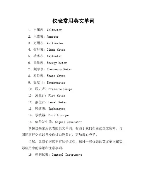
仪表常用英文单词1. 电压表:Voltmeter2. 电流表:Ammeter3. 万用表:Multimeter4. 钳形表:Clamp Meter5. 功率表:Wattmeter6. 能量表:Energy Meter7. 频率表:Frequency Meter8. 相位表:Phase Meter9. 温度计:Thermometer10. 压力表:Pressure Gauge11. 流量计:Flow Meter12. 液位计:Level Meter13. 转速表:Tachometer14. 示波器:Oscilloscope15. 信号发生器:Signal Generator掌握这些常用仪表的英文单词,有助于我们在阅读英文资料、与国际同行交流以及操作进口设备时,更加得心应手。
当然,让我们继续丰富这份文档,探讨一些仪表的英文单词在实际应用中的场景和注意事项。
16. 控制仪表:Control Instrument在自动化控制系统中,控制仪表起着至关重要的作用。
它们可以是对温度、压力、流量等进行精确控制的设备,如PID控制器(PID Controller)。
17. 分析仪表:Analytical Instrument用于化学、生物等领域,分析仪表能够对样品进行成分分析,如气相色谱仪(Gas Chromatograph)和质谱仪(Mass Spectrometer)。
18. 调节阀:Control Valve调节阀用于调节流体介质的流量、压力等参数,是工业流程控制中的关键组件。
19. 传感器:Sensor传感器是将各种物理量转换为电信号的装置,如温度传感器(Temperature Sensor)、压力传感器(Pressure Sensor)等。
20. 变送器:Transmitter变送器通常与传感器配合使用,将传感器的信号转换为标准信号输出,如420mA电流信号,用于远距离传输。
21. 显示仪表:Display Instrument显示仪表用于直观地显示各种测量数据,如数字显示表(Digital Display Meter)和模拟显示表(Analog Display Meter)。
仪器仪表常用英语词汇pH计 pH meterX射线衍射仪 X-ray diffractometerX射线荧光光谱仪 X-ray fluorescence spectrometer力测量仪表 force measuring instrument孔板 orifice plate文丘里管 venturi tube水表 water meter加速度仪 accelerometer可编程序控制器 programmable controller平衡机 balancing machine皮托管 Pitot tube皮带秤 belt weigher光线示波器 light beam oscillograph光学高温计 optical pyrometer光学显微镜 optical microscope光谱仪器 optical spectrum instrument吊车秤 crane weigher地中衡 platform weigher字符图形显示器 character and graphic display位移测量仪表 displacement measuring instrument巡迴检测装置 data logger波纹管 bellows长度测量工具 dimensional measuring instrument长度传感器 linear transducer厚度计 thickness gauge差热分析仪 differential thermal analyzer扇形磁场质谱计 sector magnetic field mass spectrometer 料斗秤 hopper weigher核磁共振波谱仪 nuclear magnetic resonance spectrometer 气相色谱仪 gas chromatograph浮球调节阀 float adjusting valve真空计 vacuum gauge动圈仪表 moving-coil instrument基地式调节仪表 local-mounted controller密度计 densitometer液位计 liquid level meter组装式仪表 package system减压阀 pressure reducing valve测功器 dynamometer紫外和可见光分光光度计 ultraviolet-visible spectrometer 顺序控制器 sequence controller微处理器 microprocessor温度调节仪表 temperature controller煤气表 gas meter节流阀 throttle valve电子自动平衡仪表 electronic self-balance instrument电子秤 electronic weigher电子微探针 electron microprobe电子显微镜 electron microscope弹簧管 bourdon tube数字式显示仪表 digital display instrument热流计 heat-flow meter热量计 heat flux meter热电阻 resistance temperature热电偶 thermocouple膜片和膜盒 diaphragm and diaphragm capsule调节阀 regulating valve噪声计 noise meter应变仪 strain measuring instrument湿度计 hygrometer声级计 sound lever meter黏度计 viscosimeter转矩测量仪表 torque measuring instrument转速测量仪表 tachometer露点仪 dew-point meter变送器 transmitter仪器仪表常用术语性能特性 performance characteristic确定仪器仪表功能和能力的有关参数及其定量的表述。
Multifunctional applications to several tablesOn the rotational speed table design has many available, but mostly by mechanical or simulated digital circuits to achieve.there are large in size,precision low,not visual,electronics large, less functional and sampling time,it is difficult to detect instantaneous rotational speed. as Chanpianji with both small and control functions such strong characteristics,so it widely in control applications.we want multifunctional rotational speed control system is designed to shanpianji as the core to achieve intelligent meters. It is more functional,small electronics,and visual accuracy,showing time,speed warning systems,printing,such as instant rotational speed advantage.in computer hardware and software technology development efforts, and to present such functional single,low precision,size and price of high rotational speed tables are upgrading equipment.currently rotational speed table as a common measurement tool has many coming to market,such as:mechanical,electrical anmech- anical style, electromagnetic-type, photoelectric type.although they are precise Measurements,the use of safe,operate,but the prevailing question is a single function In the current hardware and software to improve the precision and functions on the Basis of achieving a comprehensive equipment upgrading and improving pilot skills. The introduction of new technology developed multifunctional rotational speed table, With general rotational speed table functions,but also with other special functions. From the 1970s, the human acrospace ,transport and weapons industry problems Encountered difficulty in the traditional theory to solve. The need to promote the Development of the productive forces in computer systems technology to develop. Accompanied by computer hardware and software rapid development of technology, Master degrees in multifunctional rotational speed table,function ,performance,and Have a rapid development architecture,has been able to master a complete powerful, Performance quality laser systems. Now Europe and the United States and other Developed countries,laser system technology has been successfully applied to Acrospace ,transportation,ordnance industry,mechanical design,and many other areas, Has atremendous benefit,but also for traditional design testing methods have changed Dramatically. this is the modern market demand for products that do not , how to Improve the success rate of the initial design of the traditional design methodology is a Difficult question.because of its high Chanpianji master degrees,both small and anti- Interference capability and affordable, unique control functions,it has become an im- Portant member of the computer world,applications in one ,only one chanpianji,which Is currently the largest application form,the main application areas are: (1). Monitoring system .shanpianji may constitute a variety of industrial control systems,adaptive systems,data acquisition systems(2).monitoring system.shanpianji may constitute a variety of industrial controlSystem,adaptive systems,data acquisition systems.(3).and integration products.shanpianji combination with the traditional mechanicalProducts,mechanical products simplify system control intelligent.(4).smart interface .in the computer control system(especially the larger industrialMonitoring and control systems),widespread adoption danpianji interface for the Control and management of the mainframe is chanpianji parallel with the work,it hasGreatly enhanced system operating speed.However shanpianji application must not be limited to its broad meaning and scope of The economic benefits arising from,more important lies in: danpianji applications are Fundementally changing the traditional collection control system design concepts and Design methods. Former circuit or digital circuit must be similated toachieve most of The control functions can now be used shanpianji through software (programming) Methods achieved.to replace hardware and software that can control technology will Enhance system performance with danpianji popularize the application of constantDevelopment and improvement.Shanpian microcomputers for the emergence of automated instrumentation opens broad Prospects. mcs-sj-chanpian particular type of performance computer, size, energy, Advantages,and strong computing,processing and memory storage capabilities to Control components uesd danpianji wisdom meters into the upgrading of industrial Products and advanced technology are economic means.maintain a peak capacity.Rotational speed changes to the "memory of the greatest rotational speed values.a "black box function.to the permanent preservation of important rotational speed data.For accident analysis,review appliacations,normal circumstances can provide data Analysis.amendment can be preserved to the different requirements of printintervals .thereby speeding access to test data,a maximum speed of data.anti-interference capability.on the important of abroader range of adaptive signal.applicable to electromagnetic type,photoelectric type fluid style,and many other sensors to produce one pulse per or 60-(60)business,the meters particularly suited to the testing plant housing units rotational speed,control,similar to other mining industry uses also apply.meters into measurement.display,interactive,and print several of thepolice.smart devices are microprocessors at the core of electronic equipment,hardware circuit design of the components to the mastery of the principles of work,but also for its masteryof micro-computer hardware principles.the general wisdom equipment design steps: first, it is necessary to determine the design of the mission,to prepare the design task sheets,equipment should have clear functions and should meet the technical requirements,design of mission statement is the basis for the design designers should strive to accurate precision;and then to design programmers to develop,at this stage,designers must make several designoptions,each programme should include equipment design principles, using the technology,the key components of performance :then to conduct a feasibility study on the programme. including some important part of theoretical analysis and calculation,and the necessary simulation experiments,in order to achieve certification programme can design requirements;then again into one of the options as a factor in the design of programmes to identify machines work equipment total diagram;finally, the hardware circuit and software debugging and circuit design and the overall tone. software components.which mainly 89C52 chanpianji hardware circuits,laser converters,keyboard set threshold,warning circuit,and the led LCD system with the computer interface circuits.software components including control procedures.These monitoring procedures for equipment panels keyboards and monitors,and its contents include:import and storage through keyboard operation established by the functional, operational modalities and activities of parameters;through data collection control I/O interface circuits for equipment intended for installation; ROM of the data recorded data and various state; to figures,characters, graphic,and other forms of state information and measurements show that the out of the process.多功能转速表的应用关于转速表的设计已经有很多可供参考,但大部分都是由机械式或模拟数字电路来实现的。
浙江师范大学本科毕业设计(论文)外文翻译1本科毕业设计(论文)外文翻译家庭的低数CISC的8051 各种组件的功能如下所述。
微型控制器。
由于它的与基于微型控制器使用20引脚的AT89C2051字计算、支付能力和兼容性从Atmel 的一个1282 KB的闪存,这里。
所有的微控制器引脚可利用的项目。
这个微型控制器具有位定时器或者计数器、一个线、两个16输入/输出)-个字节RAM,15条输入输出(、一个全双工串行口、一个高精确度模拟比较器、一片上振荡向量两级中断结构,5 器和时钟电路。
字16x2液晶显示模块。
要显示移动的速度和距离,我们使用一块基于HD44780的的引脚LCD母数字液晶控制器。
LCD的背光功能,使数据即使在夜晚都依然可见。
配置和液晶显示功能。
早前已经被发表在液晶显示器有EFY的几个问题中。
中。
在这里使用距离行驶的读数都保存在一个外部串行EEPROM。
串行EEPROM EEPROM。
的是24C02飞利浦协议的串行)和SDA总线协议。
该总线由两个活动连接线和一条地线。
主动线,串行数据线()是双向的。
挂接到总线的每个设备都有自己唯一的地址,不管SCL 串行时钟线(。
根据功能,这些芯片都可以作为一个驱动器,内存或ASICLCD 它是一个MCU,芯片可以驱动器只是一个接收器,而记忆体或/或发射机。
显然,LCDI/O接收器和发起数据传同时发射器和接收器。
该总线是一种多主总线。
这意味着,超过一个IC,它被认为是上启动主机总线的数据传输能力可以连接到它。
该协议规范规定的IC 2本科毕业设计(论文)外文翻译本科毕业设计(论文)外文翻译.2图制造建设中的簧片开关和磁铁需要在电机的自行车(英雄本田的辉煌)前轮固定。
通常在使用扬声器的小玩具中是都可以用到的。
,一个小的圆形磁铁(直径约2厘米)磁铁固定在鼓的中部连接到下方的辐条轮鼓。
磁铁固定使用热胶水或环氧树脂。
固管的机械需要,需要使磁铁和干簧管正确对齐,如图.3所示。
PVC定磁簧开关,管测量垂直剪下,分为两半。
只用一个一半PVC15.2将3.2厘米直径、长厘米管。
坐骑和安全保障的的干簧管和电缆用领带固定在熟料手柄上(通常用于的PVC。
一旦烘干,焊两条线的另一端当两个簧片开关的引线。
塑料手柄上紧急照明设备)用螺钉固定。
现在,请将前面避震前叉,使得磁簧开关管正对磁体的开关。
4本科毕业设计(论文)外文翻译.3图慢慢转动方向连接万用表,将它设置在连续性模式下,两条电线来字磁簧开关。
盘,当磁铁横跨它通过时,看看簧片开关是否关闭。
如果是这样的话,万用表会提供连续性的响声。
当磁铁移开远离磁簧开关后,蜂鸣声将停止,这表明该簧片开关管,让磁簧开关顺畅工作的处于打开状态。
做一些试验,以找到安装和固定的PVC管玩意儿的减震器前最佳位置。
马克前面减震器叉的位置。
现在您可以修复的PVC。
使用一定的热胶,以确保管道的自由。
仔细检查自行车的叉采用热胶,如图所示.5车把上的两条电线之间的关系,以确保能顺利使用电缆线,这就完成了传感器安装的一部分。
主电路和液晶显示模块可安装在合适的塑料外壳中,可随时在电子商店中买到。
这些外壳应具有易于安装的液晶面板预切槽。
如果这样的框不可用,您可以使用适当取消对某些部分的液晶面板的电子电抗器的塑料盒。
电源可采取直接从的电池或挖掘控制台的大灯开关和指示灯。
为此,您需要拆卸交换机自行车的12V控制台并积极用万用表识别正面导线和接地导线。
在进行这一步时,记住要关闭点厘米两芯线连接到交换机控制台内的正负极。
必须采取从交换机控制台60火。
钎具提供,它的优点是点火钥匙的控制,而主要单位是无需单独的通断开关电源。
一个实际的尺寸,单面印刷电路板的基于微控制器的速度表暨里程表布局如图所示。
在。
.7和元件布局图.8图测试文件放置在一个微上,方案与Init_EEPROM.hex当所有的部件测试被焊在PCB,行一在电路。
LCD的第关的相片器控脚20器控制和引微制芯和应开显示在第二行。
这个过程将删除任何以出现。
五秒钟后,‘INIT_EEPROM'‘00000 .0'的主现在关掉电源和EEPROM前的数据并且将中的初始读数调整为零。
'speedo.hex 5本科毕业设计(论文)外文翻译会显LCD编程后,单片机电路和开关电源回到先前的状态。
要文件中的微控制器。
在第二行。
现在,先准备你要测小时:/00.0在第一行,'速度千米公里:示‘00000.0试的车子。
连接两条电线从干簧管和电源线来的主要单位。
装载在自行车的车把中的夹子用于固定手柄的机箱顶部单位。
您可以使用电缆来做到这一点。
安装心的'u'。
现在来做个测试,启动自行车,如果连接是正确的,速度和距离布置的位置如图.6 将在液晶显示屏上显示出来。
像聚乙烯防护罩可用于雨天的主机使用。
CD中。
的注意。
本文的源代码已被列入thismonthEFY –EFY.4图.5图 6本科毕业设计(论文)外文翻译.6图.7图.8 图7本科毕业设计(论文)外文翻译8本科毕业设计(论文)外文翻译Fig. 1.are of the microcontroller family. CISC-based 8051 All the available pins and compatibility with utilised in the project. This microcontroller features 2 kB of Flash, 128 bytes of RAM, 15 input/output (I/O) lines, two 16-bit timers/counters, a five-vector two level interrupt architecture, a full-duplex serial port, a precision analogue comparator, on-chip oscillator and clock circuitry.module. LCD To display the speed and distance traveled, we have used a 16x2 alphanumeric LCDbased on HD44780 controller. The backlight feature of the LCD allows data to be visible even at night. .The pin configuration and features of this LCD have earlier been published in several issues ofEFY Serial EEPROM. The readings of the distance traveled are saved in an external serial EEPROM.2 C protocol is used.Here, a 24C02 serial EEPROM based on Philips I2protocol. C Ibus 2activeThe wires and a ground IThe connection. C bus consists of two activewires, serial data line (SDA) and serial clock line (SCL) are bidirectional.Every device hooked up to the bus has its own unique address, no matter whether it is an MCU,LCD driver, memory or ASIC. Each of these chips can act as a receiver and/or transmitter, depending on the functionality. Obviously, an LCD driver is only a receiver, while a memory or I/O chip can be both transmitter and receiver.2C bus is a multi-master bus. This means that more than one IC capable of initiating a data The I2data initiates IC that a that it. be connected to The IC protocol specification states the can transfer microcontrollers. masters are generally Bus bus considered bus on transfer the is the master. Consequently, all the other ICs are regarded as bus slaves at that instant.Let's assume that the MCU wants to send data to one of its slaves. First, the MCU will issue ahe busSTART condition. This acts as an ‘attention' signal to all of the connected devices. All ICs on t 9本科毕业设计(论文)外文翻译10本科毕业设计(论文)外文翻译Fig. 2.Construction(Hero bike of the motor wheel magnet a need to be fixed on the front reed The switch andre), normally used in speakers of Honda's Splendor). A small circular magnet (about 2 cm in diametspokes the below drum of the wheel just to used. small toys, can be Fix the magnet the central connected to the drum. Secure the magnet using hot glue or Araldite.For fixing the reed switch, a PVC pipe contraption needs to be made so that the magnet and reed switch are aligned as shown in Fig. 3. The materials required to build the contraption are shown in Fig.4. Cut a 3.2cm diameter PVC pipe measuring 15.2 cm in length perpendicularly into two halves. Use only one half of the PVC pipe. Mount and secure the reed switch using Araldite and cable ties on the two wires to the two up, it lights). in (normally plastic handle used emergency Once dries solder opposite end leads of the reed switch. Fix the plastic handle on the half cut PVC pipe using screws. Now, place the pipe on the front shock-absorber fork such that reed switch faces towards the magnet. Connect a multimeter, set in continuity mode, to the two wires coming from the reed switch. Rotate the11本科毕业设计(论文)外文翻译Fig. 3.Fig. 4.wheel slowly and see whether the reed switch closes when the magnet passes across it. If it does, the multimeter will give a continuity beep. When the magnet moves away from the reed switch, the beep for position to a few trials find the optimal Make is reed that stop, will indicating the switch open. mounting and fixing the PVC pipe such that the reed switch works smoothly. Mark the location on the front shock-absorber fork.Now you can fix the PVC pipe contraption to the shock-absorber fork using hot glue as shown in Fig. 5. Use liberal amount of hot glue to secure it to the pipe. Carefully route the two wires up to the unting part.bike's handle bar using cable ties to secure the wire. This completes the sensor mo12本科毕业设计(论文)外文翻译Fig. 5.are plastic enclosures, which module can be housed in suitable The main circuit and the LCDeasy slot for These enclosures should have precut readily available in electronic projects shops. mounting of the LCD panel. If such boxes are not available, you can use the plastic boxes of electronic chokes by suitably removingsupply can be taken either directly from the bike's 12V Some portions for the LCD panel. Power battery or tapped from the console which houses horn, headlight and indicator light switches. For this, you need to remove the switch console and identify positive wire and ground wire using a multimeter. -core When carrying out this step, remember to turn the ignition key to‘on' position. Solder a 60cm twowire to the positive and negative terminals inside the switch console. The advantage of taking supplywithout the main unit controls ignition key the power supply to that the from switch console is the having a separate on-off switch.the layout of An actual-size, single-side PCBis microcontroller-based speedometer-cum-odometershown in Fig. 7 and its component layout in Fig. 8.Fig. 8.13本科毕业设计(论文)外文翻译Fig. 6Fig. 7Testingwith the microcontroller the the components are soldered on PCB, program After allInit_EEPROM.hex file and place the microcontroller in a 20-pin IC base and switch on the circuit.In the first line of the LCD, ‘INIT_EEPROM' appears. After five seconds, ‘00000.0' is displayed in the second line. This process erases any previous data and sets the initial readings in the EEPROM to zero. Now switch off the supply and program the microcontroller with ‘speedo.hex' main file. After will supply. The LCD the the the programming, place microcontroller back in circuit and switch onis the line. the 00.0' and first in ‘Kms: show 00000.0' the line ‘SpeedKms/Hr: in second Now, unit ready to mount on your bike.14本科毕业设计(论文)外文翻译15。