键盘接口
- 格式:ppt
- 大小:637.00 KB
- 文档页数:40


键盘接口出现故障怎么办键盘接口内部的弹性接触片由于长时间的使用或者是经常性的弯曲拉动,有时候就会出现扩张现象,从而也就导致了键盘插头的针跟接口中的弹性接触片接触不良或者是没法接触。
一起来看看键盘接口出现故障怎么办,欢迎查阅!键盘的常见故障及处理方法一、键盘的个别按键不能输入这个时候计算机启动时自检正常,但启动后,大多数按键是可以正常输入,有个别的按键不能输入。
这种情况说明键盘上的电路、主机键盘控制接口是正常工作的。
个别按键不能输入的原因可能是该按键座内的弹片失效或者是键内被灰尘污染。
这个时候只要打开键盘,用干的毛巾擦擦按键与金属接触的地方,如果弹片损坏,就小心的拨正它,实在不行就换一个就可以了。
二、按键输入的不是想要的信息当正常启动机器后,在输入框中输入某个按键的字符时时,显示出来的并不是本位按键上的字符,而显示其它键位的字符。
这种情况大多数按键是正常,有几个键位输入时不显示键位本身的字符,而显示其它按键位的字符,一般是按键的连线松动或脱落,造成按键码串位所致。
解决这种情况只要打开键盘,查看键位连接线,查出故障位置,调整正确后,然后拧紧螺丝就可以了。
三、键盘的灰尘清理使用久了,无论是键盘表面还是键盘的内部,都可能积满了灰尘。
这个时候怎么清理呢。
可以把键盘反过来轻轻拍打,让其内的灰尘落出;也可以用湿布清洗键盘表面,但注意湿布一定要拧干,以防水进入键盘内部。
使用时间较长的键盘需要拆开进行维护。
拆卸键盘比较简单,拔下按键盘与主机连接的电缆插头,然后把键盘正面向下放到桌子上,卸下底板上的螺钉,即可取下按键盘后盖板。
如果是清理键盘的内部,一定记着不要用水来清洗,因为水很容易腐蚀按键盘里面的金属。
可以用酒精清洗。
也可以可以用油漆刷或者油画笔扫除电路板和键盘按按键上的灰尘。
四、键盘接口损坏有些时候,键盘的接口损坏,怎么输入也不管用。
这种情况,就要把按键盘拆开。
把按键帽取下,滴入酒精,装上按键帽,反复敲击几次。
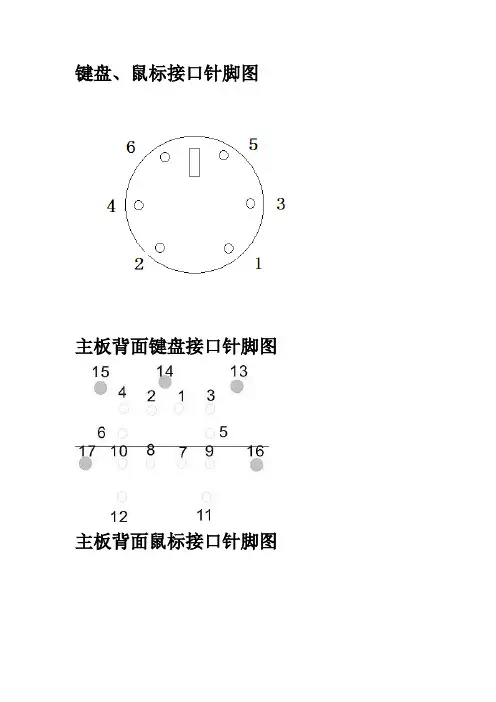
键盘、鼠标接口针脚图
主板背面键盘接口针脚图
主板背面鼠标接口针脚图
键盘、鼠标接口的各针脚功能
时钟脚(CLOCK)同步,并通过数据脚(DA TA)交换数据。
主板中键盘、鼠标的接口电路主要由PS/2接口、电容、电感、排阻、跳线、南桥芯片或I/O芯片等组成,主板键盘、鼠标接口电路的时钟信号和数据信号一般由南桥或I/O芯片控制。
检测键盘/鼠标接口时,可以测量以下关键测试点
1、测量键盘、鼠标接口的供电引脚(第4脚)对地阻值,正常阻
值应为180~380Ω。
2、测量键盘、鼠标接口的数据线(第1脚)和时钟脚(第5脚)
的对地阻值,正常阻值应为600Ω左右。

电脑键盘接线图判断键盘控制电路板上的四根线各起什么作用至关重要。
将电路板翻过来后可以看到其背面已有明确的提示(图四):黄线Vcc为+5V高电平;红线为地线GND低电平;绿线为Keyboard DATA高电平;白线为Keyboard Clock低电平。
不同的键盘连线颜色的定义可能也不同,因此如果不能根据提示正确识别的话可以用万用表测量一下或者参考图五中对于连线的定义(图五)。
USB延长线中也是一组四根线,分别为红、白、绿、黑四根。
它们分别对应的是+5V电源、数据负线(DATA-)、数据正线(DATA+)及地线(GND)电脑键盘的四根线如何接罗技键盘,y-ss60线的颜色:红,绿,白,黑盼请解答,谢谢!四根线分别是:电源,地,数据,时钟你要把键盘拆出来,线的另一端焊在里面的电路板,上面标有v(电源),g(地),c(时钟),d(数据).再到网上找个键盘接口定义的图,对着另一端接上去就可以了这是普通的ps/2的键盘接线图,图中是接口(ps/2插头)截面图。
上面标的字母一般在键盘里的电路板上有印的,对照着焊就行了。
如果没有标注字母,这个我就没办法了哈哈~多数键盘应该是按照dcgv的顺序排线的,没有写明的可优先考虑这个。
针脚定义如下:pinnamedirdescription1n/cnotconnected2data-keydata3vccpower,+5vdc4gndgnd5n/cnotconnected6clk-clock键盘接线黄、红、白、绿对应的针脚如下对应ps/2线对应ps/2针脚黄3红4白6绿2对应的电线和针脚连接为:对应ps/2线对应ps/2针脚蓝3白6绿2橙4PS/2鼠标自己动手改USB接口USB作为电脑外设的一种高速连接标准,目前已广泛应用到了各种外部设备上。
电脑主机则在机箱上提供了前置USB接口,有的厂商甚至是在显示器与键盘都添加了USB接口,其目的就是为了能够让用户方便的进行连接鼠标、数码相机等耗电量小的USB外设而无须费力弯腰去机箱背后接插USB设备。

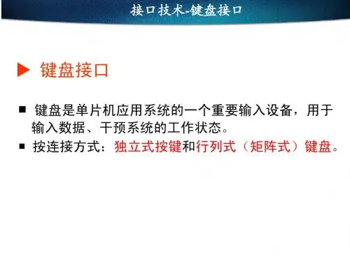
常用键盘接口
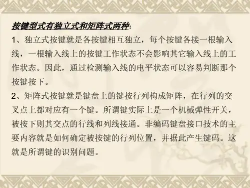
常用按键接口可分为独立式按键接口、行列式按键接口和专用芯片式等。
具体采用哪种方式,可根据所设计系统的实际情况而定。
下面分别介绍这几种接口方式的优缺点及适用场合。
1.独立式按键接口
独立式按键接口设计优点是电路配置灵活,软件实现简单。
但缺点也很明显,每个按键需要占用一根口线,若按键数量较多,资源浪费将比较严重,电路结构也变得复杂。
因此本方法主要用于按键较少或对操作速度要求较高的场合。
软件实现时,可以采用中断方式,也可以采用查询方式,示意图如图所示。
图独立式键盘接口
2.行列式按键接口
行列式按键接口示意图如图(a)所示,其使用原理将在下节详细讲述。
行列式按键接口适应于按键数量较多,又不想使用专用键盘芯片的场合。
这种方式的按键接口由行线和列线组成,按键位于行、列的交叉点上。
这种方式的优点就是相对于独立接口方式可以节省很多I/O 资源,相对于专用芯片键盘可以节省成本,且更为灵活。
缺点就是需要用软件处理消抖、重键等。
行列式按键接口是一种老式的键盘接口,其键扫描方法是几乎所有PC 键盘所采用的方法。
tips:感谢大家的阅读,本文由我司收集整编。
仅供参阅!。
IBM Keyboards. Not really an interesting topic, one would expect. So why would you want to interface the Keyboard? The IBM keyboard can be a cheap alternative to a keyboard on aMicroprocessor development system. Or maybe you want a remote terminal, just couple it with a LCD Module.Maybe you have a RS-232 Barcode Scanner or other input devices, which you want to use with existing software which only allows you to key in numbers or letters. You could design yourself a little box to convert RS-232 into a Keyboard Transmission, making it transparent to the software.An interfacing example is given showing the keyboard's protocols in action. This interfacingexample uses a 68HC705J1A MCU to decode an IBM AT keyboard and output the ASCIIequivalent of the key pressed at 9600 BPS.Note that this page only deals with AT Keyboards. If you have any XT keyboards, you wish to interface, consider placing them in a museum. We will not deal with this type of keyboard in this document. XT Keyboards use a different protocol compared to the AT, thus code contained on this page will be incompatible.The IBM keyboard you most probably have sitting in front of you, sends scan codes to yourcomputer. The scan codes tell your Keyboard Bios, what keys you have pressed or released.Take for example the 'A' Key. The 'A' key has a scan code of 1C (hex). When you press the 'A' key, your keyboard will send 1C down it's serial line. If you are still holding it down, for longer than it's typematic delay, another 1C will be sent. This keeps occurring until another key has been pressed, or if the 'A' key has been released.However your keyboard will also send another code when the key has been released. Take the example of the 'A' key again, when released, the keyboard will send F0 (hex) to tell you that the key with the proceeding scan code has been released. It will then send 1C, so you know which key has been released.Your keyboard only has one code for each key. It doesn't care it the shift key has been pressed. It will still send you the same code. It's up to your keyboard BIOS to determine this and take the appropriate action. Your keyboard doesn't even process the Num Lock, Caps Lock and Scroll Lock. When you press the Caps Lock for example, the keyboard will send the scan code for the cap locks. It is then up to your keyboard BIOS to send a code to the keyboard to turn on the Caps lock LED.Now there's 101 keys and 8 bits make 256 different combinations, thus you only need to send one byte per key, right?Nop. Unfortunately a handful of the keys found on your keyboard are extended keys, and thus require two scan code. These keys are preceded by a E0 (hex). But it doesn't stop at two scan codes either. How about E1,14,77,E1,F0,14,F0,77! Now that can't be a valid scan code? Wrong again. It's happens to be sent when you press the Pause/break key. Don't ask me why they have to make it so long! Maybe they were having a bad day or something?When an extended key has been released, it would be expect that F0 would be sent to tell you that a key has been released. Then you would expect E0, telling you it was an extended key followed by the scan code for the key pressed. However this is not the case. E0 is sent first, followed by F0, when an extended key has been released.Besides Scan codes, commands can also be sent to and from the keyboard. The following section details the function of these commands. By no means is this a complete list. These are only some of the more common commands.These commands are sent by the Host to the Keyboard. The most common commandwould be the setting/resetting of the Status Indicators (i.e. the Num lock, Caps Lock &Scroll Lock LEDs). The more common and useful commands are shown below.ED Set Status LED's - This command can be used to turn on and off theNum Lock, Caps Lock & Scroll Lock LED's. After Sending ED, keyboardwill reply with ACK (FA) and wait for another byte which determines theirStatus. Bit 0 controls the Scroll Lock, Bit 1 the Num Lock and Bit 2 theCaps lock. Bits 3 to 7 are ignored.EE Echo - Upon sending a Echo command to the Keyboard, the keyboardshould reply with a Echo (EE)F0Set Scan Code Set. Upon Sending F0, keyboard will reply with ACK(FA) and wait for another byte, 01-03 which determines the Scan CodeUsed. Sending 00 as the second byte will return the Scan Code Setcurrently in UseF3Set Typematic Repeat Rate. Keyboard will Acknowledge command withFA and wait for second byte, which determines the Typematic RepeatRate.F4Keyboard Enable - Clears the keyboards output buffer, enablesKeyboard Scanning and returns an Acknowledgment.F5Keyboard Disable - Resets the keyboard, disables Keyboard Scanningand returns an Acknowledgment.FE Resend - Upon receipt of the resend command the keyboard will re-transmit the last byte sent.FF Reset - Resets the Keyboard.Now if the Host Commands are send from the host to the keyboard, then the keyboardcommands must be sent from the keyboard to host. If you think this way, you must becorrect. Below details some of the commands which the keyboard can send.FA AcknowledgeAA Power On Self Test Passed (BAT Completed)EE See Echo Command (Host Commands)FE Resend - Upon receipt of the resend command the Host should re-transmit the last byte sent.00Error or Buffer OverflowFF Error or Buffer OverflowThe diagram below shows the Scan Code assigned to the individual keys. The Scan code is shown on the bottom of the key. E.g. The Scan Code for ESC is 76. All the scan codes are shown in Hex.As you can see, the scan code assignments are quite random. In many cases the easiest way to convert the scan code to ASCII would be to use a look up table. Below is the scan codes for the extended keyboard & Numeric keypad.The PC's AT Keyboard is connected to external equipment using four wires. These wires are shown below for the Male Plug.The Host to Keyboard Protocol is initiated by taking the KBD data line low. However to prevent the keyboard from sending data at the same time that you attempt to send the keyboard data, it is common to take the KBD Clock line low for more than 60us. This is more than one bit length.Then the KBD data line is taken low, while the KBD clock line is released.The keyboard will start generating a clock signal on it's KBD clock line. This process can take up to 10mS. After the first falling edge has been detected, you can load the first data bit on the KBD Data line. This bit will be read into the keyboard on the next falling edge, after which you can place the next bit of data. This process is repeated for the 8 data bits. After the data bits come an Odd Parity Bit.Once the Parity Bit has been sent and the KBD Data Line is in a idle (High) state for the next clock cycle, the keyboard will acknowledge the reception of the new data. The keyboard does this by taking the KBD Data line low for the next clock transition. If the KBD Data line is not idle after the 10th bit (Start, 8 Data bits + Parity), the keyboard will continue to send a KBD Clock signal until the KBD Data line becomes idle.Normally in this series of web pages, we connect something to the PC, to demonstrate theprotocols at work. However this poses a problem with the keyboard. What could be possibly want to send to the computer via the keyboard interface?Straight away any devious minds would be going, why not a little box, which generatespasswords!. It could keep sending characters to the computer until it finds the right sequence.Well I'm not going to encourage what could possibly be illegal practices.In fact a reasonably useful example will be given using a 68HC705J1A single chip microcontroller.We will get it to read the data from the keyboard, convert the scan codes into ASCII and send it out in RS-232 format at 9600 BPS. However we won't stop here, you will want to see the bi-directional use of the KBD Clock & Data lines, thus we will use the keyboards status LEDS, Num Lock, Caps Lock and Scroll Lock.This can be used for quite a wide range of things. Teamed up with a reasonably sized 4 line x 40 character LCD panel, you could have yourself a little portable terminal. Or you could use it with a microcontroller development system. The 68HC705J1A in a One Time Programmable (OTP) is only a fraction of the cost of a 74C922 keyboard decoder chip, which only decodes a 4 x 4 matrix keypad to binary.The keyboard doesn't need to be expensive either. Most people have many old keyboards floating around the place. If it's an AT Keyboard, then use it (XT keyboards will not work with thisprogram.) If we ever see the introduction of USB keyboards, then there could be many redundant AT keyboards just waiting for you to hook them up.! "Before we start with the technical aspects of the project, the salesman in me wants to tell you about the features packed into the 998 bytes of code.Use of the keyboard's bi-directional protocol allowing the status of the Num Lock, Caps Lock and Scroll Lock to be displayed on the Keyboards LEDs.External Reset Line activated by ALT-CTRL-DEL. If you are using it with a Microcontroler development system, you can reset the MCU with the keyboard. I'vealways wanted to be able to use the three fingered solute on the HC11!Scroll Lock and Num Lock toggles two Parallel Port Pins on the HC705. This can be used to turn things on or off, Select Memory Pages, Operating Systems etc "ALTDEC" or what I call the Direct Decimal Enter Routine. Just like using a PC, when you enter a decimal number when holding down one of the ALT keys the number issent as binary to the target system. E.g. If you press and hold down ALT, then type in255 and release ALT, the value FF (Hex) will be sent to the system. Note. Unlike thePC, you can use both the numeric keypad or the numbers along the top of thekeyboard."CTRLHEX" or you guessed it, Direct Hexadecimal Enter Routine. This function is not found with the PC. If you hold CTRL down, you can enter a Hexadecimal number. Justthe thing for Development Systems or even debugging RS-232 Comms?Output is in ASCII using a RS-232 format at 9600 BPS. If using it with a development System, you can tap it in after the RS-232 Line Transceivers to save you a few dollarson RS-232 Level Converters.# $The schematic below, shows the general connections of the keyboard to the HC705. The O.C.on the inverters denotes Open Collector outputs. I've used 74LS05 for the Open Collector Inverters, but it is up to you how you want to implement it. You can also use transistors with a suitable current limiting resistor, if you see fit.The TXD pin, while it transmits in RS-232 format, is not at RS-232 Voltage Levels. If you want to connect it to RS-232 Devices then you will need to attach a RS-232 Level Converter of some kind. If you are using it with a development system, you can bypass both RS-232 Level Converters and connect it directly to the RXD pin of the MCU. However the keyboard can't be a direct replacement for a terminal on a development system, unless you want to type in your code each time! You may want to place a jumper or switch inline to switch between your RS-232 Port and the keyboard.The circuit is designed to run on a 4Mhz crystal (2Mhz Bus Speed). The timing for the RS-232 transmission is based on the bus speed, thus this crystal has to be 4 Mhz. If you are lucky enough to have a 4 Mhz E Clock on your development system you can use it. I might at a later date try to create a 2 Mhz version which will run happily off a HC11 with a 8 Meg Crystal. This will reduce the cost of the project even further.The power supply can also create a slight problem. A standard keyboard can drain about300mA max, thus it would be recommended to use it's own regulator rather than taking a supply from elsewhere. Filter Capacitors are not shown on the general schematic but are implied for reliable operation. Consult your MC68HC705J1A Technical Data Manual for more information.% & 'Now it is time to look at the code. I cannot include a description of all the code in this web page. The list file is just on 16 pages. Most of it (hopefully) is easy to follow. Just like other code, count the number of spelling errors, while you are at it.Receive ldx #08 ;Number of Bitsclra ;Clear Parity Registerbclr clkout,PORTB ;Clear to Sendbrset clkin,PORTB,* ;wait for idle Clockbrset datain,PORTB,Receive ;False Start Bit, RestartRemember the KBD Clock line? If you take it low, the keyboard will buffer any keys pressed. The Keyboard will only attempt to send when both the Data and Clock lines are idle (high). As it can take considerable time to decode the keys pressed, we must stop the keyboard from sending data. If not, some of the data may be lost or corrupted.The program, will keep the KBD Clock line low, unless it is ready to accept data. We will use a loop to retrieve the data bits from the keyboard, thus we will load index register X with the number of bits be want to receive. The Accumulator will be used to verify the parity bit. We must clear this first.We then place the KBD Clock line in the idle state so that the keyboard will start transmitting data if a key has been pressed. The program then loops while the Clock Line is Idle. One the KBD clock goes low, the loop is broken and the KBD Data Line is read. This should be the start bit which should be low. If not we branch to the start of the receive routine.Recdata ror bytejsr highlow ;Wait for high to low Transitionbrset datain,PORTB,Recsetbclr 7,bytejmp RecnextRecset bset 7,byteincaRecnext decxbne Recdata ;Loop until 8 bits been receivedOnce the Start bit has been detected, the 8 data bits must follow. The data is only valid on the falling edge of the clock. The subroutine highlow shown below will wait for the falling edge of the clock.highlow brclr clkin,PORTB,* ;Loop until Clk Highbrset clkin,PORTB,* ;Loop until Clk LowrtsAfter the falling edge we read the level of the KBD Data line. If it is high we set the MSB of byte or if it is clear, we clear it. You will notice if the bit is set, we also increment the accumulator. This keeps track of the number of 1's in the byte and thus can be used to verify the Parity Bit. Index register X is decremented as we have read a byte. It then repeats the above process, until the entire 8 bits have been read.jsr highloweor PORTB ;Parity Bit Detectionand #$01beq r_errorAfter the 8 data bits, comes the dreaded Parity Bit. We could ignore it if we wanted to, but we may as well do something about it. We have been keeping a tally of the number of 1's in the Accumulator. The keyboard uses Odd parity, thus the parity bit should be the complement of the LSBit in the Accumulator. By exclusive OR-ing the Accumulator with the Parity Bit, we get a 1 if both the bits are different. I.e a '1' if the parity bit checks out.As we are only interested in the LSB we can quite happy XOR the accumulator with PORTB. However this means the KBD datain must be connected to PB0. This can be a slight catch if you alter the equates. Then we single out the LSB using the AND function. If the resultant is zero, then a parity error has occurred and the program branches to r_error.jsr highlowbrclr datain,PORTB,r_error ;Stop Bit Detectionbset clkout,PORTB ;Prevent Keyboard from sending data;(Clear to Send)rtsAfter the Parity Bits comes the Stop Bit. Once again we can ignore it if we desire. However we have chosen to branch to an error routine if this occurs. The Stop bits should be set, thus an error occurs when it is clear.r_error lda #$FE ;Resendsta bytejsr Transmitjmp Receive ;Try againWhat you do as error handling is up to you. In most cases it will never be executed. In fact I don't yet know if the above error handling routine works. I need to program another HC705 to send a false parity bit. I've tried it out in close proximity to the Washing Machine, but I really need a controlled source!When an error occurs in the Parity or Stop Bit we should assume that the rest of the byte could have errors as well. We could ignore the error and process the received byte, but it could have unexpected results. Instead the keyboard has a resend command. If we issue a resend (FE) to the keyboard, the keyboard should send the byte back again. This is what occurs here.You may notice that we branch to the error routine which transmits a resend command straightaway, without waiting for the corrupt transmission to finish. This is not a problem, as the keyboard considers any transmission to be successful, if the 10th bit is sent, i.e. the parity bit. If we interrupt the transmission before the parity bit is sent, the keyboard will place the current byte in it's buffer for later transmission.You may of noticed that reading a byte doesn't really require bi-directional data and clock lines. If you can process the byte fast enough then no handshaking (RTS) is required. This means you no longer need the Open Collector inverters and the 2 Parallel Port lines. I have successfully done this with the HC705, outputting only scan codes on a Parallel Bus. But as you can imagine, you must be quick in order to catch the next transmission.( & 'Writing commands to the keyboard involves the use of the Open Collector inverters. If we require an idle line (+5v), then we must transmit a 0 (zero) to achieve this. Everything which is sent via the dataout and clockout lines must be inverted.transmit ldx #$08 ;8 Data Bitsbset clkout,PORTB ;Set Clock Lowlda #$13 ;Delay 64uSjsr delayclra ;Clear Parity Registerbset dataout,PORTB ;Set Data Lowbclr clkout,PORTB ;Release Clock Linejsr highlowThe routine given here is a generic one which can be used for your own purposes. During normal execution of this program the KBD clock line should be low, to prevent data being sent when the MCU isn't ready for it. However in this example, we take low the KBD clock line and wait for the 64uS which is pointless as the line is already low and has been like this for quite some time, since the end of the last Transmission or Reception.The program then initiates the Host to Keyboard transmission by taking the KBD data line low and releasing the KBD clock line. We must then wait for a high to low transition on the KBD clock, before we load the first bit on the KBD data line. - Something which is not clear in other FAQ's on the net.loop ror bytebcs markspace bset dataout,PORTB ; Clear Bitjmp nextmark bclr dataout,PORTB ; Clear Bitinca ; Parity Calculationnext jsr highlow ; Wait for high to low transitiondecxbne loopThe loading of the individual bits on the KBD data line is done in very similar fashion to the read cycle. However note that the bits are inverted. Also like the read cycle, we increment the accumulator so we can calculate the parity bit later on.and #$01bne clr_parset_par bclr dataout,PORTBjmp tr_acknclr_par bset dataout,PORTBtr_ackn jsr highlowAfter the data bits have been sent, it is now time to send the parity bit. Unlike the read cycle, we can't ignore the parity bit. If we do the keyboard will issue a resend (FE) command if the parity bit is incorrect.bclr dataout,PORTB ;Release Data Linejsr highlowbrset datain,PORTB,error ;Check for Ackbrclr clkin,PORTB,* ;Wait for idle linebset clkout,PORTB ;Prevent Keyboard from sending data;(Clear to Send)rtsOnce the Parity bit has been set and the falling edge of the KBD clock detected, we must release the KBD data line, wait for another falling edge of the KBD clock to see if the Keyboard has acknowledged the byte. The keyboard does this by pulling the KBD data line low. If it is not low, then the program branches to an error handler. If all has been successful, the MCU pulls down the KBD clock, to prevent it from transmitting.error lda #$FF ;Resetsta bytejsr transmitrtsWe have taken a harsher approach to handing any transmit errors. Ideally we should wait for the keyboard to send a resend command and then retransmit the byte. However what we have done is to issue a reset of the keyboard. So far I've never had an error, however if this starts to become a problem, then a better error handler will be written."KEYBRD05.ASM Assembled with CASM 02/15/1998 22:12 PAGE 11 *****************************************************2 * *3 * 101 Key, IBM Keyboard Decoder for 68HC705J1A. *4 * *5 * Copyright 1997 / 1998 - Craig Peacock *6 * 15th February 1998 *7 * *8 * Includes ALTDEC & CTRLHEX Routines *9 * *10 *****************************************************110300 12 datain equ 0 ; Must be LSB - See Parity Calculations 0300 13 clkin equ 10300 14 dataout equ 20300 15 clkout equ 30300 16 nreset equ 4 ; Reset Output0300 17 TXD equ 5 ; Transmit Pin on Port B1819 ; Equates for LED Byte200300 21 pscrlck equ 7 ; If true, Scroll Lock Pressed0300 22 pnumlck equ 6 ; If true, Num Lock Pressed230300 24 caplock equ 2 ; If true, Caps Lock is On (Active)0300 25 numlock equ 1 ; If true, Num Lock is On (Active)0300 26 scrlock equ 0 ; If true, Scroll Lock is On (Active)2728 ; Equates for Status Flag, Byte290300 30 rctrl equ 7 ; If true, Right Ctrl Pressed0300 31 lctrl equ 6 ; If true, Left Ctrl Pressed0300 32 ralt equ 5 ; If true, Right Alt Pressed0300 33 lalt equ 4 ; If true, Left Alt Pressed340300 35 caploc equ 2 ; If true, Caps Lock Pressed0300 36 rshift equ 1 ; If true, Right Shift Key Pressed0300 37 lshift equ 0 ; If true, Left Shift Key Pressed3800C0 39 org ram4000C0 41 byte rmb 1 ; Used to hold byte, during Trans & Rec 00C1 42 status rmb 1 ; Status Flags00C2 43 LED rmb 1 ; LED Flags00C3 44 asc rmb 3 ; Used for altdec & ctrlhex4507F8 46 org $7F84707F8 0300 48 dw start ; Timer Interrupt Vector07FA 0300 49 dw start ; IRQ Vector07FC 0300 50 dw start ; Software Interrupt Vector07FE 0300 51 dw start ; Reset Vector520300 53 org rom540300 A6FF 55 start lda #%11111111 ;PORTA0302 B704 56 sta ddra ;Set Data Direction Register0304 B710 57 sta pdra ;Enable Pull Downs580306 A6FC 59 lda #%11111100 ;PORTB0308 B705 60 sta ddrb ;Set Data Direction Register030A B711 61 sta pdrb ;Enable Pull Downs62030C 1A01 63 bset TXD,PORTB ;Transmit Line Idle030E 1501 64 bclr dataout,PORTB ;KBD Data Idle0310 1701 65 bclr clkout,PORTB ;KBD Clock Idle0312 1901 66 bclr nreset,PORTB ;Reset Line Idle670314 CC031E 68 jmp rstflag ;No Attempt to Reset Keyboard made69 ;as keyboard would still be in POST70 ;or BAT Tests, if power applied at71 ;the same time than the HC705.7273 *****************************************************74 * *75 * reset - Sends a Reset Command to the Keyboard. *76 * Not a very good effort to reset keyboard, *77 * as it doesn't check for ACK or BAT *78 * Completion Code. I.e. Reset may not of *79 * even Worked! *80 * *81 *****************************************************820317 A6FF 83 reset lda #$FF ;Reset Keyboard0319 B7C0 84 sta byte031B CD0497 85 jsr transmit8687 *****************************************************88 * *89 * rstflag - Resets Status and LED Flags. Used when *90 * a successful Bat Completion code is *91 * sent to sync keyboard's LED's to 705's *92 * status register *93 * *94 *****************************************************95031E 3FC1 96 rstflag clr status0320 3FC2 97 clr LED9899 *****************************************************100 * *101 * main - Main Keyboard Decoding Routine. Once key *102 * been decoded, program should return here *103 * *104 *****************************************************1050322 CD04E2 106 main jsr Receive ;Get's a Single Byte from the Keyboard.0325 B6C0 107 lda byte1080327 A1F0 109 cmp #$F0 ;A Key has been Released0329 2603 110 bne main1032B CC0429 111 jmp release112032E A1AA 113 main1 cmp #$AA ;Successful Completion of BAT0330 2603 114 bne main20332 CC031E 115 jmp rstflag1160335 A1E0 117 main2 cmp #$E0 ;Extended Keys0337 2603 118 bne main30339 CC03D6 119 jmp extend120033C A112 121 main3 cmp #$12 ;Left Shift Key Pressed033E 2602 122 bne main40340 10C1 123 bset lshift,status1240342 A159 125 main4 cmp #$59 ;Right Shift Key Pressed0344 2602 126 bne main50346 12C1 127 bset rshift,status1280348 A114 129 main5 cmp #$14 ;Left Ctrl034A 2605 130 bne main6034C 1CC1 131 bset lctrl,status034E CC0588 132 jmp clrasc1330351 A111 134 main6 cmp #$11 ;Left Alt0353 2605 135 bne main70355 18C1 136 bset lalt,status0357 CC0588 137 jmp clrasc138035A A158 139 main7 cmp #$58 ;Caps Lock Pressed035C 2605 140 bne main8035E 05C154 141 brclr caploc,status,caps0361 14C1 142 bset caploc,status1430363 A17E 144 main8 cmp #$7E ;Scroll Lock Pressed0365 2605 145 bne main90367 0FC161 146 brclr pscrlck,status,scrl036A 1EC1 147 bset pscrlck,status148036C A177 149 main9 cmp #$77 ;Num Lock Pressed036E 2605 150 bne main100370 0DC14D 151 brclr pnumlck,status,nums0373 1CC1 152 bset pnumlck,status1530375 A18F 154 main10 cmp #$8F ;Last Value in Look-Up Table0377 2503 155 blo main110379 CC0322 156 jmp main ;Out of Bounds157037C 97 158 main11 tax037D 04C20C 159 brset caplock,LED,caps_on0380 02C10F 160 brset rshift,status,shifton0383 00C10C 161 brset lshift,status,shifton1620386 D605C6 163 cancel lda noshift,x ;Load Lower Case Values0389 CC0395 164 jmp main12165038C 02C1F7 166 caps_on brset rshift,status,cancel ;If ShiftLock & Shift, Cancel038F 00C1F4 167 brset lshift,status,cancel1680392 D60656 169 shifton lda shift,x ;Load Upper Case Values1700395 271B 171 main12 beq return ;Scan Code not in Lookup Table. 1720397 97 173 tax0398 B6C1 174 lda status039A A430 175 and #$30 ;Either Alt Key Pressed039C 2704 176 beq main13039E 9F 177 txa039F CC053D 178 jmp altdec17903A2 B6C1 180 main13 lda status03A4 A4C0 181 and #$C0 ;Either CTRL Key Pressed03A6 2704 182 beq main1403A8 9F 183 txa03A9 CC0523 184 jmp ctrlhex18503AC 9F 186 main14 txa03AD B7C0 187 sta byte03AF CD0591 188 jsr RS232T ;Send to RS23218903B2 CC0322 190 return jmp main191192 *****************************************************193 * *194 * caps - Toggle Status of Caps lock and Echo to *195 * Keyboard *196 * *197 *****************************************************19803B5 14C1 199 caps bset caploc,status ; Set caploc flag to prevent routine being 200 ; called again03B7 B6C2 201 lda LED03B9 A804 202 eor #$04 ; Toggle Shift Lock Flag03BB B7C2 203 sta LED03BD CC047B 204 jmp LEDshow205206 *****************************************************207 * *208 * nums - Toggle Status of Nums lock and Echo to *209 * Keyboard *210 * *211 *****************************************************21203C0 1CC1 213 nums bset pnumlck,status21403C2 B6C2 215 lda LED03C4 A802 216 eor #$0203C6 B7C2 217 sta LED03C8 CC047B 218 jmp LEDshow219220 *****************************************************221 * *222 * scrl - Toggle Status of Scroll lock and Echo to *223 * Keyboard *224 * *225 *****************************************************22603CB 1EC1 227 scrl bset pscrlck,status22803CD B6C2 229 lda LED03CF A801 230 eor #$0103D1 B7C2 231 sta LED03D3 CC047B 232 jmp LEDshow。