分模设计教程
- 格式:doc
- 大小:3.15 MB
- 文档页数:18


Mold DemoCreating Parting Line: Load the included Vampire Boy model.Go to Tab > Moldable PartCreate a parting line curve by activating the mold toolbar feature by selecting theMoldable Part tab. Then click on the Parting Line Curve icon on the toolbar andFreeform Mold Demo -1-click on the Show Parting Line Color icon to show the parting line. The arrow on the screen indicates the mold pull direction. You can change the direction by clicking onthe Set Direction icon to check the best parting line solution. Once everything is set, click on Apply to create the parting line curve.The parting line curve direction is already set for this model, but be sure the parting line draft angle is set to zero. To check if the draft angle is set to zero for this evaluation, go to Tools > Option > Parting line draft angle. For using the Parting Line tool, always set the draft to zero so that you will get a clear blue line. If the draft is not set to zero, the parting line curve will not be created in the correct location.Currently, the mold pull direction is already set correctly. If you want to show people the different pull direction, click on the Set Direction icon to change the setting.Showing Curvature PlotFreeform Mold Demo -2-The parting line curve is very dense and trying to pick up all the details necessary. If you want to look at the level of quality of the parting line curve, you can turn on the curvature plot and create a curvature plot of each curve. Go to:View > Design Curves -> Create Curvature Plots. Then click on the parting line curves on the model. By default, the plot is set in 2D to show the noise in Z direction only; you can also set to show the noise in X and Y direction by changing the 2D Curvature icon to 3D Curvature icon on the Dynabar. [as shown below]2D curvature plot showing on noise in Z directionFreeform Mold Demo -3-3D curvature plot showing noise in X and Y directionIn most cases, you will only want to use the 2D curvature plot in the Z direction. The number shown on the curvature plot indicates the minimum radius curvature of the curve. This number can be used to determine the tool size for machining in the future. To find the tool radius, simply take the inverse of the curvature value. The equation used in this calculation is shown below:C = 1/R ; C = curvature, R = radiusEditing Parting Line CurveFreeform Mold Demo -4-machining. To avoid this problem, I am going to smooth the parting line curve. Tosmooth the parting line curve, click on the Select icon on the toolbar and then clickon the parting line curve. Change the number on the Points box to reduce thenumber of points on the curve. In most cases, you can reduce the number of point by halfthen refit it. Be aware that it may have drifted from sharp details in the XY plane.Usually, after reducing the points on the parting line, the parting line will likely still be very close to the original parting line. However it does not work for every case. In most situations, you can just reduce the points and refit it just for demo purposes.Now I will refit the parting line curve by clicking on the Fit CurveFreeform Mold Demo -5-to Clay tool under the same flyout as the Parting Line Curve tool. Then click on the parting line curve. Refitting the curve will remove the curvature plot information because the refitted curve is actually a new curve. Therefore, you have to put the curvature plot back on to see the new result. Now you can see that the refitted curves have a low curvature and noise.You can also use the Smooth Curve tool under the Parting Line Curve tool to smooth out the curves. After you are satisfied with the result, you can turn off the curvature plot.Fixing DraftFor this model, there is a draft problem. To demonstrate the draft-fixing feature, youFreeform Mold Demo -6-should point out some draft problems on the model. Indicate the areas behind the nose and the teeth (Create Parting Line actually surrounded these areas with curves, which can be deleted at this time.)The next thing to do is to fix draft. As you can see on the screen, the nose and the tooth have a draft issue. To correct the problem, I can either add material or remove material to correct the problem under the Draft option.Go back to create moldable part and then select Draft tool on the toolbar. Then click on the parting line. The problem areas are shown in blue. Now I want to add material behind the nose to the fix the draft instead of chopping off the nose to fix the draft. So I click on the Add Clay , but hold to the parting line by clicking thePreserver Parting line icon then click Apply.The changes on the model should be very quick, so you can say a few words or gesturing with your hands, then the changes should be done. The fixed model is shown below.Freeform Mold Demo -7-Shelling The ModelClick on the “d” key to show the model in See Through mode, and indicate that it is a solid model. Click the “d” key once more to return to an opaque view.Now you can shell the model. Click on Shell on the toolbar. For this model, I want a 4mm shell. Then change the number in the Shell Thickness box on the dynabarto 4 and click Apply.Freeform Mold Demo -8-The shelling process should be done very quickly. While waiting for the model to be shelled, you can talk about the benefit of this feature. After the shell is complete, click on “d” on the keyboard again to activate the dotted mode for showing the part thickness.Click “d” to change to dotted mode to show part thicknessYou can check the part thickness by using the ruler feature. Go to Tools > Ruler or click“r” on the keyboard to activate the ruler feature. Then select Measure Thicknessicon on the Dynabar and measure the part thickness.Freeform Mold Demo -9-Creating Split JointFor better visual, turn off the clay by clicking on Blank Clay icon. The resulting screen is shown above. By turning off the clay, you can see the glue joint that you will create on the screen.Now I want to be able to create the shiplap joint. I go down to the Split Joint tool and pick on the curve on the screen. It will create a butt joint by default first (shown below) then I will create a shiplap joint on the modelFreeform Mold Demo -10-.After selecting the curve on the screen, a butt joint will be created. The creation of butt joint will not fail on this model. The shiplap joint properties box will pop up automatically when the butt joint is created.On the ShipLap Joint Properties box, set the values on the boxes to:-Offset value to 2mm because it’s a 4mm shiplap-Depth value to 2.5mm, just high enough that people can see the difference -Angle value to 5 degree so that it looks like in a angleFreeform Mold Demo -11-Ensure the Modify Region icon is selected on the dynabar then click on any two points on the outside curve of the model to define the region of the joint then click on any place on the curve within the region to create the split joint (as shown above).For the demo, create shiplap joint at only one place because for every place you do, you have to be able to select the inside curve of the split joint in the middle of the demo when you are doing Make Part and Make Insert. Therefore, to shorten the demo time and keep the audience’s attention, avoid creating more than one split joint.Next you want to show the Groove split joint feature, make an undo after the shiplap joint is created. Then select Groove Joint icon and the Groove Joint Properties box will appear.Freeform Mold Demo -12-Make sure the sum of the Offset value and the Width value does not exceed the width of the split joint, which is 4mm in this case. Otherwise, you will receive an error message. Once the values are entered, ensure the Create Split Joint icon is selected on the dynabar to create a groove joint on the entire curve. Then select the curve on the screen and a Groove Joint will be created (shown as below)Creating the groove joint for the demo is easier for the Make Part step later in the demo because you don’t have to pick the separate section all the way around the curve.Freeform Mold Demo -13-Freeform Mold Demo -14-Making PartNow I will separate the model into 2 parts, part 1 and part 2. I go to the Make Particon on the toolbar. Then select the Split Curve icon on the dynabar and click on the first split joint then the second split joint of the part. Next I click on the Part 1 Sideicon and click on the outside of the model(the face in this example) to select what is going to the part 1.When selecting the part 1 side, uncheck the Blank Clay to show the whole piece of clay. It’s easier in this way.Freeform Mold Demo -15-The first split joint is the outside curve of the part and the second split joint is the inside curve of the partThe first split joint is highlighted inFreeform Mold Demo -16-The second split joint is highlighted in green as shown on the rightnow look at the other part by selecting Work on Part of the other part in the Object List.Freeform Mold Demo -17-To turn on the object list, either click “o” on the keyboard or go to View > Object listOn the Object List, click on the part icon, and select Work On Part option to select the part that you want to work on.For the rest of the demo, we will work on one part of the model, Part 1 the face, though the other Part 2 can be done in a similar way.Freeform Mold Demo -18-Creating Mold InsertSo the next thing I will create an extent for the part, that is defining the actual mold insert dimensions, and create parting surfaces for the model.The extents can be resized to any dimension you need to fit into the mold. To resize it, you go to the set extents option (which is usually active when first entering the Mold Insert tab) and enter the XYZ values for the extents.To resize the extent, click on Create Mold Insert tab on the top of the workspace thenselect Mold Insert Properties and click on Set Extents icon on the Dynabar. Enter the desired dimension for the extent on the X,Y,Z boxes. For the demo, show people that the extent can be changed and set the numbers in the X,Y,Z boxes to a reasonable numbers. The following numbers are used for this demo:+X = 100.00, -X = -100.00+Y = 150.00, -Y = -150.00Freeform Mold Demo -19-+Z = 100.00, -Z = -100.00Freeform Mold Demo -20-Creating Extruded Parting SurfaceNext I will create the parting surfaces for the part. I go to the Extrude Parting Surfacetool then pick on two places on the curve to define the boundary. When you are picking the points to define the boundary, you don’t have to pick on the points, you can pick anywhere on the curve. The extruded surface can be created in a 45 degree angle. When extruding the surfaces from this example, extrude the surfaces perpendicularly from the form. For example, extrude it in a horizontal or vertical direction.Freeform Mold Demo -21-Creating Insert BlocksAfter the parting surface is completed, I will create a core insert block and a cavity insert blocks for the part. This can be done in a few steps.First I go to the Make Insert Blocks tool on the toolbar. Second, I pick the edge of the parting surface and the parting line. Finally, I select the side for the cavity block. To create insert blocks for the part:-Click on Parting Surface Curve icon on the Dynabar and select the edge of the extruded surface-Then select the parting line of the model (as shown below in green)Freeform Mold Demo -22--Click on Cavity Side icon on the dynabar and select the cavity side of the model.-Once the cavity side is selected, a plane will appear on the screen to represent the bottom of the cavity block.o Notes: Don’t zoom to close to the model; otherwise you will not be able to see the plane.o Notes: If you selected the top part as the cavity side, then the plane should be placed on the topside or on the bottom side if the bottom part isselected as the cavity side.- A window will pop up and asks if the plane is placed correctly, click “Yes” if the plane location is correct or “No” if the plane location is incorrect…Freeform Mold Demo -23-shown below)…Freeform Mold Demo -24-From here, I have two insert blocks, one for the core and the other one for the cavity. I can look at either one of the blocks by selecting it on the Object List.To look at the core block:-Turn on the object list and click on the core mold insert icon, and select Work On Component option-This will hide the cavity side component automatically.Freeform Mold Demo -25-Freeform Mold Demo -26-You can turn off “See Through Clay” option by View > Design Curve > See Through Clay for people easier to see to blockFreeform Mold Demo -27-Reverse Engineering the Core FaceThe next thing I will do is to create patch surface for the core. After I create the patches, I can export the file to other CAD software to build other components on the mold insert such as runners systems, water lines, sprues, and ejection pins, etc. To create the patch, I draw curves that defined the patch boundary on the core. Then using the Patch toolon the toolbar to create the batch surfaces for the core.Freeform Mold Demo -28-To draw curves defining the patch boundary on the core:-Select Draw tool under Parting Line tool-Ensure the Fit on Create icon is selected on the dynabaro Notes: DO NOT select Split on Create icon on the dynabar because it will destroy the surfaces by separating the curve into two-Turn on See Through Clay option by: View > Design Curves > See Through Clay (if you find it to be easier).-Start drawing curve on the model to cover up the entire core (as shown above)Freeform Mold Demo -29-To create patches on the core surface:-Once the curves are drawn on the surface, select the Patch tool-Ensure Fit to Clay and Manual Boundary Select icons are selected on the dynabaro Notes: Selecting the Fit to Clay icon will create patches that are more tightly fitted on the clay surface than using the Fit to Boundary icon . -Click on the curves in sequence to define the boundary of the patch. Once you are done the patches, go to the object list and folder the patches you create and label the folder something meaningful. You will need to refer to this folder later.Freeform Mold Demo -30-Exporting IGESOnce the Core side of Part 1 is patched, it can be exported as an IGES file for further modification in other CAD software.To export an IGES file of the Core side:Go to File > Export > Curves and Patches, then check the following information in the dialog box that appears:Freeform Mold Demo -31-…which will write an IGES file for CAD import. To export an STLfile of each of the blocks of the insert, for rapid prototyping:For the core, turn off the display of all Clay and Curves using the lower left display control:Then go to File > Export > Model, then, it will export the patches which will be subdivided to create polygons out of the patches.Usually, the default has adequate details when exporting the STL polygon file but if you want more detail, go to Patch Display Properties under the Blank Patches icon onFreeform Mold Demo -32-the Dynabar.Freeform Mold Demo -33-Changing the Display Resolution to High in thePatch Display Properties will give you a muchfiner tessellation of the patches.You can verify your results by reading the fileback in as an STL import and preview (but don’tkeep it, just preview it as below…Note: When exporting the Cavity side, you don’t want the Split Joint patches or the core face patches visible. On the Object list, do a “work on component” on the cavity component first, then hide the Split Joint Curves and Split Joint Patches folders as shown on the right. Find the folder you created for the Core face reverse engineering patches and hide it as well.Creating ElectrodeCreating electrode off the cavity is not something that is automatically created but it is not too difficult to do. First you want to turn off the surfaces and build a plane to project the parting line onto the plane. Then draw a line to connect the curves and create a patch for the side. Once the patch is created, export it as an electrode.To Create Electrode Off the Back Cavity Block:Go to the Object list then turn off the surfaces of the core and cavity blocks and the parting surfaces as shown below.Then select New Plane/Sketch on the toolbar to create a plane. The distance between the part and the plane is equal to the distance of the side of the electrode.Select Project Curve to Plane from the flyout of the Parting line curve tool on the toolbar. Then click on the parting line curves and touch the plane. The curves will then be projected onto the plane (as shown below). Once the curve is projected, you can hide the plane on the object list.Freeform Mold Demo -34-Next select Draw from the Parting line curve tool on the toolbar. Make sure the Fit on Create icon on the dynabar is deselected because you want to make a square patch. Then draw a line connected the parting line and the projected parting line.For this model, a patch can be built with only two main curve segments (as shown below)Freeform Mold Demo -35-Freeform Mold Demo -36-dynabar so that a straight extrusion can be created. Then select the curves in sequence to create the patches (as shown below)Once the side patches are created, you can make a patch for the back but for electrodes the back patch is not required. Then export it as an STL file for tooling the electrode.。

MoldWizard模具设计教程作者:lys721110UG NX MoldWizard基础教程第一课:界面的配置此教程用NX 4.0版本做讲解,从加载产品到出模具结构图,BOM表....做详细解说.老实说我有的也是边学边讲,如有不对或错漏之处,请大家指出并纠正:handshake首先我们先来认识MOLDWIZARD工具,从哪里调出来?调出MOLDWIZARD工具条的几种方法,请看视频一:项目初始化1:选择MOLDWIZARD工具条上的加载产品(项目初始化)图标2:浏览产品目录并选择产品3:按OK进入项目初始化对话框按配置__再按编辑注册器_会自动进入MOLDWIZARD装配的注册文件在这里你可添加自己的模具装配,这个有机会以后再讲:初始对话框详解如果选上了重命名对话框则按确定后会进入部件名管理对话框此处可按个人或公司的命名规则对模具组件重命名加载产品_初始化视频第一课到此为止第二课之前先熟悉下UG_MOLDWIZARD装配结构TOP: 模具最顶层装配,所有模具组件都在TOP下面VAR: 部件包含模架和标准件里用到的表达式。
标准件里用到的标准数值如螺纹孔径会存储在该部件里COOL: 用来创建冷却管道, 冷却管道的标准件也会默认放在这里.COLL分二部分,分别是SIDE_A(对应前模组件) SIDE_B(对应后模组件) FILL: 用于创建浇道和浇口MISC: 放置没有定义到单独部件的标准件, 如模架上:定位环,锁模块,撑头等.MISC也分二部分:SIDE_A(对应前模组件) SIDE_B(对应后模组件)LAYOUT: 用来放"prod" ,多腔模的LAYOUT有多个分支来安排每一个"prod"PROD: 放置产品,收缩件, 型腔,型芯……,以及顶针等。
多腔模可以使用Prod的阵列,来再利用所有prod下已经作好的子组件。
也可以放置与塑胶产品部件相关的特定部件的标准件组件,如:顶针,镶针,滑块及斜顶等。
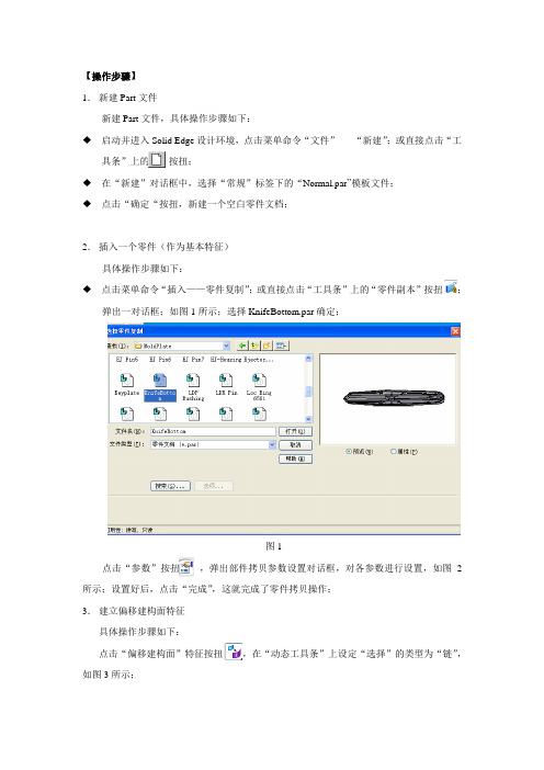
【操作步骤】1.新建Part文件新建Part文件,具体操作步骤如下:◆启动并进入Solid Edge设计环境,点击菜单命令“文件”-----“新建”;或直接点击“工具条”上的按扭;◆在“新建”对话框中,选择“常规”标签下的“Normal.par”模板文件;◆点击“确定“按扭,新建一个空白零件文档;2.插入一个零件(作为基本特征)具体操作步骤如下:◆点击菜单命令“插入——零件复制”;或直接点击“工具条”上的“零件副本”按扭;弹出一对话框;如图1所示;选择KnifeBottom.par确定;图1点击“参数”按扭,弹出部件拷贝参数设置对话框,对各参数进行设置,如图2所示;设置好后,点击“完成”,这就完成了零件拷贝操作;3.建立偏移建构面特征具体操作步骤如下:点击“偏移建构面”特征按扭,在“动态工具条”上设定“选择”的类型为“链”,如图3所示;图2图3选择部件的“面链”,如图4所示;并点击“接受”按扭;图4接着来设置偏移面的偏移方向和距离,距离为:0;点击“完成”,就完成了该步操作;4.建立拉伸特征具体操作步骤如下:点击“拉伸”特征按扭,选取X-Y平面作为参考平面,进入草图环境;来绘制一矩形;接着给草图添加约束,并标注尺寸,如图5所示,尺寸分别为:177.8、82.55、60.32;点击“完成”,返回零件设计环境。
图5接着来设置拉伸体的方向和距离,拉伸距离为34.92,延伸方向为向下,如图6所示,单击“完成”,这就完成了该步操作;图65.建立布尔运算特征,具体操作步骤如下:点击“拉伸”特征按扭,弹出一动态工具条,在动态工具条上设定选择的类型为“主体”,布尔运算的方式为“联合”即点击;接着点击刚生成的“偏移面”,点击完成,这就完成了布尔运算的操作;隐含偏移面,生成的结果如图7所示;图76.再次建立布尔运算特征,具体操作步骤如下:显示“拷贝零件”点击“拉伸”特征按扭,弹出一动态工具条,在动态工具条上设定选择的类型为“主体”,布尔运算的方式为“除料”即点击;接着点击“拷贝零件”,点击完成,这就完成了布尔运算的操作;隐含拷贝零件,生成的结果如图8所示;图87.建立除料特征具体操作步骤如下:单击“除料”命令按扭,选择矩形的一面,作为参考平面,进入草图环境;在草图环境中,单击“包含”命令按扭,弹出一对话框,来设置包含选项,如图9所示;“确定”图9选取如图10所示的几个圆,点击“完成”返回到零件设计环境中。
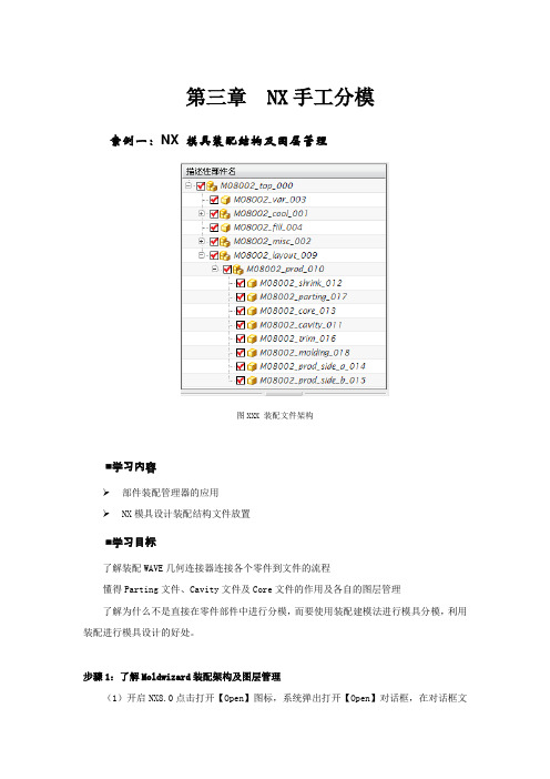
第三章 NX手工分模案例一:NX 模具装配结构及图层管理图XXX 装配文件架构■学习内容➢部件装配管理器的应用➢NX模具设计装配结构文件放置■学习目标了解装配WAVE几何连接器连接各个零件到文件的流程懂得Parting文件、Cavity文件及Core文件的作用及各自的图层管理了解为什么不是直接在零件部件中进行分模,而要使用装配建模法进行模具分模,利用装配进行模具设计的好处。
步骤1:了解Moldwizard装配架构及图层管理(1)开启NX8.0点击打开【Open】图标,系统弹出打开【Open】对话框,在对话框文件类型上选择Parasolid文本文件类型,打开选择part\chapter_02\section_02.1\ MOLD_1.x_t文件后,进入建模模块。
案例二:通过曲面修剪法分模图XXX CD机支架■学习内容➢■学习目标能步骤1:开启NX8.0打开文件part\chapter_02\section_02.3\M08003\M08003_top_000,进入建模步骤2:启动装配模块从标准【STANDARD】工具条中选择开始【START】,所有应用模块【ALL APPLICATIONS】→装配【Assemblies】,启动装配模块,系统同时弹出装配模块【Assemblies】工具条。
步骤3:添加组件在装配模块【Assemblies】那选择添加组件【Add Component】图标,弹出添加组件对话框,在打开【Open】图标那选 part\chapter_02\section_02.3\ Extract-1制品,在放置点定位那选绝对原点,如图3-001所示图3-001 添加组件步骤4 整理组件在装配导航器【Assembly Navigator】那,把新添加的制品Extract-1移动到M08003_prod_010根目录下,如图3-002所示图3-002 整理组件步骤5定义坐标把制品Extract-1设为工作部件,在编辑【Edit】下拉菜单中,选择移动对象【Move object】命令,把制品移在坐标中间(其中XC轴移动距离-50,YC轴移动距离为-50),移动后的产品如图3-003所示图3-003 移动制品步骤6 设置收缩率(1)在装配导航器【Assembly Navigator】那把M08003_shrink_012设置为工作部件,接着在装配模块【Assemblies】那选择WAVE几何链接器【WAVE Geometry linker】图标,弹出WAVE对话框,在类型那选择体【Body】,如图3-004所示,然后把Extract-1设置为空集,如图3-005所示图3-004 克隆组件图3-005 设置引用集(2)在插入【Insert】下拉菜单中,选择偏置/缩放【Offset/Scale】中的缩放体【Scale Body】命令,弹出缩放体对话框【Scale Body】,如图3-006所示图3-006 设置制品收缩率(3)在格式【Format】下拉菜单那选择移动至图层【Move to layer】命令,把设置收缩率后的制品移动到第5层,如图3-007所示图3-007 移动图层步骤7 设置工件大小(1)在图层设置【Layer Settings】那把第5层设为可见。
UGNX4模具设计实例教程本教程针对对NX4基本命令有一定了解,想学或正在学分模的人,讲述NX4分模的步骤和常用命令.这份教程讲述的是在零件环境里分模,其中只是使用MOLDWIZARD里的一些命令,这样的好处是分模完成后只有一个文件,操作方便.分模过程可以保持参数,使之有关联,也可以无参数操作. 第一章分模初步分模步骤: 打开3D图形(dcover)—结构分析—图形处理(修改结构不合理部分,加拔模斜度等等) —开始分模。
打开所附图档如下,用分析形状-面-斜率分析拨模斜度是个有效的快捷方法.(图1)图1设定参考矢量方向为Z(先用Z向分析前模,再用Z-向分析后模),把角度范围要据需要设好,选所有曲面,应用即可(图2所示),翻转移动产品,进行仔细检查,找出倒扣和无拔模斜度部分,进行修改,再用Z-方向分析后模,直至产品无问题。
至于使产品结构具备最佳模具结构性能,这就要看你的模具结构水平了。
缩水通过编辑—变换—比例来完成(完全从MOLDWIZARD进行组件分模的教材有很多,可以把我的分模方法的一部分移植上去,进行组件分模,保持参数和关联,这里不做讲述)。
从起始—所有应用模块--注塑模向导,我们开始分模。
首先,点开MOLDWIZARD的分型工具条,弹出分型管理器对话框(如图3)。
分型管理器对话框的第一项是设计区域,设计区域的第一项(面)提供了对产品所有面的拔模斜度分析和分割面的功能,斜度分析我们以在前面做过,这里的可以不用(在分模之前就应处理好出模斜度),面分割在处理一个面跨越前后模时使用(如鸡蛋)。
我们的重点用在第二项(区域),专业文档供参考,如有帮助请下载。
.UGNX4模具设计实例教程这一项为我们对产品的所有面进行前后模区域分配,自动分配不合理我们要手动更改。
点选设置区域颜色后如(图4)所示。
如果未定义的区域为0,则所有面都分配给了前后模,图2专业文档供参考,如有帮助请下载。
.UGNX4模具设计实例教程3) 图(4图退出,进行下一ok!翻转移动图形,观察各曲面的分配是否合理,不合理可以手动更改直至,抽取区域就是自动把我们前面分配给抽取区域和分型线分型管理器步。
模具设计加工教程--Cimatron China技术工程师胡志林模具设计练习教程第一部分:分模设计第一步-进入分模设计第二步-快速断开第三步-拔模角分析第四步-预览分模线第五步-创建内分模线第六步-创建内分模面第七步-创建外分模面第八步-重新附属分模面第九步-创建工件坐标系第十步-保存文档第二部分:模具设计第一步-进入模具工程第二步-进入分模环境第三步-创建分模面零件第四步-定义激活、创建激活。
第五步-加载模架第六步-创建毛坯第七步-切槽操作第八步-产品零件装配第九步-浇道设计第十步-顶杆设计第十一步-水道设计第十二步-侧滑块和斜导柱设计第十三步-行位揳紧块设计第十四步-行位限位装置设计本练习以客户实际零件lamp.elt为例讲解模具分模和模具设计的整个设计过程。
第一部分:分模设计第一步-进入分模设计选择分模设置图标, 分模设置向导即被打开。
选择文档:lamp.elt。
勾选创建新文件夹复选框。
勾选应用收缩命令改变工作模型复选框,收缩比例设置成1.008。
第二步-快速断开选择分模向导条中的快速断开图标,并更改默认的断开参数垂直面-不包括为垂直面-增加到顶部,确认。
注意到经过第一步自动断开后还有一部分曲面未被分配,选择新方向选项,并点击方向箭头端部的实心点,定义方向为沿x轴反方向,确定。
重新附属曲面,选择下图所示的应该被分配到SPLIT-3部分的曲面,然后在特征树中选择SPLIT-3特征,点击鼠标右键,再选择弹出的及时菜单中的附加选项,这样就把所选择的曲面附属到SPLIT-3部分了。
结果如下:重命名分模特征:在分模特征树上选择分模特征Split-01,点击鼠标右键,在弹出的及时菜单中选择重命名选项,更改其名称为上模,同样更改Split-02为下模,Split-03为行位。
第三步-拔模角分析选择分模向导条中拔模角度下拔模角选项,点击显示对话框选项弹出一个拔模角分析的示意图。
图中表示以颜色来区分零件模型的拔模角度。
UG手工分模教程第一步,准备工作。
首先,我们需要准备好所需的材料和工具。
材料包括分模板、胶水、纸板等。
工具包括刀具、尺子、铅笔等。
第二步,制作分模模板。
首先,根据所需物品的形状和尺寸,在纸板上绘制出分模的轮廓。
接下来,用刀具按照轮廓线剪下模板。
注意,要将模板的尺寸和形状与所需物品完全匹配。
第三步,涂胶。
将胶水均匀地涂在模板的背面,然后将其粘贴在所需物品的表面。
确保胶水涂抹均匀,以免造成分模不完整或无法拆卸的情况。
第四步,分模。
待胶水干燥后,用刀具轻轻地割开模板与物品之间的粘合部分。
这一步需要非常小心,以避免对物品造成损坏或伤害。
第五步,拆模。
当分模完成后,可以用小刀或其他工具轻轻地将模具从物品上拆下来。
如果胶水干燥时间不够长,可以稍作等待,以确保模具完全干燥。
第六步,修整。
拆下模具后,可能会有一些不完整或不平整的地方。
可以使用刀具或砂纸对这些地方进行修整,使模具更加平整和完美。
第七步,测试。
将分模模具与所需物品进行测试,确保其尺寸和形状完全匹配,并进行一些简单的操作,检查模具是否可以正常使用。
需要注意的是,UG手工分模的效果可能不如机械分模时那么精确。
如果对精度要求较高的话,建议使用机械分模。
在使用UG手工分模的过程中,还有一些技巧可以帮助我们更好地完成制作。
第一,选择合适的材料。
根据所需物品的性质和用途,选择合适的材料制作分模,以保证模具的耐用性和稳定性。
第二,控制好胶水的用量。
胶水用量不足可能导致分模不牢固,用量过多则会增加分模的难度。
因此,在涂胶的时候要控制好胶水的用量。
第三,注意刀具的使用。
刀具必须保持锋利,并在使用过程中小心操作,以免发生意外或对物品造成损害。
第四,定期清洁模具。
分模模具经常使用后,可能会受到污垢的影响,影响模具的使用效果。
因此,定期对模具进行清洁和维护非常重要。
第二章 E5风格分模设计
导言
CimatronE7的模具工程中能把分模设计和模具设计结合在一起来做,同时还保持了E5风格的单独的分模设计功能。
本章节用一个带一个侧抽的零件简要说明E5风格的分模设计过程。
第一步
1. 开始一个新的分模设计
第八步
缝合分模面,切除&删除几何
第六步
附属分模面
第七步
创建毛坯
选择分模设置图标。
分模设置向导即被打开。
选择文档:Lid.elt。
勾选创建新文件夹复选框
勾选应用收缩命令改变工作模型复选框,并接受默认收缩比例1.01。
第二步
1.快速断开
选择分模向导条中的快速断开图标,并更改默认的断开参数垂直面-不包括为垂直面-增加到顶部,确认。
注意到经过第一步自动断开后还有一部分曲面未被分配,选择新方向选项,并点击方向箭头端部的实心点,定义方向为沿Y轴,确定。
快速断开就完成了,可以使用鼠标左键拖动滑动条查看断开的效果:
2.重命名分模特征
在分模特征树上选择分模特征Split-01,点击鼠标右键,在弹出的及时菜单中选择重命名选项,更改其名称为型腔。
同样更改Split-02为型芯,Split-03为侧抽。
3.调整断开特征
从上面断开的结果看,侧抽部分还不完全,需要进行一些手工调整。
选择下图所示的平面绘制如下草图(绘制草图时可使用增加参考功能标记两个参考点)
使用曲面/断开命令,用上一步所作的矩形草图断开侧平面,如图所示:
选择下图所示的应该被分配到侧抽部分的曲面,然后在特征树中选择侧抽特征,点击鼠标右键,再选择弹出的及时菜单中的附加选项。
这样就把所选择的曲面附属到侧抽部分了。
可以再使用快速断开命令,使用滑动条查看断开效果。
第三步
1.拔模角分析
选择分模向导条中拔模角度下拔模角选项,点击显示对话框选项弹出一个拔模角分析的示意图。
图中表示以颜色来区分零件模型的拔模角度,可以看出,红色代表负角处。
拖动滑动条可以检查模型的显示颜色,看出其中有几个面显示红色,但此处明显不是倒拔模情况。
这是因为这些面的法矢方向发生了错误所致。
2.定义物体方向
选择拔模角度下的物体方向选项,选中有问题的黑色曲面,改变其法矢方向,确认。
经过这些处理,定义方向命令下没有黑色的曲面了,再返回使用拔模角分析,也没有曲面
显示红色了。
第四步
1.预览分模线
选择分模向导条中分模线下分模线预览选项,并确认。
软件则自动显示出当前的分模线。
其中内分模线以红色显示,外分模线以蓝色显示。
从中设计者可以检查分模线的情况,以保证分模的正确。
比如,分模线必须封闭,如若预览分模线中有开放的地方,则前面的快速断开肯定有不妥的地方。
2.创建内分模线
隐藏分模特征树中的分模线预览特征。
然后选择分模向导条分模线下的内分模线选项,并接受默认参数确认,则软件自动生成模型的内分模线。
3.创建内分模面
选择分模向导条分模曲面下的内分模面选项,软件则会捕捉刚创建的内分模线,自动创建内分模面。
注意到模型中心处的一条内分模线有问题,故拾取这条内分模线,取消这部分内分模面的创建。
接受创建其它的内分模面。
针对那条有问题的内分模线,设计者可以使用别的方法完成内分模面设计。
在Cimatron 分模设计中,提供了多种方式创建内外分模面,这需要设计者根据模型的特点选择相应的构建
方法。
在本例中选择分模曲面下的曲面岛屿选项,并选择内分模线处的环形平面,设置如图参数,并确认。
按下列图示创建组合曲线,并用此组合曲线创建边界曲面。
第五步
1.创建外分模线
隐藏型腔特征,创建如下组合曲线(隐藏型腔的目的就是在创建组合曲线时可以使用沿开放边选项,方便控制组合曲线的创建):
2.创建外分模面
选择分模向导条中分模曲面下的延伸曲面选项,沿刚创建的组合曲线做多方向延伸曲面,并设定延伸增量为100。
注意到上面的延伸曲面有部分变形严重,删除下列图示的两处各四个方向控制点。
删除的方法就是使用鼠标左键拾取轮廓线拐角处的叉状符号。
删除这八个方向控制点即可以确认延伸操作。
对上面创建的外分模面的缺口处的增补,选择以草图修改选项,选择刚创建的外分模面,则软件把此外分模面转换到了草图环境下。
这时对草图上的边界曲线的删除、增加等操作将直接反应到原始曲面上去。
为补充外分模面缺口,首先删除草图中缺口处的两边界轮廓,再增加连接外分模面内外轮廓的直线。
如图所示:
隐藏集合树中的curve 选项,并创建下列组合曲线:
选择扫掠面
选项,选择刚创建的组合曲线,并定义扫掠方向为沿Y 轴:
创建组合曲线:
用上面刚创建的组合曲线断开外分模面:
第六步
1.附属分模面
使用快速断开,拖动滑动条查看分模面附属情况,发现有一处分模未被附属(标示1处),有一处分模面附属错误(标示2处)。
从本例的分模状况可知,1处分模面应附属到型芯和型腔上,而2处分模面应附属到型芯和侧抽上。
这可以利用分模属性功能来完成。
选择分模属性,选择1处未附属面,中键确认,然后选择此未分配面要附属的目标:型芯和型腔曲面,确定选择。
同样方法附属2处分模面到型芯侧抽上。
注意在附属2处分模面时,由于它本身被错误的分配到了型芯和型腔上,所以在设置分模属性第二步选择附属目标时,默认选择型芯和型腔,
此时要先取消选择型腔,再选择侧抽则可。
同时需要注意的是选择附属目标时必须选择型芯、型腔和侧抽的原有模型曲面,而选择它们上的分模面则无效。
最终的结果如下图所示:
第七步
1.创建工件坐标系
选择分模向导条工具下工件坐标系选项:
切换视图,注意到分模面位置不在最低处,使用测量工具量取此差值:
选择底部特征点放置工件坐标系,并使用可选项中的增量点控制工件坐标系位于分模面位置,并确定。
2.创建毛坯
以外分模面绘制如下草图:
选择工具下新毛坯选项,创建如下毛坯:
第八步
1.输出模具部件
选择分模向导条中的输出模具部件选项,并确认保存当前文档。
则软件自动生成三个文件,如图提示:
2.缝合分模面、切除&删除几何
打开文档,在加载工件自动创建的文件夹Lid-Parting下生成了三个文件,打开其中的Lid-Work-型腔.elt。
选择分模向导条中激活工具下的分模缝合选项,则软件自动把分模面缝合成一个零件。
选择分模向导条中激活工具下的切除选项,选择毛坯作为被切除物体,选择分模面作为切除物体,并控制好切除方向,确定。
到了这时,分模面就不需要了,再使用激活工具下的删除几何选项,删除分模面即
得到了此零件的模具型腔。
注意,为了方便删除全部分模面,选择分模面时使用过滤物体过滤器。
同样方法,打开另两个文档,进行分模面缝合、切除多余毛坯和删除几何即可得到型芯和侧抽。