你清楚没有USB-C-to-USB-C-E-marker-5A数据线
- 格式:docx
- 大小:666.72 KB
- 文档页数:3

Title: USB Type-C ECR Vconn RequirementsApplied to: USB Type-C Specification Release 1.2, March 25, 2016Actual Change(a). Section 4.4.3 V CONNFrom Text:V CONN is provided by the DFP to power cables with electronics in the plug. V CONN is provided over the CC pin that is determined not to be connected to the CC wire of the cable.Initially, V CONN shall be sourced on all DFP USB Type-C receptacles that utilize the SSTX and SSRX pins during specific connection states as described in Section 4.5.2.2. Subsequently, V CONN may be removed under some circumstances as described in Table 4-3. V CONN may also be sourced by USB Type-C receptacles that do not utilize the SSTX and SSRX pins as described in Section 4.5.2.2. USB PDV CONN_Swap command also provides the DFP a means to request that the attached UFP source V CONNTable 4-4 provides the voltage and power requirements that shall be met for V CONN. See Section 4.9 for more details about Electronically Marked Cables. See Section 4.10 for a wider V CONN voltage operating range for V CONN-powered accessories. See Section 5.1 regarding optional support for an increased V CONN power range in Alternate Modes.Table 4-4 V CONN Source CharacteristicsTo aid in reducing the power associated with supplying Vconn, a Source is allowed to either not sourc Vconn or turn off Vconn under any of the following conditions:∙Ra is not detected on the CC pin after tCCDebounce when the other CC pin is in the SRC.Rd state∙Ra is not detected on the CC pin after the tCCDebounce when the other CC pin is in the SRC.Open state and supports Vconn-powered accessories.∙If there is no GoodCRC response to USB PD Discover Identity messagesTable 4-5 provides the requirements that shall be met for cables that consume V CONN power.Table 4-5 V CONN Sink CharacteristicsThe cable may remove or weaken Ra when V CONN is above 1.0 V as long as the other requirements are met. See Section 4.5.1.2.1.To Text:V CONN is provided by the DFP to power cables with electronics in the plug. V CONN is provided over the CC pin that is determined not to be connected to the CC wire of the cable.Initially, V CONN shall be sourced on all DFP USB Type-C receptacles that utilize the SSTX and SSRX pins during specific connection states as described in Section 4.5.2.2. Subsequently, V CONN may be removed under some circumstances as described in Table 4-3. V CONN may also be sourced by USB Type-C receptacles that do not utilize the SSTX and SSRX pins as described in Section B PDV CONN_Swap command also provides the DFP a means to request that the attached UFP source V CONN ArrayTable 4-4 provides the voltage and power requirements that shall be met for V CONN. See Section 4.9 for more details about Electronically Marked Cables. See Section 5.1 regarding optional support for an increased V CONN power range in Alternate Modes.Table 4-4 V CONN Source CharacteristicsTo aid in reducing the power associated with supplying V CONN, a Source is allowed to either not source V CONN or turn off V CONN under any of the following conditions:∙Ra is not detected on the CC pin after tCCDebounce when the other CC pin is in the SRC.Rd state∙Ra is not detected on the CC pin after the tCCDebounce when the other CC pin is in the SRC.Open state and supports Vconn-powered accessories∙If there is no GoodCRC response to USB PD Discover Identity messagesTable 4-5 provides the requirements that shall be met for cables that consume V CONN power.Table 4-5 Cable V CONN Sink CharacteristicsThe cable shall remove or weaken Ra when V CONN is in the valid voltage range. The cable shall reapply Ra when V CONN falls below vRaReconnect as defined in Table 4-5. The cable shall discharge V CONN to below vV CONN Discharge on a cable disconnect. The cable shall take into account the V CONNcapacitance present in the cable when discharging V CONN.Implementation Note: Increasing Ra to 20KOhm will meet both the power dissipation for Electronically Marked Passive Cables and discharge 10uF to less than vV CONN Discharge intV CONN Discharge.The maximum power consumption while in an Alternate Mode is defined by the Alternate Mode.Table 4-6 V CONN Powered Accessory Sink CharacteristicsThe V CONN powered accessory shall remove or weaken Ra when V CONN is in the valid voltage range. The V CONN powered accessory shall reapply Ra when V CONN falls below vRaReconnect as defined in Table 4-6. The V CONN powered accessory shall take into account the V CONN capacitance present in the accessory when discharging V CONN.The maximum power consumption while in an Alternate Mode is defined by the Alternate Mode.(b). Add new Cable State Machine Requirements SectionNew Text and Figures:4.5.2.4 Cable State Machine RequirementsFigure 4-18 illustrates the passive cable Electronic Marker connection state diagram. Figure 4-19 illustrates the active cable Electronic Marker connection state diagram.Figure 4-18 Passive Cable Electronic Marker State DiagramFigure 4-19 Active Cable Electronic Marker State Diagram4.5.2.4.1 Cable Power On StateThis state appears in Figure 4-18 and Figure 19. This is the initial power on state for the Electronic Marker in the cable when V CONN is applied.4.5.2.4.1.2 Cable Power On State RequirementsThe Electronic Marker in the cable shall present Ra when no V CONN is applied.The Electronic Marker in the cable shall power on may continue to present Ra in this state.The cable shall not respond to SOP’ and SOP” commands in this state.4.5.2.4.1.3 Exiting from Cable Power On StateThe Electronic Marker in a passive cable shall transition to Assign SOP’ when it has completed its boot process. The Electronic Marker in the passive cable shall transition to Assign SOP’ withintV CONN Stable, Table 5-4.The Electronic Marker in an active cable shall transition to Unassigned SOP when it has completed its boot process. The Electronic Marker in the active cable shall transition to Unassigned SOP within tV CONN Stable, Table 5-4.4.5.2.4.2 Unassigned SOP StateThis state appears in Figure 4-19. The Electronic Marker in the active cable can detect the voltage on V CONN in this state and is waiting to assign SOP’ and SOP” if supported.4.5.2.4.2.1 Unassigned SOP State RequirementsThe Electronic Marker in the active cable shall not respond to any USB PD communication sent to SOP’ or SOP” while in this state.The cable shall weaken or remove Ra if it has not already done so.The Active cable shall meet the Power for Active Cables defined in Table 4-5.The Electronic Marker in the active cable shall detect V CONN on the local cable plug or on the remote cable plug.4.5.2.4.2.3 Exiting from Unassigned SOP StateThe Electronic Marker in the active cable shall transition to Assign SOP’ when it detects V CONN present on its local cable plug and no V CONN being received from the remote cable plug.The Electronic Marker in the active cable shall transition to Assign SOP” when it detects V CONN being received from the remote cable plug and it does not detect V CONN from its local cable plug. The Electronic Marker in the active cable may stay in Unassigned SOP if it does not supports SOP”.The Electronic Marker in the active cable should remain in Unassigned SOP if it detects V CONN present on the local cable plug and the remote cable plug at the same time.4.5.2.4.3 Assign SOP’ StateThis state appears in Figure 4-18 and Figure 4-19. The cable Electronic Marker responds to SOP’ in this state.4.5.2.4.3.1 Assign SOP’ State RequirementsThe Electronic Marker in the passive or active cable shall be able to respond to any USB PD communication sent to SOP’.The Electronic Marker in the passive cable shall weaken or remove Ra if it has not already done so.Passive cables shall meet the Power for Electronically Marked Passive Cables defined in Table 4-5.Active Cables shall meet the Power for Active cables in Table 4-5.4.5.2.4.3.2 Exiting from Assign SOP’ StateThe Electronic Marker in the passive or active cable shall transition to Cable Power On upon sensing V CONN less than vRaReconnect defined in Table 4-5 or upon a Power On Reset event.The Electronic Marker in the passive cable shall transition to Cable Power On upon sensing a Hard Reset or Cable Reset.The Electronic Marker in the active cable shall transition to Unassigned SOP upon sensing a Hard Reset or Cable Reset.4.5.2.4.4 Assign SOP” State (Optional Normative)This state appears in Figure 4-19. The active cable Electronic Marker responds to SOP” in this state. This state is not required to be supported by an active cable.4.5.2.4.4.1 Assign SOP” State RequirementsThe Electronic Marker in the active cable shall be able to respond to any U SB PD communication sent to SOP”.The Electronic Marker shall weaken or remove Ra to meet the maximum power defined in Table 4-5 if it has not already done so.4.5.2.4.4.2 Exiting from Assign SOP” StateThe Electronic Marker in the active cable shall transition to Cable Power On upon sensing Vconn less than vRaReconnect defined in Table 4-5 or on a Power On Reset event.The Electronic Marker in the active cable shall transition to Unassigned SOP upon sensing a Hard Reset or Cable Reset.(c). Section 4.6.1.2 V CONN Requirements during USB Suspend, Page168From Text:4.6.1.2 VCONN Requirements during USB SuspendIf the Source supplies V BUS power during USB suspend, it shall also supply at least 7.5 mA to V CONN. Electronically marked cables shall draw no more than 7.5 mA from V CONN during USB suspend.To Text:4.6.1.2 VCONN Requirements during USB SuspendIf the Source supplies V BUS power during USB suspend, it shall also supply V CONN and meet the requirements defined in Table 4-4.Electronically marked cables shall meet the requirements in Table 4-5 during USB suspend.V CONN powered accessories shall meet the requirements defined in Table 4-6 during USB suspend.(d). Section 4.10 V CONN– Powered Accessories, Page 176From Text:A V CONN-powered accessory is a direct-attach Sink that implements an Alternate Mode (See Section5.1) and can operate with just V CONN.The V CONN-powered accessory exposes a maximum impedance to ground of Ra on the V CONN pin and Rd on the CC pin.When operating in the UFP role and when V BUS is not present, V CONN-powered accessories shall treat the application of V CONN as an attach signal, and shall respond to USB Power Delivery messages.When powered by only V CONN, a V CONN-powered accessory shall negotiate an Alternate Mode. If it fails to negotiate an Alternate Mode within tAMETimeout, its port partner removes V CONN.V CONN-powered accessories shall be able to operate over a range of 2.7 V to 5.5 V on V CONN.The removal of V CONN when V BUS is not present shall be treated as a detach event.When V BUS is supplied, a V CONN-powered accessory is subject to all of the requirements for Alternate Modes, including presenting a USB Billboard Device Class interface if negotiation for an Alternate Mode fails.To Text:A V CONN-powered accessory is a direct-attach Sink that implements an Alternate Mode (See Section5.1) and can operate with just V CONN.The V CONN-powered accessory exposes a maximum impedance to ground of Ra on the V CONN pin and Rd on the CC pin.When operating in the Sink role and when V BUS is not present, V CONN-powered accessories shall treat the application of V CONN as an attach signal, and shall respond to USB Power Delivery messages. When powered by only V CONN, a V CONN-powered accessory shall negotiate an Alternate Mode. If it fails to negotiate an Alternate Mode within tAMETimeout, its port partner removes V CONN.V CONN-powered accessories shall comply with Table 4-6.The removal of V CONN when V BUS is not present shall be treated as a detach event.When V BUS is supplied, a V CONN-powered accessory is subject to all of the requirements for Alternate Modes, including presenting a USB Billboard Device Class interface if negotiation for an Alternate Mode fails.(e). Section 4.9 Electronically Marked Cables, Pages 175 - 176From Text:4.9 Electronically Marked CablesAll USB Full-Featured Type-C cables shall be electronically marked. USB 2.0 Type-C cables may be electronically marked.Electronically marked cables shall support USB Power Delivery Structured VDM Discover Identity command d irected to SOP’. This provides a method to determine the characteristics of the cable, e.g. its current carrying capability, its performance, vendor identification, etc. This may be referred to as the USB Type-C Cable ID function.Prior to an explicit USB PD contract, a Sourcing Device is allowed to use SOP’ to discover the cable’s identity. After an explicit USB PD contract has been negotiated, only the Source shall communicate with SOP’ and SOP” (see Section 5.2.2).An electronically marked cable incorporates electronics that require V CONN, although V BUS or another source may be used. Electronically marked cables that do not incorporate data bus signal conditioning circuits shall consume no more than 70 mW from V CONN. During USB suspend, electronically marked cables shall not draw more than 7.5 mA from V CONN, see Section 4.6.1.2.Figure 4-37 illustrates a typical electronically marked cable. The isolation elements (Iso) shall prevent V CONN from traversing end-to-end through the cable. Ra is required in the cable to allow the Source to determine that V CONN is needed.Figure 4-38 illustrates an electronically marked cable where the V CONN wire does not extend through the cable, therefore an SOP’ element is required at each end of the cable. In this case, no isolation elements are needed.For cables that only respond to SOP’, the location of the responder is not relevant.An active cable is an electronically marked cable that incorporates data bus signal conditioning circuits, for example to allow for implementing longer cables. Active cables shall not draw more than 1 W from V CONN, see Section 4.4.3.Active cables may or may not require configuration management. Requirements for active cables that require configuration management are provided in Section 5.2.Refer to Section 4.4.3 for the requirements of a Source to supply V CONN. When V CONN is not present, a powered cable shall not interfere with normal CC operation including Sink detection, current advertisement and USB PD operation.To Text:4.9 Electronically Marked CablesAll USB Full-Featured Type-C cables shall be electronically marked. USB 2.0 Type-C cables may be electronically marked.Electronically marked cables shall support USB Power Delivery Structured VDM Discover Identity command directed to SOP’. This provides a method to determine the characteristics of the cable, e.g. its current carrying capability, its performance, vendor identification, etc. This may be referred to as the USB Type-C Cable ID function.Prior to an explicit USB PD contract, a Sourcing Device is allowed to use SOP’ to discover the cable’s identity. After an explicit USB PD contract has been negotiated, only the Source shall communicate with SOP’ and SOP” (see Section 5.2.2).Electronically marked passive cables shall follow the Cable State Machine defined in 4.5.2.4 and Figure 4-18.An E lectronically marked cable s incorporates electronics that require are generally powered fromV CONN, although V BUS or another source may be used.Electronically marked cables that do not incorporate data bus signal conditioning circuits shall consume no more than 70 mW from V CONN.shall meetthe maximum power defined in Table 4-5. During USB suspend, electronically marked cables shall not draw more than 7.5 mA from V CONN, see Section 4.6.1.2.Refer to Table 4-4 for the requirements of a Source to supply V CONN. When V CONN is not present, a powered cable shall not interfere with normal CC operation including Sink detection, current advertisement and USB PD operation.Figure 4-37 illustrates a typical electronically marked cable. The isolation elements (Iso) shall prevent V CONN from traversing end-to-end through the cable. Ra is required in the cable to allow the Source to determine that V CONN is needed.Figure 4-38 illustrates an electronically marked cable where the V CONN wire does not extend through the cable, therefore an SOP’ element is required at each end of the cable. In this case, no isolation elements are needed.For cables that only respond to SOP’, the location of the responder is not relevant.4.9.1 Parameter ValuesTable 4-15 provides the power on timing requirements for SOP’ and SOP” to be ready to communicate.Table 4-15 SOP’ and SOP” Timing4.9.2 Active CablesAn active cable is an electronically marked cable that incorporates data bus signal conditioning circuits, for example to allow for implementing longer cables. Active cables with data bus signal conditioning in both plugs shall implement SOP’ and may implement SOP”. Active cables shall not draw more than 1 W from V CONN, see Section 4.4.3. meet the power requirements defined in Table 4-5.Active cables may support either one SSTX/SSRX pair or two SSTX/SSRX pairs. The Electronic Marker in the cable shall identify the number of SSTX/SSRX lanes supported.Active cables may or may not require configuration management for alternate modes. Requirements for a Active cable s that require configuration management is defined are provided in Section 5.2.(f). Section 5.2 Managed Active Cables, Pages 190 - 192From Text:5.2 Managed Active CablesActive cables that require configuration (managed active cable) shall use USB Power Delivery StructuredVDMs to discover and configure the cable.USB Power Delivery Structured VDMs provide a standardized mechanism for identifying and managing thefunctionality of active cables.Some managed active cables only have a single USB PD controller in the cable that responds to USB PDStructured VDMs sent to SOP’.When a managed active cable requires independent management at each end of the cable, separate USB PD controllers responding to USB PD Structured VDMs sent to SOP’ and SOP” can be located in each plug.5.2.1 Requirements for Managed Active Cables that respond to SOP’ and SOP”After a power-on reset event or a USB PD Hard Reset, the USB PD controller attached to the Source is assignedSOP’ and the USB PD controller attached to the Sink is assigned SOP”. After a USB PD Cable Reset, the plug being supplied V CONN responds to SOP’ independent of whether it is the plug atta ched to the Source or Sink.The controllers can sense whether they are SOP’ or SOP” based on the presence of V CONN at the plug’s V CONNpin as only one port supplies V CONN.Figure 5-6 illustrates the process that shall be followed to assign SOP’ and SOP” to the ends attached to theSource and Sink, respectively, at power on. In the Unassigned state, the active cable will not respond to any USB PD communication sent to SOP’ or SOP”. The parameter tV CONN Stable allows time for the active cable to set up to communicate.When V CONN is removed, the plug’s local V CONN shall discharge to below its SOP’ detection threshold within 20 ms.A managed active cable shall assure that the two USB PD controllers are uniquely assigned via the mechanism described here, one as SOP’ and the other as SOP”.USB PD supports three types of USB Type-C-related swaps that may or may not impact V CONN:• USB PD V CONN_Swap – The port previously not supplying V CONN sources V CONN and the assignment of SOP’ and SOP” remain unchanged.• USB PD DR_Swap –The assignment of SOP’ and SOP” remain unchanged.• USB PD PR_Swap –The assignment of SOP’ and SOP” remain unchanged.Managed active USB Type-C to USB Type-C cables shall by default support USB operation. Multi-modal cables (e.g., an active cable that supports an Alternate Mode in addition to USB SuperSpeed) that use the TX/RX signal pairs shall minimally support USB 3.1Gen 1 operation. They are encouraged to support both Gen 1 and Gen 2 operation.Figure 5-7 illustrates a typical managed active cable. The isolation elements (Iso) shall prevent V CONN from traversing end-to-end through the cable. Ra is required in the cable to allow the DFP to determine that V CONN is needed.5.2.1.1 Parameter ValuesTable 5-2 provides the power on timing requirements for SOP’ and SOP” to be ready to communicate.Table 5-4 SOP’ and SOP” Timing5.2.2 Cable Message StructureUSB PD Structured VDMs shall be used to identify and manage active cables. Cables that require additionalfunctionality, for example to program parameters in the active electronics, may define proprietary Structured VDMs to provide the necessary functionality. In all cases, these messages shall only use SOP’ and SOP”. Theyshall not use SOP.SOP’ and SOP” are defined to allow a vendor to communicate individually with each end the cable.For active cables that support both SOP’ and SOP”, after attach or a USB PD Cable Reset, the plug directlyconnected to the Source shall only respond to SOP’ and the plug directly connected to the Sink shall only respond to SOP”.The assignment of SOP’ and SOP” to each plug remains persistent until V CONN is removed or a subsequent USB PD Cable Reset.The Discover Identity message shall start with SOP’.To Text:5.2 Managed Active CablesManaged active cables may have a single USB PD controller in the cable that responds to USB PD Structured VDMs sent to SOP’ if independent management of each end is not required.All managed active cables shall identify if they respond to SOP’ only or to both SOP’ and SOP” using the Discover Identity command defined in USB Power Delivery.5.2.1 Requirements for Managed Active Cables that respond to SOP’ and SOP”Managed active cables shall implement the Cable State Machine defined in 4.5.2.4 and Figure 4-19.A managed active cable which supports two USB PD controllers shall ensure the cable plugs are uniquely assigned via the mechanism described here, one as SOP’ and the other as SOP”.USB PD supports three types of USB Type-C-related swaps that may or may not impact V CONN:• USB PD V CONN_Swap – The port previously not supplying V CONN sources V CONN and the assignment of SOP’ and SOP” remain unchanged.• USB PD DR_Swap –The assignment of SOP’ and SOP” remain unchanged.• USB PD PR_Swap –The assignment of SOP’ and SOP” remain unchanged.Managed active USB Type-C to USB Type-C cables shall by default support USB operation. Modal cables (e.g., an active cable that supports an Alternate Mode in addition to USB SuperSpeed) that use the TX/RX signal pairs shall minimally support USB 3.1Gen 1 operation and are encouraged to support both Gen 1 and Gen 2 operation.Figure 5-7 illustrates a typical managed active cable. The isolation elements (Iso) shall prevent V CONN from traversing end-to-end through the cable. Ra must be present when no V CONN is applied to allow the DFP to determine that V CONN is needed.5.2.2 Cable Message StructureUSB PD Structured VDMs shall be used to identify and manage active cables. Cables that require additional functionality, for example to program parameters in the active electronics, may define proprietary Structured VDMs to provide the necessary functionality. In all cases, these messages shall only use SOP’ and SOP”. They shall not use SOP.SOP’ and SOP” are defined to allow a vendor to communicate individually with each cable end.The Discover Identity message shall start with SOP’.Source Sink。


pd协议最新版本USB PD(Power Deliver)协议是USB IF协会制定的USB充电标准与技术,是目前主流的快充协议之一,其最大供电能力可达100W,被应用在各种设备的电源上。
USB PD协议利用USB Type-C接口的CC(Configuration channel)引脚作为数据传输通道来协商充电的电压、电流和功率传输方向,在介绍USB PD协议的具体内容之前,先简单介绍一下其依赖的USB Type-C接口。
如上图所示,Type-C接口可以完全替代Type-A、Type-B、Micro AB等各种USB接口,实现数据传输、电力传输。
USB PD协议就是基于Type-C接口的强大功能实现的。
Type-C接口的引脚示意图如下所示,VBUS为总线电源,D+、D-为USB2.0的差分信号线,TX+、TX-、RX+、RX-为SuperSpeed差分信号,SBU (Sideband Use)为旁路使用,CC为配置通道。
Type-C接口最大功率传输可达100W(20V/5A),最大数据传输速率为10Gbps。
可以看到,在公头上只有一个CC 引脚,母头上的CC引脚是对称的,所以也可以利用CC引脚判断正反插。
USB PD协议的工作原理是利用Type-C接口的CC线作为数据线来协商电压、电流以及供电方向,整个通信过程需要按照特定的数据包格式,并且存在相互认证的过程。
下面先介绍一些USB PD中常见的名词,这些名词在后面也会用到。
Source:通常指电源提供端,如电源适配器。
Sink:通常指电源消耗端,如手机、平板。
E-Marker(electronic marker):电子标记,一般存在于Type-c to Type-c的线缆中。
CC(Configuration Channel) :配置通道,用于识别、控制等。
BMC(Biphase Mark Coding):双相位标识编码,通过CC通信。
DFP(Downstream Facing Port):下行端口,即为HOST或者HU B下行端口。

USB Type-C凭借其自身强大的功能,在Apple, Intel, Google等厂商的强势推动下,必将迅速引发一场USB接口的革命,并将积极影响我们日常生活的方方面面。
本文讨论一个重要的专业问题:USB Type-C设备到底是否需要CC逻辑检测与控制芯片?要回答这个问题,我们得先从基本概念谈起。
DFP(Downstream Facing Port): 下行端口,可以理解为Host,DFP提供VBUS,也可以提供数据。
典型的DFP设备是电源适配器,因为它永远都只是提供电源。
UFP(Upstream Facing Port): 上行端口,可以理解为Device,UFP从VBUS中取电,并可提供数据。
典型设备是U盘,移动硬盘,因为它们永远都是被读取数据和从VBUS取电,当然不排除未来可能出现可以作为主机的U盘。
DRP(Dual Role Port): 双角色端口,DRP既可以做DFP(Host),也可以做UFP(Device),也可以在DFP与UFP间动态切换。
典型的DRP设备是电脑(电脑可以作为USB的主机,也可以作为被充电的设备(苹果新推出的MAC Book Air)),具OTG功能的手机(手机可以作为被充电和被读数据的设备,也可以作为主机为其他设备提供电源或者读取U盘数据),移动电源(放电和充电可通过一个USB Type-C,即此口可以放电也可以充电)。
CC(Configuration Channel):配置通道,这是USB Type-C里新增的关键通道,它的作用有检测USB连接,检测正反插,USB设备间数据与VBUS的连接建立与管理等。
USB PD(USB Power Delivery): PD是一种通信协议,它是一种新的电源和通讯连接方式,它允许USB设备间传输最高至100W(20V/5A)的功率,同时它可以改变端口的属性,也可以使端口在DFP与UFP之间切换,它还可以与电缆通信,获取电缆的属性。


企业标准Micro-USB接口定义文件版本:1.0拟制:审核:会签:批准:文件编号:JSBZ-PG-0003 生效日期:2009-12-16版本号:V1.0耳机端:2、基本参数受话器电性能参数:麦克风电性能参数:3、线材性能:直流电阻值:〈1欧姆/1M,绝缘阻抗:〉10M欧姆,受话器的GND要与MIC的GND分开。
最后在公头连接处相连。
如图所示:三、USB下载线与数据线图及说明1、下载线与数据线连线图图三USB转串口线连线图2、下载线与数据线说明1、下载线说明该数据线为工厂定制+生产部加工。
该数据线分别连接计算机的标准USB 接口和手机的系统连接器,将计算机的USB 接口转换成串口的接口和电平转换,完成手机与计算机的通讯。
该线完成的功能有:将手机代码通过工具软件下载到手机主板;通过工具软件实现计算机备份及管理手机电话簿,通过计算机发送短信息等功能;通过修改计算机设置,可使计算机通过手机上互联网。
注意事项:1)特别要求GND 与外壳的地连接起来,并保证焊接质量接地良好。
2)外接电源的电压要求是3.5~4.2V。
3)外接电源时请注意电源的正、负极。
红色线接电源正极(+),黑色线接电源负极(-)。
2、数据线说明1)数据线的一端为USB接口,另一端为MINI USB接口。
2)数据线的各个接线端子需要保护。
3)最大工作电流小于400mA。
4)数据线连续工作至少要保证16小时。
5)数据线的长度为1500+/-30mm。
6)特别要求GND 与外壳的地连接起来,并保证焊接质量接地良好。
7)数据线金属接头的外漏长度根据实际的壳体外形,可以和厂商沟通调整。
四、手机主板母座标准尺寸图。


一、概述因为每个USB接口能够向外设提供+5V500MA的电流,当我们在连接板载USB接口时,一定要严格按照主板的使用说明书进行安装。
绝对不能出错,否则将烧毁主板或者外设。
相信有不少朋友在连接前置USB插线时也发生过类似的“冒烟事见“。
这就需要我们能够准确判别前置USB线的排列顺序如果我们晓得USB接口的基本布线结构,那问题不是就迎刃而解了吗。
二、USB接口实物图主机端:接线图:VCCData-Data+GND实物图:设备端:接线图:VCCGNDData-Data+三、市面上常见的USB接口的布线结构这两年市面上销售的主板,板载的前置USB接口,使用的都是标准的九针USB接口,第九针是空的,比较容易判断。
但是多数品牌电脑使用的都是厂家定制的主板,我们维修的时候根本没有使用说明书;还有像以前的815主板,440BX,440VX主板等,前置USB的接法非常混乱,没有一个统一的标准。
当我们维修此类机器时,如何判断其接法呢?现在,把市面上的比较常见的主板前置USB接法进行汇总,供大家参考。
(说明:■代表有插针,□代表有针位但无插针。
)1、六针双排这种接口不常用,这种类型的USB插针排列方式见于精英P6STP-FL(REV:1.1)主板,用于海尔小超人766主机。
其电源正和电源负为两个前置USB接口共用,因此前置的两个USB接口需要6根线与主板连接,布线如下表所示。
■DATA1+■DATA1-■VCC■DATA2-■DATA2+■GND2、八针双排这种接口最常见,实际上占用了十针的位置,只不过有两个针的位置是空着的,如精英的P4VXMS(REV:1.0)主板等。
该主板还提供了标准的九针接法,这种作是为了方便DIY在组装电脑时连接容易。
■VCC■DATA-■DATA+□NUL■GND■GND□NUL■DATA+■DATA-■VCC微星MS-5156主板采用的前置USB接口是八针互反接法。
虽然该主板使用的是Intel 430TX 芯片组,但首先提供了当时并不多见的USB1.0标准接口两个,只不过需要使用单独的引线外接。

国标充电接口标准是指中国国家标准规定的充电接口规范。
这些标准旨在确保充电器和设备之间的兼容性,提高充电效率,降低能耗,保障用户的安全使用。
目前,中国的国标充电接口标准主要包括以下几种:
1. USB-A 接口:这是最常见的充电接口,广泛应用于各种电子设备,如手机、平板电脑、电脑等。
USB-A 接口支持最大5V/
2.4A的输出功率。
2. USB-C 接口:这是一种较新的充电接口,具有更高的传输速度和充电效率。
USB-C 接口支持最大100W的输出功率,可以用于为笔记本电脑、平板电脑、手机等设备充电。
3. Micro-USB 接口:这是一种较为常见的充电接口,主要用于手机、平板电脑等小型电子设备。
Micro-USB 接口支持最大5V/2.0A的输出功率。
4. Lightning 接口:这是苹果公司为其产品(如iPhone、iPad等)设计的专用充电接口。
Lightning 接口支持最大12W的输出功率。
5. QC(Quick Charge)快充协议:这是一种由高通公司推出的快速充电技术,可以显著提高充电速度。
QC 快充协议兼容多种充电接口,如USB-A、USB-C等。
6. PD(Power Delivery)快充协议:这是一种由USB-IF组织推出的新一代快速充电技术,具有更高的充电效率和兼容性。
PD 快充协议兼容USB-C接口,支持最大100W的输出功率。
在选择充电器时,请确保其符合您设备的充电接口标准,以保证充电效果和安全使用。
同时,为了保护电池寿命,建议尽量使用原装或认证的充电器进行充电。


关头词:TYPE C、数据线之五兆芳芳创作摘要:本文介绍了数据线的规格,性能及测试标准.缩略语:1规模尺度适用于TYPE A TO C数据线需求规格书,未尽规格描述以TYPE C协会标准V1.1为准.2编写依据3数据线正常任务和存储条件3.1数据线应能在下列条件下正常任务:3.1.1 任务情况温度:20℃~+55℃;(仅作单体验证目的,与整机匹配时以整机试验情况为准);3.1.2 相对湿度:5%~95%;3.1.3 大气压力:86 kPa~106kPa;3.1.4 数据线的存储温度:40℃~+85℃;4数据线主要参数4.1数据线连线规格详细尺寸以及工艺要求以3D图档为准1、type C金属插头,要求必须是整体拉伸成型,不克不及是折弯成型,不接受接缝;2、金属插头部分,要求做不锈钢原色,概略喷砂处理:50u”~150u” MATT NICKEL PLATING OVER ALL3、包管至少3A通流能力整条线缆产品详细规格(BOM清单, 包含端子图纸2D & 可拆解版本的3D)要有确认才干认可(认证时必须提供以上文件).4.2线材主体信息:4.2.1外不雅5V/3A A plug TO C plug, cover式,白色半雾面,素材细咬花处理,MT110064.2.2主体结构导体材质规格如下:材质:镀锡铜绝缘材质NONPVC,须满足5.2章节测试性能要求4.2.3关头尺寸4.2.3.1USB2.0 B plug参考协会标准4.2.3.2TYPEC plug1.红圈标示尺寸为重点尺寸,其余尺寸依据协会标准要求2.各组件BOM LIST原资料信息需明确到具体牌号4.2.3.3镀层厚度测试区域规则关于镀层测试区域和办法:TYPE C/A:TYPE C/A产生接触的关头区域为PIN针头部触点,因此镀层工艺为考虑成本一般只笼盖PIN针触点位置,其他区域为flash Au,所以镀层的量测规模定义在PIN针触点弧顶的最高处4.2.4线序Table 320 USB TypeC to USB 2.0 AMWiring USB TypeC PlugUSB 2.0 AMPin Signal Name Pin Signal Name 镀层厚度为在触点弧顶最高点的规模内进行丈量,同一触点在规模内丈量三次取平均值5技巧要求5.1线材外不雅要求5.1.1线材外不雅要求如下:未尽事宜参考《终端数据线查验通用操纵指导书》5.2线材性能要求Test conditionTemperature:15℃ to 35℃Air pressure :86 to106 kPaRelative humidity:25% to 85%5.3平安性要求USB数据线的平安性能应能满足CCEE规则要求.合适国际GB 49431995 《信息技巧设备(包含电器事务设备)的平安》规则的要求.5.3.1阻燃要求:塑胶件/PCB:UL94V0满足IEC60332或GB/T18380电缆在火焰条件下的燃烧试验尺度(欧洲、国际).参考尺度:IEC60950/EN60950/UL60950/GB4943、IEC60332/GB/T18380、UL15815.4环保要求本技巧要求数据线所有组成资料合适《Huawei Substance List V 4.0》禁用物质要求、无卤及无邻苯二甲酸酯、三氧化二锑、铍及其化合物要求、ROHS、WEEE、Reach要求.6包装标记产品的运输包装收发货标记应合适GB/T 6388-1996的规则,并经我公司认可.产品本体需要OPP膜防刮花,出厂前贴二维码标识6.1外包装箱6.2产品标签标签需采取二维码形式包含如下信息:认证标识、厂家信息、生产批次等6.2.1产品及格证产品及格证的编写应合适GB/T 14436的规则.a)应有及格证,规格为27*27mm菱形及格证标签;b)及格证上应有查验者标识、查验日期、产品型号等.7包装、运输、贮存7.1使用盘装7.2运输包装后的产品应能以任何交通东西,运往任何地点.在长途运输时,不得装在敞蓬的船和车厢,中途转运时不得存放在露天仓库中,在运输进程中不允许与易燃、易爆、易腐化的物品同车装运,产品不允许经受雨、雪或液体物质的淋袭和机械损伤.7.3贮存产品贮存应保持原有包装,存放产品仓库应有防潮、防尘、防震、防腐化等设施.贮存条件为:温度:40℃~+85℃相对湿度:10%~95%大气压:86 kPa~106kPa贮存方法:包装存放.8附录:组合测试要求:。

USB Type-C凭借其自身强大的功能,在Apple, Intel,Google等厂商的强势推动下,必将迅速引发一场USB接口的革命,并将积极影响我们日常生活的方方面面。
为了能够使自己的设备兼容这些接口,通常需要增加一个TYPEC接口CC逻辑控制芯片,但其实并不是每一种设备都需要增加CC逻辑控制芯片(例如: Legendary Technology LDR6013)。
本文讨论一个重要的专业问题:USB Type-C设备到底是否需要CC逻辑检测与控制芯片?要回答这个问题,我们得先从基本概念谈起。
DFP(Downstream Facing Port):下行端口,可以理解为Host,DFP提供VBUS,也可以提供数据。
典型的DFP设备是电源适配器,因为它永远都只是提供电源。
UFP(Upstream Facing Port):上行端口,可以理解为Device,UFP从VBUS中取电,并可提供数据。
典型设备是U盘,移动硬盘,因为它们永远都是被读取数据和从VBUS取电,当然不排除未来可能出现可以作为主机的U盘。
DRP(Dual Role Port):双角色端口,DRP既可以做DFP(Host),也可以做UFP(Device),也可以在DFP与UFP间动态切换。
典型的DRP设备是电脑(电脑可以作为USB的主机,也可以作为被充电的设备(苹果新推出的MacBook),具OTG功能的手机(手机可以作为被充电和被读数据的设备,也可以作为主机为其他设备提供电源或者读取U盘数据),移动电源(放电和充电可通过一个USB Type-C,即此口可以放电也可以充电)。
CC(Configuration Channel):配置通道,这是USB Type-C里新增的关键通道,它的作用有检测USB连接,检测正反插,USB设备间数据与VBUS的连接建立与管理等。
USB PD(USB Power Delivery):PD是一种通信协议,它是一种新的电源和通讯连接方式,它允许USB设备间传输最高至100W(20V/5A)的功率,同时它可以改变端口的属性,也可以使端口在DFP与UFP之间切换,它还可以与电缆通信,获取电缆的属性。

type-e to idc接线标准是一种常见的连接方式,用于将电线或电缆连接到电路板或其他电子设备上。
以下是Type-E to IDC接线标准的常见规范和要求:
1.连接器类型:Type-E to IDC接线标准使用的是一种插入式连接
器,也称为IDC连接器。
这种连接器有一个插槽,用于接收一个电线或电缆的绝缘层,并通过机械压力将芯线固定在连接器中。
2.芯线直径:根据所使用的电线或电缆类型,芯线的直径可能会
有所不同。
一般来说,芯线的直径范围在22-24 AWG(美国线规)之间。
3.绝缘层直径:绝缘层的直径通常比芯线直径略大,以确保顺利
插入连接器。
常见的绝缘层直径范围在24-26 AWG(美国线规)之间。
4.颜色编码:为了方便识别和区分不同的芯线,Type-E to IDC接
线标准通常采用颜色编码方案。
常见的颜色编码方案包括单色编码、双色编码和三色编码等。
5.标记和标识:为了方便安装和维护,Type-E to IDC接线标准要
求在连接器的外壳上标记有明确的标识,以指示每个连接器的功能和用途。
6.机械强度:Type-E to IDC接线标准要求连接器必须具有一定的
机械强度,以确保在使用过程中不会出现松动或脱落的情况。
7.环境适应性:根据使用环境的不同,Type-E to IDC接线标准可
能会有不同的环境适应性要求。
例如,某些应用可能需要连接器能够承受高温、潮湿、振动等恶劣环境条件。
总之,Type-E to IDC接线标准是一种常见的连接方式,需要遵循一定的规范和要求,以确保连接的可靠性和稳定性。

普通充电器给苹果IPHONE/IPAD2充电的USB端的识别电阻的设置充电器插头一端插在220V交流电的插座上,另一端用苹果专用的数据线接到iPhone/iPad上。
220V交流电先通过整流电路和滤波电路变成300V高压直流电,再经过开关管变成高频高压脉冲,然后通过变压器转换为低压(比如5V)脉冲。
5V的低压脉冲再经过一个整流、稳压电路,变成5V稳定的直流电。
在从220V交流电变为5V直流电的整个过程中,变压器、整流电路、稳压电路只是起到一个改变电能形态的作用。
如果稳压电路输出5V的一端(USB接口)没有接上iPad或者iPhone(术语称为负载),就不会有电流流过,也就不会消耗电能。
接上负载之后,充电器输出端子的正负极才有电流,流过充电器的电流大小取决于负载的状态:只要在力所能及的范围内,负载需要多大的电流,充电器就提供多大的电流。
如果负载需要的电流超过了充电器能够提供的电流上限,那么充电器就会一直输出这个最大的电流。
这是因为,充电器内部通常会设计保护电路,一旦输出电流过大,就会触发保护机制,暂停电流输出。
不过,苹果公司为了让旗下的所有充电器和数码产品能够尽量混用,想出了一个奇招:仔细观察一下充电器的USB接口,你会发现一共有四个窄金属条,称为四个引脚。
这四个引脚分别连接5V电源、D+数据线正信号、D-数据线负信号和GND地。
标准USB引脚,电压分别是:VCC,D-,D+,GROUD;+5V,0,0,0苹果用D-,D+线的电压来检测是否是原装充电器,以决定充电电流。
IPHONE,5V,2.7V,2V,0这样最大充电电流1A;IPAD 5V,2V,2.7V,0 充电电流。
一般兼容USB接口的充电器,D+和D-两个引脚是悬空的,任何设备只要插上这样的充电器,就会从5V和GND 两个引脚获得电能。
而苹果的充电器则在D+和D-两个数据引脚上增加了分压电阻,使充电的设备能够在充电时从这两条数据线上读到两个电压。
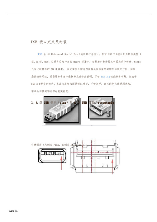
USB 接口定义及封装USB全称 Universal Serial Bus(通用串行总线),目前 USB 2.0接口分为四种类型 A 型、B 型、Mini 型还有后来补充的 Micro 型接口,每种接口都分插头和插座两个部分,Micro 还有比较特殊的 AB 兼容型,本文简要介绍这四类插头和插座的实物及结构尺寸图,如果是做设计用途,还需要参考官方最新补充或修正说明,尽管 USB 3.0性能非常卓越,但由于USB 3.0规变化较大,真正应用起来还需假以时日,不管怎样,都已经把火线逼到末路,苹果公司极其郁闷但也爱莫能助。
1、A型 USB插头(plug)和 A型 USB插座(receptacle)引脚顺序(左侧为 Plug,右侧为 Receptacle):引脚定义:编号1234 定义VBUSD-D+GND颜色识别Red(红色)White(白色)Green(绿色)Black(黑色)封装尺寸(单 PIN Receptacle):2、B型 USB插头(plug)和 B型 USB插座(receptacle)引脚顺序(左侧为 Plug,右侧为 Receptacle,注意箭头所指斜口向上,USB 端口朝向自己):引脚定义、封装尺寸均与 A 型 USB引脚说明相同。
封装尺寸(单 PIN Receptacle):3、Mini B型 USB插头(plug)和 Mini B型 USB插座(receptacle)引脚顺序(左侧为 Plug,右侧为 Receptacle,注意宽边在上,USB 端口朝向自己):引脚定义:编号12345封装尺寸(Receptacle):定义VBUSD-D+IDGND颜色识别Red(红色)White(白色)Green(绿色)Not connected(未连接)Black(黑色)以上部分为 USB 2.0规容,下面的 Micro USB 实际上是在2006年才发布的补充规,由于该接口定义无法后向支持 USB 3.0协议,故仍然归于 USB 2.0协议包。

米鹿移动电源ML-001 5000mAh,为智慧型手机和平板电脑而生!研发团队亲情奉献惊喜特别推广价:RMB ¥58元!!附图:带包装盒的产品外观●为iPhone而设计,支持 iPhone, iPhone 3G, iPhone 3GS, iPhone 4;支持 iPad,以及所有的iPod,包括iPod touch!●支持Nokia诺基亚全系列!●支持HTC全系列!●支持MOTO全系列!●支持其他任何USB充电方式的手机!●不单单是手机,还可为MP3、 MP4、PSP游戏机等各种USB设备充电。
●甚至还支持夏天的USB风扇,冬天的USB暖手袋。
产品参数产品型号:ML-001充电电压:5V标称电压:5.3V最小容量:5000mAh标准充电:0.9A标准充电方法以:USB-1:5.3V-0.8AUSB-2:5.3V-1.5A标准充电:1小时800mAh快速充电:1小时1500mAh最大充电电流:1A最大放电电流:1.5A放电截止电压:3.0V工作温度:充电:-10℃~45℃放电:-20℃~60℃储存温度:-20°C ~ + 60°C电池重量:约124g以下电源尺寸:长110*宽72*厚16mm米鹿移动电源ML-001 5000mAh实际使用!附图:1.为iPhone 充电2.为两台iPhone同时充电3.为一台iPhone 和一台iPad同时充电4.为HTC充电5.为HTC和iPhone同时充电6.为HTC和Samsung同时充电7.为两台iPod同时充电擦亮眼睛,谨慎选择可靠的移动电源!而今市场上的移动电源品牌繁多,有不同的造型、容量、输出电流、价格千差万别的上百种产品真是鱼龙混杂,让买家在面对选择时左顾右盼无从下手。
究竟如何才能选择一款货真价实的优质移动电源?买电源就像买汽车一样,不是4个轮子能跑就好,桑塔纳和BMW的区别而要从内到外仔细查看。
下面我们分别看看电芯、电路、外壳。

USB-C to HDMI Adapter with PD Charging, HDCP, WhiteMODEL NUMBER:U444-06N-H4-CUSB 3.2 Gen 1 to HDMI adapter adds HDMI and USB-C PD ports to your laptop, MacBook or other compatible device.FeaturesUSB-C to HDMI Adapter Connects to Your Device’s USB-C or Thunderbolt 3 Port This USB 3.2 Gen 1 to HDMI adapter helps you transmit video from your tablet, laptop, Chromebook, MacBook, smartphone or PC to an HDMI-enabled television, monitor or projector. It’s ideal for transmitting digital audio and 4K video to a large display, as well as powering and charging a PD Charging-compliant mobiledevice.Supports USB DisplayPort 1.2 Alternate Mode for Transmitting Video SignalsWith a source device that also supports USB DisplayPort Alt Mode, you can extend video from your primary display to another, duplicate the same video on both displays, or change the second display to your primary.Transmits Crystal-Clear 4K HDMI Video and Digital Audio To send digital audio and Ultra High Definition video to a 4K-ready HDMI television, projector or monitor, connect the HDMI port to the display using an HDMI cable (sold separately). The HDMI port supports UHD video resolutions up to 3840 x 2160 (4K) at 30 Hz. The adapter is backward compatible with non-4K displays.Charges the Connected Laptop, Smartphone or Other Device The USB-C Power Delivery (PD) port provides power and charging to the PD Charging-compliant device (such as a MacBook, Chromebook or Android smartphone) the adapter is connected to. Connect the device’s AC wall charger to the adapter's USB-C PD port, which supports power input up to 20V/3A (60W).Note: USB-C PD port does not support Quick Charge (QC).Built-In USB-C Cable Connects in Either Direction Connect the reversible USB-C plug to your source device’s USB-C or Thunderbolt 3 port. The fumble-free USB-C plug connects in either direction to ensure fast, easy connection every time.Ready to Use Right Out of the Package The plug-and-play USB 3.2 to HDMI adapter requires no software, drivers or external power. It’s smaller than a credit card, making it easy to carry in a pocket, briefcase or laptop bag for connecting on the go.3-Year Warranty and Environmentally Responsible Design The U444-06N-H4-C comes with a 3-year warranty. It’s manufactured in compliance with strict RoHS specifications, reflecting commitment to environmental responsibility.HighlightsTransmits video signals fromsources supporting USBDisplayPort Alt ModeqSupports UHD video resolutions up to 3840 x 2160 (4K x 2K) @30 HzqSupports USB 3.2 Gen 1speeds up to 5 Gbps to ensurefast data transfersqUSB-C PD charging portsupports power input up to 20V3A (60W)qPlug-and-play operation with no software or drivers requiredqApplicationsWatch 4K video content from aBlu-ray player, game console,laptop or tablet on an Ultra HDtelevision or projectorqConnect a Chromebook orMacBook to a conferencetable’s A/V box to give a videopresentation on a large screen qCharge and power a USB-C orThunderbolt 3 device with its AC wall chargerqConnect a USB peripheral, such as an external hard drive, printer or hubqSystem RequirementsSource device with USB-C orThunderbolt 3 port that supports USB DisplayPort AlternateModeqDisplay device with HDMI input(HDMI port)qPackage IncludesU444-06N-H4-C USB 3.2 Gen 1 USB-C to HDMI 4K AdapterqOwner’s manualqSpecifications© 2023 Eaton. All Rights Reserved. Eaton is a registered trademark. All other trademarks are the property of their respective owners.。

USB Type-C 线缆电子标签芯片Hynetek Semiconductor Co, LtdHUSB330Copyright© 2017, Hynetek Semiconductor Co., Ltd. 1Rev1.1, 5/12/2017功能支持USB Type-C 1.2 和 PD 2.0/3.0 标准通过USB-IF 认证. TID 号: 1000060, XID 号: 0005396 支持SOP’ 通讯集成收发单元 (BMC PHY)同时支持structured VDM version 1.0 和 2.0 高集成度集成两端的Ra 电阻 集成两端的VCONN 二极管 集成 MTP 小封装和易加工:DFN-8L 2 mm x 3 mm x 0.75 mm, 0.50 mm 管间距 DFN-6L 2 mm x 2 mm x 0.75 mm, 0.65 mm 管间距 可选多次烧写或者单次烧写 兼容第三方烧写工具支持 3.0 V ~ 5.5 V 的VCON1 和VCON2引脚供电 定制化CC 引脚烧写 BMC 信号斜率控制减少EMI ±5 kV ESD HBM应用USB Type-C 线缆通用描述HUSB330是USB Type-C 电子标签芯片。
它同时支持USB Type-C 规范1.2,USB USB Power Delivery 规范 2.0 和USB USB Power Delivery 规范 3.0.通过VCON1或者VCON2供电,HUSB330工作在SOP’模式. 自带的多次烧写存储单元(MTP )可支持多次反复烧写或者单次烧写。
HUSB330也可以支持通过CC 引脚实现Type-C 成品头或者成品线缆系统烧写。
HUSB330支持3.0 V 到 5.5 V 范围,与USB-IF 最新支持的VCONN 供电规范一致。
HUSB330有两种封装形式:DFN-8L 和DFN-6L. 它工作在-40°C 到+85°C 温度范围。
你清楚没有USB-C to USB-C E-marker 5A数据线
你是否真的需要TYPE-C芯片呢?为了让工程师对这个问题能够有一个简洁的判定标准。
笔者用三个原则来帮助大家进行这个判断:
第一原则:如果您希望通过USB TYPE-C接口来提供超过5V的电压,或者是超过3A的
流,那么一定需要TYPE-C接口芯片去实现USB PD协议。
第二原则:如果您的设备使用5V电压,并且不超过3A的电流。
那就要看设备本身的供电特性和数据传输特性。
如果设备本身只往外供电,或者只接受对方供电,并且供电角色与数据传输角色为默认搭配(即供电方为HOST,用电方为Slave或者device)。
那么你不需要TYPE-C芯片。
第三原则:这两个原则是用来判断设备上是否需要TYPE-C芯片,另外一点很受关注的C-C传输线上是否需要用到E-MARKER 芯片。
这个判断标准是,使用过程中,电流是否会超过3A?如果不超过,则可以不需要。
A to C, B to C的线,则看是否需要实现Battery Charging协议,如果要实现,则可以使用LDR6013,带来的好处是,既能够实现充电,又能够传输数据,避免某些不遵守Battery Charging协议的适配器无法给苹果设备充电的问题。
以上三个原则虽然可以帮助大家节省芯片,那怎么省呢?也要注意方法:
第一、用电方及Device这端。
用两个5.1K下拉电阻,分别连接到C口母座的CC1和CC2上。
如果需要判别插入方向,则用一个比较器,对两个电阻上的电压进行比较(如果是有处理器的系统,则可以用ADC 去判断),比较结果即为方向。
第二、供电方或者说HOST这端(供电电压为5V)。
用两个10K的上拉电阻分别对C口母座的CC1和CC2进行上拉。
如果需要判别插入方向的,则用一个比较器,对两个电阻上的电压进行比较(如果是有处理器的系统,则可以用ADC去判断),比较结果即为方向。
以上原则可以帮助工程师以及老板省下很多钱了,^_^,不过,肯定会有人要拍砖了。
Slaver端或者说SNK端别人不敢说什么?但是,SRC或者说,HOST这端,一定会有很多人跳出来,说这不符合TYPE-C标准,不能够随便往VBUS总线上放出电压。
我想说的是,确实不能随便放出去,比如放个9V,10V,15V的电压上去,会烧掉其他设备,但上面已经说了,前提是,你的工作电压是5V,放个5V电压到总线上,可能引发的问题是,两个5V相冲突了。
5V冲突之后会发生什么事情?实际做电源的人都明白,电压高者,会封住电压低者。
如果你很不幸,遇到对方的5V输出是PUSH PULL形式的,那么,确实有可能会引发灌电流的情况,但是,这种情况,属于电源设计本身应该处理的问题。
因此,如果要过USB-IF认证,那么,除了那种在适配器上直接伸出来不可拔除的USB 公头输出线之之外,其他DFP应用都乖乖的加上USB TYPE-C芯片吧。
如果不需要过认证,看着办吧。
有句话,叫做劣币驱逐良币,同样都能够用的情况下,市场会决定一切的。
目前,我能够看得到的必须要用TYPE-C芯片的应用,包括:笔记本电脑,手机,平板,移动电源,支持高压快充的适配器。
以上属一家之言,仅供参考,特别是总线上5V冲突的部分。
我之所以敢推荐不用芯片,那是因为即使用了,也很难避免不冲突,特别是两个DRP,两个TRY.SRC设备相连,并且外围存在干扰的情况下。
在Type-C 时代,所有的设计,都必须要应对总线上的VBUS电压冲突的情况。
既然都必须防冲突,那自然就可以不用了。
最后,还是附上基础知识:
与USB TYPE-C物理接口相关的标准一共有三个:USB Type-C 1.1, USB PD 2.0, Battery Charging1.2,如果3个协议全部支持,则可以实现Type-C的所有优势特性。
Type-C把设备的角色在供电和数据传输上进行了分离。
电能传输上分为 SRC(即供电方,例如适配器),SNK(即受电方,例如U盘)。
对于既能够承担SRC角色,又能够承担SNK角色的设备,则称为DRP设备(例如笔记电脑和手机)。
在DRP 设备中,有一类特别倾向于成为SRC设备的Device,称为Try.SRC设备(例如移动电源)。
数据传输角色上,分为 DFP(即传统的HOST)和UFP(即传统的Device或者Slave)默认情况下,SRC即为DFP,SNK即为UFP,如果要改变这种默认的搭配,则要使用USB PD 2.0通信协议进行ROLE_SWAP。
所有这些角色定义及角色切换,都是通过USB TYPE-C协议中的CC逻辑及通信来实现的。
深圳维力创科技电源适配器定制厂家,公司直销:电源适配器定制,笔记本电源适配器,电源适配器,微软笔记本电源适配器,PD协议快充,QC3.0/4+高通快充电源适配器及多口充电。