某钻井操作手册
- 格式:doc
- 大小:33.00 KB
- 文档页数:20
1钻前准备 (3)1.1钻机安装 (3)1.1.1连接管线 (3)1.1.2钻台准备 (3)1.2清点材料 (3)1.2.1钻具: (3)1.2.2套管 (4)1.2.3处理剂 (4)1.2.4其它材料 (4)1.3设备试运转 (4)1.4组合钻具 (5)1.4.1清洗检查丈量钻具 (5)1.4.2钻具通径 (5)1.4.3连接钻具 (5)1.4.4连接钻头 (5)2入井管材和工具的丈量 (6)2.1钻具检查丈量要求 (6)2.2丈量工具的规定: (6)2.2.1钻具: (6)2.2.2钻井工具 (7)2.2.3套管: (11)2.2.4套管附件: (11)3工具的使用与管理 (12)3.1基本要求: (12)3.2钻台工具: (12)3.3装井口工具 (12)3.4甲板工具 (12)4各井段开钻前检查内容 (13)4.136〃井眼 (13)4.226〃井眼 (14)4.317 - 1/2 〃井眼 (15)4.412- 1/4 〃井眼 (16)4.59- 7/8 〃井眼井眼 (17)4.68 - 1/2 〃井眼井眼 (18)4.76"井眼 (19)5钻井作业 (20)5.1作业基本数据记录 (20)5.1.1基本数据 (20)5.1.2钻机安装数据: (20)5.2钻进作业 (20)5.2.1基本要求: (20)5.2.2主要岗位的职责规定: (21)5.2.3操作要求: (22)5.3起下钻作业 (23)5.3.1起钻作业: (23)5.3.2钻具组合: (25)5.3.3下钻作业 (27)5.4循环泥浆 (29)5.5测斜 (30)5.6取芯作业 (31)5.7下套管 (32)5.7.1下套管作业安全措施指南 (32)5.7.2在下套管及套管内作业注意事项 (33)5.7.3下套管前准备: (34)5.7.4通井、调整泥浆: (35)5.7.5下套管作业: (35)5.8电测 (40)5.9固井 (40)5.10装井口 (42)5.10.1作业人员职责要求 (42)5.10.2割套管,装套管头,试压工作指南 (43)5.10.3套管卡瓦安装程序 (43)5.11试压 (44)5.11.1作业人员职责要求 (44)5.11.2防喷器、阻流管汇、固井管汇、立管管汇试压程序及注意事项 (45)5.12钻水泥塞 (47)5.12.1作业人员职责要求 (47)6演习规定 (49)6.1防喷演习规定: (49)6.2其他演习规定 (49)7复杂情况 (50)7.1基本要求 (50)7.2井漏: (51)7.3井涌 (51)7.4钻具的刺漏 (53)7.5挤水泥 (54)7.6断钻具 (54)7.7打捞作业 (54)8试油作业 (58)8.1刮管作业: (58)8.2射孔作业: (59)8.3组合和起下试油管串: (59)8.4测试作业: (59)8.5其它: (60)8.6试油期间安全操作规定 (60)9弃井或保留井口 (62)9.1了解弃井或保留井口的程序: (62)9.2检查弃井或保留井口的工具是否齐全、完好: (62)9.3弃井: (62)9.4保留井口: (62)9.5甩钻具: (62)9.6弃井作业操作与注意事项 (63)10交接班要求 (64)1钻前准备1.1钻机安装1.1.1连接管线井架安装到位,连接好以下管线:2根泥浆高压水龙带,2根固井管线,1根灌泥浆管线,泥浆返出管线弯头,另外还有海水,淡水管线,蒸汽管线。
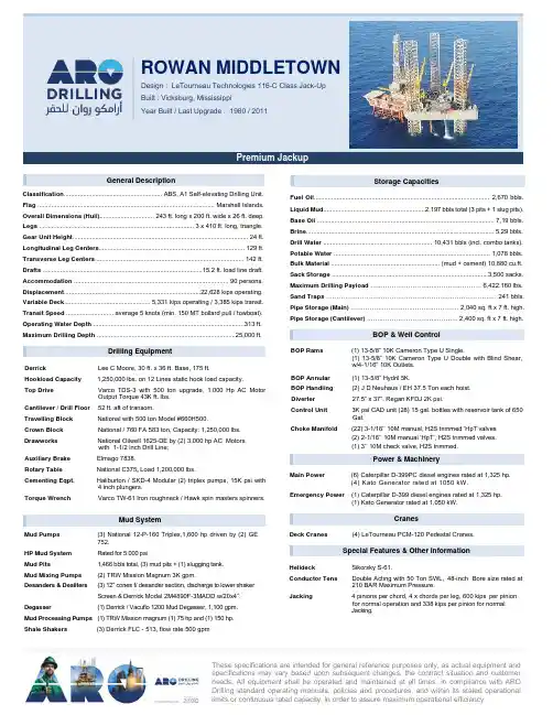
These specifications are intended for general reference purposes only, as actual equipment and specifications may vary based upon subsequent changes, the contract situation and customer needs. All equipment shall be operated and maintained at all times, in compliance with ARO Drilling standard operating manuals, policies and procedures, and within its stated operational limits or continuous rated capacity, in order to assure maximum operational efficiency.General DescriptionClassification ........................................................ ABS, A1 Self-elevating Drilling Unit. Flag ..................................................................................................... Marshall Islands. Overall Dimensions (Hull)............................... 243 ft. long x 200 ft. wide x 26 ft. deep. Legs ........................................................................................ 3 x 410 ft. long, triangle. Gear Unit Height .................................................................................................... 24 ft. Longitudinal Leg Centers ................................................................................... 129 ft. Transverse Leg Centers ..................................................................................... 142 ft. Drafts ...........................................................................................15.2 ft. load line draft. Accommodation ........................................................................................ 90 persons. Displacement ..............................................................................22,628 kips operating. Variable Deck ................................................. 5,331 kips operating / 3,385 kips transit. Transit Speed ........................... average 5 knots (min. 150 MT bollard pull / towboat). Operating Water Depth ......................................................................................313 ft. Maximum Drilling Depth ...............................................................................25,000 ft.Drilling EquipmentDerrick Lee C Moore, 30 ft. x 36 ft. Base, 175 ft.Hookload Capacity 1,250,000 lbs. on 12 Lines static hook load capacity.Top DriveVarco TDS-3 with 500 ton upgrade, 1,000 Hp AC Motor Output Torque 43K ft. lbs. Cantilever / Drill Floor 52 ft. aft of transom. Travelling Block National with 500 ton Model #660H500.Crown BlockNational / 760 FA 583 ton, Capacity: 1,250,000 lbs. Drawworks National Oilwell 1625-DE by (2) 3,000 hp AC Motorswith 1-1/2 inch Drill Line;Auxiliary Brake Elmago 7838.Rotary Table National C375, Load 1,200,000 lbs.Cementing Eqpt. Haliburton / SKD-4 Modular (2) triplex pumps, 15K psi with4 inch plungers. Torque Wrench Varco TW-61 Iron roughneck / Hawk spin masters spinners.Mud SystemMud Pumps (3) National 12-P-160 Triplex,1,600 hp driven by (2) GE 752.HP Mud System Rated for 5,000 psiMud Pits1,466 bbls total, (3) mud pits + (1) slugging tank. Mud Mixing Pumps (2) TRW Mission Magnum 3K gpm.Desanders & Desilters (3) 12” cones f/ desander section, discharge to lower shakerScreen & Derrick Model 2M4890F-3MADD w/20x4”. Degasser (1) Derrick / Vacuflo 1200 Mud Degasser, 1,100 gpm. Mud Processing Pumps (1) TRW Mission magnum (1) 75 hp and (1) 150 hp.Shale Shakers(3) Derrick FLC - 513, flow rate 500 gpmStorage CapacitiesFuel Oil .................................................................................................... 2,670 bbls. Liquid Mud ..........................................................2,197 bbls total (3 pits + 1 slug pits). Base Oil ..................................................................................................... 7,19 bbls. Brine ........................................................................................................... 5,29 bbls. Drill Water .............................................................. 10,431 bbls (incl. combo tanks). Potable Water ......................................................................................... 1,078 bbls. Bulk Material .............................................................. (mud + cement) 10,880 cu.ft. Sack Storage .........................................................................................3,500 sacks. Maximum Drilling Payload …………………………..………………… 6,422,160 lbs. Sand Traps ……………………………………………………………………… 241 bbls. Pipe Storage (Main) …………….…………..…………………. 2,040 sq. ft x 7 ft. high. Pipe Storage (Cantilever) …….……….……………..………. 2,400 sq. ft x 7 ft. high.BOP & Well ControlBOP Rams (1) 13-5/8” 10K Cameron Type U Single.(1) 13-5/8” 10K Cameron Type U Double with Blind Shear, w/4-1/16” 10K Outlets. BOP Annular (1) 13-5/8” Hydril 5K.BOP Handling (2) J D Neuhaus / EH 37.5 Ton each hoist. Diverter27.5” x 37”, Regan KFDJ 2K psi.Control Unit 3K psi CAD unit (28) 15 gal. bottles with reservoir tank of 650 Gal.Choke Manifold (22) 3-1/16’’ 10M manual, H2S trimmed ‘HpT’valves (2) 2-1/16’’ 10M manual ‘HpT’, H2S trimmed valves. (1) 3’’ 10M check valve, H2S trimmed . Power & MachineryMain Power (6) Caterpillar D-399PC diesel engines rated at 1,325 hp.(4) Kato Generator rated at 1050 kW.Emergency Power (1) Caterpillar D-399 diesel engines rated at 1,325 hp.(1) Kato Generator rated at 1,050 kW.CranesDeck Cranes(4) LeTourneau PCM-120 Pedestal Cranes.Special Features & Other InformationHelideck Sikorsky S-61.Conductor TensDouble Acting with 50 Ton SWL, 48-inch Bore size rated at 210 BAR Maximum Pressure.Jacking 4 pinions per chord, 4 x chords per leg, 600 kips per pinion for normal operation and 338 kips per pinion for normal Jacking.ROWAN MIDDLETOWNPremium JackupDesign : LeTourneau Technologies 116-C Class Jack-Up Built : Vicksburg, Mississippi Year Built / Last Upgrade : 1980 / 2011ROWAN MIDDLETOWN - 22These specifications are intended for general reference purposes only, as actual equipment andspecifications may vary based upon subsequent changes, the contract situation and customerneeds. All equipment shall be operated and maintained at all times, in compliance with ARO Drillingstandard operating manuals, policies and procedures, and within its stated operational limits orcontinuous rated capacity, in order to assure maximum operational efficiency.。
石油钻井作业规范手册第一章引言石油钻井作为石油勘探开发的重要环节之一,对于确保油田生产高效稳定具有重要意义。
为了规范石油钻井作业过程,提高工作效率,减少事故风险,特编写本手册。
第二章作业准备2.1 活动前的准备在开始进行石油钻井作业之前,必须进行全面的准备工作,包括但不限于:- 检查钻机及设备的状态,确保工作正常;- 检查钻具、井下工具及备件的完整性和适用性;- 建立有效的通信系统,确保井口与井下之间的联系畅通;- 制定详细的工作计划和方案,确保每一个作业步骤都得到合理安排。
2.2 环境保护要求在进行石油钻井作业时,应遵循环境保护的原则和法规,特别注意以下事项:- 预防钻井液、燃料和化学品泄漏,采取必要的防护措施;- 妥善处理钻井废弃物,遵循环境保护的要求;- 按照规定进行废水处理和废气排放;- 合理利用资源,尽量减少能源的浪费。
第三章井下作业3.1 钻井液管理钻井液是钻井过程中重要的工作液体,需遵循以下规范要求:- 选择适宜的钻井液类型和配方,确保其性能满足作业需求;- 定期检查钻井液的性能和污染情况,及时调整和更换;- 钻井液循环系统的运行要稳定,以确保井筒的清洁和有效冷却;- 钻井液的处理和回收应符合环境保护的要求。
3.2 钻具管理钻具的管理对于保证钻井作业安全和高效是至关重要的,应注意以下事项:- 钻具的选择和检查要符合规定标准,确保其完好无损;- 钻具运输、存放和使用过程中要避免损坏和污染;- 钻具的清洗、维修和保养要定期进行,确保其性能可靠;- 严格执行钻具的上下井作业流程。
第四章安全管理4.1 作业人员培训作业人员必须具备一定的技术和安全知识,特别是以下方面:- 钻井设备的操作和维护技能;- 应急救援和事故处理的能力;- 环境保护及作业规范的意识。
4.2 事故预防和应急处理严格按照规定的安全操作流程进行钻井作业,确保人员和设备的安全,同时做好应急预案,包括但不限于以下方面:- 针对可能发生的突发情况制订详细的应急预案;- 配备必要的安全设备和防护装备,如灭火器、急救箱等;- 进行应急演练,提高应对突发事件的能力。
油田钻井技术手册(文中所有数字均为示意,非规范数值)油田钻井技术手册第一章概述1.1 目的和范围本手册介绍了在油气田钻井中所需的技术知识和操作规程,旨在帮助钻井工程师及时准确地掌握钻井工艺和作业程序,有效提高钻井生产效率和工作安全。
1.2 适用条件本手册适用于在陆地和海洋油气田中进行的各种类型的钻井作业,包括常规井、增强井、水平井、多段式水平井、超深井和大角度井等。
1.3 组成和内容本手册共分为七章,分别介绍了钻井工程的各个环节:第二章钻机设备2.1 钻机选型2.2 钻机构造2.3 钻机参数2.4 钻机组件2.5 钻杆组合与下洞2.6 钻头的分类、选用和维护第三章钻井液3.1 钻井液的种类3.2 钻井液的组成与性能3.3 钻井液循环系统3.4 钻井液操作流程及处理第四章钻井工艺4.1 钻井方案设计4.2 钻井进度控制4.3 钻井过程中的事故处理4.4 钻井终止操作第五章地层工程学5.1 岩石力学基础5.2 水文地质基础5.3 地质结构变形规律5.4 岩石破裂与井眼稳定性第六章测井工艺学6.1 测井技术基础6.2 测井参数和仪器6.3 测井资料解释6.4 测井资料在钻井工作中的应用第七章钻井作业安全7.1 钻井作业安全规章制度7.2 钻井作业各环节操作注意事项7.3 紧急事故应急处置方法与措施7.4 钻井施工自动化控制及技术发展趋势第二章钻机设备2.1 钻机选型钻机是钻井作业中必不可少的设备之一,鉴于不同钻井工艺和钻井地质条件的要求,可根据如下因素选择不同型号和型式的钻机:(1)井深和井径(2)杆组合的长度和钻头的选用(3)地质构造和井壁稳定性(4)井口及井眼的样式(5)钻井工艺和作业要求2.2 钻机构造钻机通常由下列主要部件组成:(1)钻井台,用于承接钻杆负荷,并支持钻杆旋转和往下推进。
(2)井口装置,用于装卸钻杆和钻头。
(3)钻机动力系统,用于提供旋转和远程控制操作。
(4)冷却系统,用于降低机械和液压设备的运转温度。

钻井工程技术员工作手册钻井二公司技术室目录前言第一章钻井施工操作规程第一节导管施工作业规程第二节表层施工作业规程第三节钻表层水泥塞操作规程第四节 PDC钻头操作规程第五节钻进施工作业规程第六节接单根作业规程第七节直井防斜技术规程第八节起下钻作业规程第九节甩钻具操作规程第十节钻具探伤规程第十一节现场钻具转运、补缺、回收操作规程第十二节防卡技术规程第十三节钻井工程事故处理规程第十四节自浮电子单点测斜仪操作规程第十五节雨季施工作业规程第十六节冬防保温作业规程第二章落物事故的预防与处理第一节不规则落物的打捞第二节钻具(包括套管、油管)的断落处理第三节常规事故类型、部位、特征、预防及处理方法说明表第四节处理井下事故常用的钻柱结构第三章卡钻事故的预防与处理第一节粘吸卡钻第二节坍塌卡钻第三节砂桥卡钻第四节缩径卡钻第五节键槽卡钻第六节泥包卡钻第七节落物卡钻第八节干钻卡钻第九节水泥卡钻第十节卡钻处理一般过程第四章常用钻井工具数据表第五章常用计算公式前言钻井是一种隐蔽的地下工程,钻井时可能会遇到由于客观因素和人为因素造成的钻井复杂及事故,这就需要钻井工程技术人员能够及时识别钻井事故的征象,准确地判断事故的类别,正确果断采取措施,避免复杂及事故进一步恶化,形成恶性事故,导致全井报废。
此手册的编写主要从钻井施工操作规程、卡钻、井下落物的事故预防及处理、常用工具数据、公式等方面入手,简明扼要,便于掌握。
本手册可作为现场施工及常规工程事故复杂预防及处理参考书。
具体施工操作规程和复杂、事故处理的流程和程序,还要严格执行公司下发的文件。
第一章钻井施工操作规程第一节导管施工作业规程1 使用螺旋刮刀钻头进行导管施工1.1挖好上底 l.0m×l.0m、下底0.6m×0.6m、深0.5-1.0m的梯形坑。
1.2根据导管尺寸选用相应的钻头,钻至导管设计深度以上2.0—3.0m。
1.3将导管下入预钻井眼。
1.4方钻杆接托盘,托盘下接一根钻铤,将导管压至设计深度。
石油钻井工操作手册
石油钻井是一项复杂而精密的工作,需要操作人员具备丰富的经验和专业知识。
本操作手册旨在为石油钻井工提供必要的操作指导,以确保工作安全、高效进行。
1. 钻井前准备
在开始钻井作业之前,必须进行充分的准备工作。
首先,确保钻井设备完好无损,各个部件齐全。
其次,对井口进行检查,清除杂物和障碍物,确保井口通畅。
最后,准备好所有必要的工具和材料,包括扳手、钻头、钻杆等。
2. 钻井操作步骤
a) 将钻头降入井口,确保钻头与井壁垂直接触。
b) 启动钻井设备,逐渐增加转速,开始钻井作业。
c) 监控钻井进度和钻井液循环情况,确保钻井作业正常进行。
d) 定期检查钻头磨损情况,根据需要更换钻头。
e) 在钻到设计深度后,停止钻进,进行井眼清理和固井作业。
3. 安全注意事项
a) 确保操作人员穿戴好安全装备,如安全帽、防护眼镜等。
b) 操作时严格遵守操作规程,严禁违章操作。
c) 遇到突发情况时,立即停止钻井作业,并报告相关部门。
d) 定期检查钻井设备,确保设备正常运行。
4. 紧急处理措施
在钻井作业中,可能出现各种紧急情况,如井喷、设备故障等。
在这种情况下,操作人员应迅速采取相应的措施,包括关闭井口防喷装置、停止钻进、撤离现场等,以确保人身安全和设备完好。
总结:石油钻井工作是一项高风险的工作,需要操作人员具备丰富的经验和专业知识。
本操作手册提供了钻井操作的基本步骤、安全注意事项和紧急处理措施,希望可以为石油钻井工提供必要的指导,确保工作安全、高效进行。

1钻前准备 (3)1.1钻机安装 (3)1.1.1连接管线 (3)1.1.2钻台准备 (3)1.2清点材料 (3)1.2.1钻具: (3)1.2.2套管 (4)1.2.3处理剂 (4)1.2.4其它材料 (4)1.3设备试运转 (4)1.4组合钻具 (5)1.4.1清洗检查丈量钻具 (5)1.4.2钻具通径 (5)1.4.3连接钻具 (5)1.4.4连接钻头 (5)2入井管材和工具的丈量 (6)2.1钻具检查丈量要求 (6)2.2丈量工具的规定: (6)2.2.1钻具: (6)2.2.2钻井工具 (7)2.2.3套管: (11)2.2.4套管附件: (11)3工具的使用与管理 (12)3.1基本要求: (12)3.2钻台工具: (12)3.3装井口工具 (12)3.4甲板工具 (12)4各井段开钻前检查内容 (13)4.136″井眼 (13)4.226″井眼 (14)4.317‐1/2″井眼 (15)4.412﹣1/4″井眼 (16)4.59﹣7/8″井眼井眼 (17)4.68﹣1/2″井眼井眼 (18)4.76"井眼 (19)5钻井作业 (20)5.1作业基本数据记录 (20)5.1.1基本数据 (20)5.1.2钻机安装数据: (20)5.2钻进作业 (20)5.2.1基本要求: (20)5.2.2主要岗位的职责规定: (21)5.2.3操作要求: (22)5.3起下钻作业 (23)5.3.1起钻作业: (23)5.3.2钻具组合: (25)5.3.3下钻作业 (27)5.4循环泥浆 (29)5.5测斜 (30)5.6取芯作业 (31)5.7下套管 (32)5.7.1下套管作业安全措施指南 (32)5.7.2在下套管及套管内作业注意事项 (33)5.7.3下套管前准备: (34)5.7.4通井、调整泥浆: (35)5.7.5下套管作业: (35)5.8电测 (40)5.9固井 (40)5.10装井口 (42)5.10.1作业人员职责要求 (42)5.10.2割套管,装套管头,试压工作指南 (43)5.10.3套管卡瓦安装程序 (43)5.11试压 (44)5.11.1作业人员职责要求 (44)5.11.2防喷器、阻流管汇、固井管汇、立管管汇试压程序及注意事项 (45)5.12钻水泥塞 (47)5.12.1作业人员职责要求 (47)6演习规定 (49)6.1防喷演习规定: (49)6.2其他演习规定 (49)7复杂情况 (50)7.1基本要求 (50)7.2井漏: (51)7.3井涌 (51)7.4钻具的刺漏 (53)7.5挤水泥 (54)7.6断钻具 (54)7.7打捞作业 (54)8试油作业 (58)8.1刮管作业: (58)8.2射孔作业: (59)8.3组合和起下试油管串: (59)8.4测试作业: (59)8.5其它: (60)8.6试油期间安全操作规定 (60)9弃井或保留井口 (62)9.1了解弃井或保留井口的程序: (62)9.2检查弃井或保留井口的工具是否齐全、完好: (62)9.3弃井: (62)9.4保留井口: (62)9.5甩钻具: (62)9.6弃井作业操作与注意事项 (63)10交接班要求 (64)1钻前准备1.1钻机安装1.1.1连接管线井架安装到位,连接好以下管线:2根泥浆高压水龙带,2根固井管线,1根灌泥浆管线,泥浆返出管线弯头,另外还有海水,淡水管线,蒸汽管线。
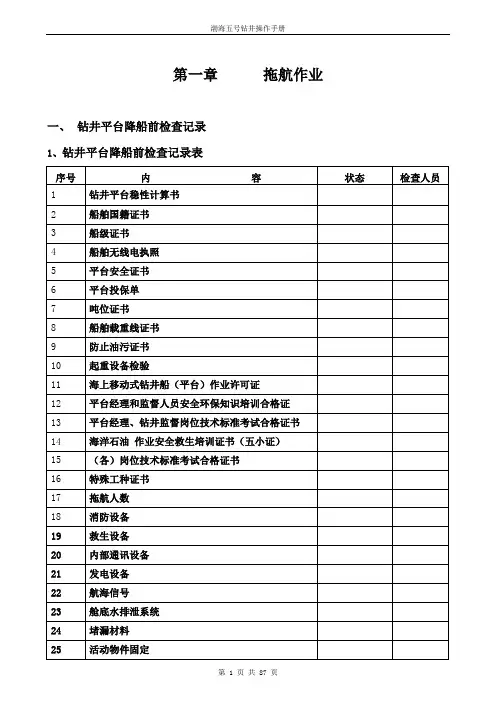
第一章拖航作业一、钻井平台降船前检查记录1、钻井平台降船前检查记录表2、钻井班及水手班拖航前检查记录表二、降船拖航作业1、降船前应做工作(1)关闭海底阀✧关闭所有泥浆池海底阀。
✧关闭泵舱海底阀。
✧关闭泥浆散装舱海底阀注意:1)关闭海底阀时要做渗漏试验。
2)海底阀的压盖要上紧。
3)关闭海底阀的工作有副司钻和水手(泥浆工)负责。
(2)活动物品固定✧大件物品可用角铁,电焊固定。
✧小件物品用钢丝绳,铁丝固定注意: 1)甲板风筒周围不能有任何活动物品。
2)不能在风筒、管线上固定任何物品。
3)甲板固定水手长负责,泵舱固定付钻负责。
(3)井架固定✧井架回推到位后,将底座与滑道的止动销插上。
井架底座与甲板的绷绳绷紧。
✧防喷器与其底座的所有固定螺栓要上紧,防喷器上部要用钢丝绳和手动倒链固定好。
✧游车大钩放到转盘面,用钢丝绳与转盘底座下的工字钢相连,上提游车5吨,将刹把刹死。
用钢丝绳和手动倒链将大钩与井架底座的四个角加以固定。
注意:1)游车,防喷器,井架底座固定必须确保固定质量。
2)钻台所有工具,设备都要仔细加以固定。
3)井架固定有司钻负责。
(4)关闭风筒✧关闭甲板上泵舱,灰罐舱风筒。
✧检查,关闭甲板所有舱室测量孔。
✧封闭甲板上舱室呼吸孔,舱盖。
注意: 1)舱室呼吸孔用塑料布或帆布封闭,舱盖用帆布封闭。
2)以上工作由水手长负责。
(5)检查冲桩管线✧由付钻关闭通向钻台的泥浆泵高压管线阀门,打开通向冲桩管线的阀门。
✧桩腿值班人员检查关闭桩箱上的冲桩管线阀门,检查保养冲桩管线软管接头。
准备好卸桩腿冲桩管线丝堵的工具。
✧桩腿值班人员打开桩室内冲桩边管线阀门。
(6)检查桩腿环形活动平台✧检查活动平台电机是否有电。
✧检查平台控制系统是否正常。
(7)上提潜水泵✧水手长协助轮机长上提潜水泵,水手长负责指挥吊车。
✧保留1台潜水泵工作,将其它潜水泵提到固定位置加以固定。
(8)带龙须链✧配合船舶拖轮带好龙须链。
注意吊龙须链的两台气动绞车钢丝绳松紧适度。
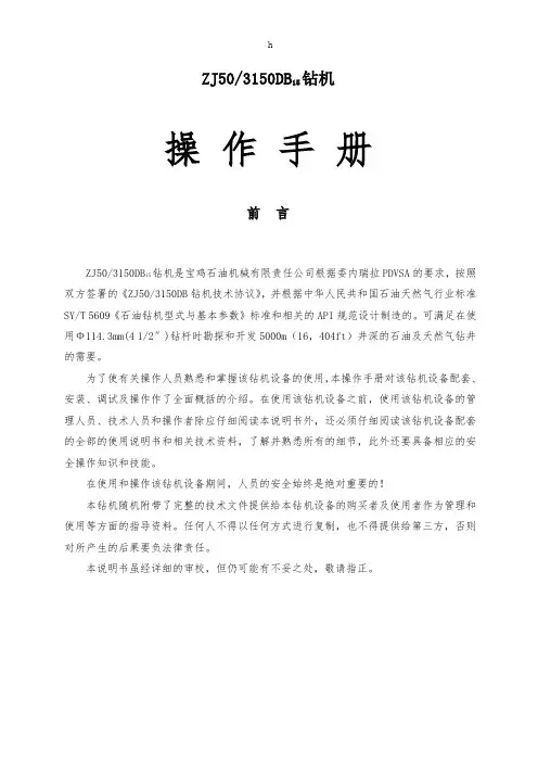
ZJ50/3150DB15钻机操作手册前言钻机是宝鸡石油机械有限责任公司根据委内瑞拉PDVSA的要求,按照ZJ50/3150DB15双方签署的《ZJ50/3150DB钻机技术协议》,并根据中华人民共和国石油天然气行业标准SY/T 5609《石油钻机型式与基本参数》标准和相关的API规范设计制造的。
可满足在使用Ф114.3mm(4 1/2″)钻杆时勘探和开发5000m(16,404ft)井深的石油及天然气钻井的需要。
为了使有关操作人员熟悉和掌握该钻机设备的使用,本操作手册对该钻机设备配套、安装、调试及操作作了全面概括的介绍。
在使用该钻机设备之前,使用该钻机设备的管理人员、技术人员和操作者除应仔细阅读本说明书外,还必须仔细阅读该钻机设备配套的全部的使用说明书和相关技术资料,了解并熟悉所有的细节,此外还要具备相应的安全操作知识和技能。
在使用和操作该钻机设备期间,人员的安全始终是绝对重要的!本钻机随机附带了完整的技术文件提供给本钻机设备的购买者及使用者作为管理和使用等方面的指导资料。
任何人不得以任何方式进行复制,也不得提供给第三方,否则对所产生的后果要负法律责任。
本说明书虽经详细的审校,但仍可能有不妥之处,敬请指正。
安全准则以下列出了与ZJ50/3150DB钻机设备密切相关的安全预防措施。
这些安全预防措施15在使用说明书以后的章节中不在出现。
在使用和维护该钻机设备的过程中,使用者必须掌握和运用这些推荐的预防措施。
具体的预防措施都包含在说明书的警示中。
1. 合格的人员只有被授权的合格人员才能操作和维护该钻机设备。
2. 防护设备操作和设施维护人员都必须穿戴防护服、防护帽、防护鞋及其它的防护设备等。
在钻井作业中,如遇有毒有害气体逸出,操作人员在作业时还必须配戴防毒设备。
3. 安全习惯安装、操作、拆卸和维护该设备时,好的全面的安全习惯必须随时遵守。
该钻机设备的拥有者/操作者的职责就是建立好的安全习惯、人员的培训和安全习惯的强制遵守。
钻孔操作指导书一、引言钻孔作为一项常见的地质勘探和建筑工程技术,广泛应用于地质勘察、土地开发、矿产勘探以及建筑物基础工程等领域。
本文档旨在为钻孔操作人员提供一份详细的操作指导,以确保钻孔过程的安全、高效和准确。
二、前期准备1. 确定钻孔位置:在进行钻孔前,需根据工程设计要求确定钻孔位置,标明坐标和孔深,并确认该位置不会对周围环境造成影响。
2. 准备钻孔设备:准备好所需的钻孔设备,包括钻机、钻杆、钻头、钻具、冲击钻等,并确保设备正常运行。
3. 检查地质资料:在进行钻孔前,仔细检查相关地质资料,了解地质情况和地层构造,以便根据实际情况调整钻孔操作。
三、钻孔操作步骤1. 设置钻孔机位:根据钻孔位置确定钻孔机位,确保钻机稳定、平整,并保持适当的角度。
2. 安装钻具:根据钻孔深度和地层情况,选择合适的钻具组合,并按顺序安装好钻杆和钻头。
在安装钻具时,需要确保各部件之间的连接牢固、紧密,并防止异物进入。
3. 启动钻孔机:启动钻孔机前,需要检查机器的各项指标是否正常,包括电力供应、液压系统、传动装置等。
启动钻孔机后,应根据钻孔设计要求,调整钻杆的转速和进给速度,确保钻孔操作的稳定性。
4. 开始钻孔:在开始钻孔前,需要通过冲击钻或慢速旋铤等方法,先行松动地层,为钻孔操作提供便利。
在钻孔过程中,需要密切观察钻具的状态和地层情况,及时调整钻孔机的参数,以保证钻孔的质量和效率。
5. 钻孔结束及取样:当达到预定的钻孔深度后,应立即停止钻孔操作。
在取出钻具时,应注意将地层样品完整地取下来,并进行标识和记录。
如果需要进一步分析和检测地层样品,应按规定方法进行取样和储存。
四、安全注意事项1. 钻孔过程中,操作人员应穿戴符合安全要求的防护装备,包括安全帽、护目镜、耳塞、防护鞋等。
2. 钻孔前要对钻具和钻机进行全面检查,确保设备运行正常,消除潜在的安全隐患。
3. 在操作钻孔机时,应注意保持身体平衡,确保操作过程中的稳定性。
4. 在钻孔过程中,应及时清除钻孔机周围的杂物,防止堵塞和危险情况的发生。
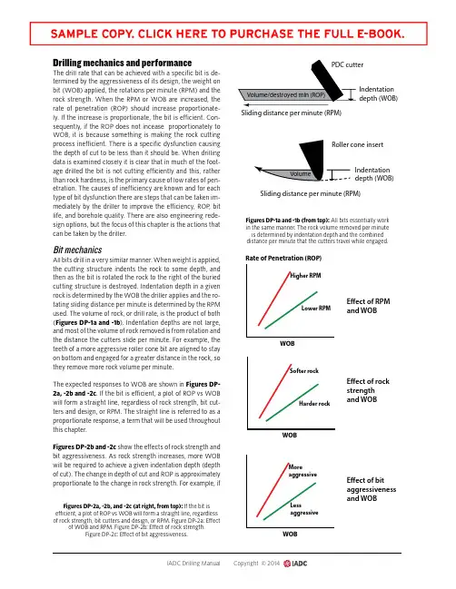
Drilling mechanics and performanceThe drill rate that can be achieved with a specific bit is de-termined by the aggressiveness of its design, the weight on bit (WOB) applied, the rotations per minute (RPM) and the rock strength. When the RPM or WOB are increased, the rate of penetration (ROP) should increase proportionate-ly. If the increase is proportionate, the bit is efficient. Con-sequently, if the ROP does not incease proportionately to WOB, it is because something is making the rock cutting process inefficient. There is a specific dysfunction causing the depth of cut to be less than it should be. When drilling data is examined closely it is clear that in much of the foot-age drilled the bit is not cutting efficiently and this, rather than rock hardness, is the primary cause of low rates of pen-etration. The causes of inefficiency are known and for each type of bit dysfunction there are steps that can be taken im-mediately by the driller to improve the efficiency, ROP, bit life, and borehole quality. There are also engineering rede-sign options, but the focus of this chapter is the actions that can be taken by the driller.Bit mechanicsAll bits drill in a very similar manner. When weight is applied, the cutting structure indents the rock to some depth, and then as the bit is rotated the rock to the right of the buried cutting structure is destroyed. Indentation depth in a given rock is determined by the WOB the driller applies and the ro-tating sliding distance per minute is determined by the RPM used. The volume of rock, or drill rate, is the product of both (Figures DP-1a and -1b ). Indentation depths are not large, and most of the volume of rock removed is from rotation and the distance the cutters slide per minute. For example, the teeth of a more aggressive roller cone bit are aligned to stay on bottom and engaged for a greater distance in the rock, so they remove more rock volume per minute.The expected responses to WOB are shown in Figures DP-2a, -2b and -2c . If the bit is efficient, a plot of ROP vs WOB will form a straight line, regardless of rock strength, bit cut-ters and design, or RPM. The straight line is referred to as a proportionate response, a term that will be used throughout this chapter.Figures DP-2b and -2c show the effects of rock strength and bit aggressiveness. As rock strength increases, more WOB will be required to achieve a given indentation depth (depth of cut). The change in depth of cut and ROP is approximately proportionate to the change in rock strength. For example, ifIndentation depth (WOB)Indentation depth (WOB)Sliding distance per minute (RPM)Figures DP-1a and -1b (from top): All bits essentially work in the same manner. The rock volume removed per minute is determined by indentation depth and the combined distance per minute that the cutters travel while engaged.Higher RPMLower RPMSofter rockHarder rockMoreaggressiveLessaggressiveWOBWOBWOBRate of Penetration (ROP)E ect of RPM and WOBE ect of rock strength and WOBE ect of bit aggressiveness and WOBFigures DP-2a, -2b, and -2c (at right, from top): If the bit is efficient, a plot of ROP vs WOB will form a straight line, regardless of rock strength, bit cutters and design, or RPM. Figure DP-2a: Effectof WOB and RPM. Figure DP-2b: Effect of rock strength.Figure DP-2c: Effect of bit aggressiveness.the rock strength increases by 10% the drill rate should be expected to decline by about 10%.The bit aggressiveness determines the indentation depth and torque that will occur for a given WOB. As shown in Fig-ure DP-2c, a more aggressive bit will drill faster because any given WOB will cause it to indent to a greater depth of cut (DOC) per revolution.When operating efficiently, rock strength and bit aggressive-ness effect the drill rate, but large changes in drill rate are usually due to inefficiency or dysfunction in the rock cutting process. If the bit is efficient, it is only necessary to raise the WOB or RPM in order to drill faster. If the bit is not cutting rock efficiently, the driller must identify and address the cause of dysfunction in order to significantly increase perfor-mance. The types of dysfunctions and the driller’s response will be discussed.If the increase in ROP is not proportionate to changes in WOB or RPM, something is interfering with the indentation depth. The poor response to WOB is referred to as bit founder. For example, Figure DP-3a shows the relationship the driller will observe between WOB and ROP for bit balling, which is one form of founder.As weight is initially applied, bits tend to be inefficient at very low loads. The efficiency increases as the weight is in-creased. In Figure DP-3a the bit has reached its peak effi-ciency at Point 1, and a proportionate response is seen at any WOB between Point 1 and Point 2. When the bit is efficient, increased performance only requires that the driller contin-ue to raise the WOB. Not only will the ROP increase, but it will also increase by the same amount for each incremental increase in WOB. The response is linear, proportionate and predictable. At Point 2, bit balling is beginning to occur, which interferes with the depth of cut. The bit becomes even less efficient if additional WOB is applied. Point 2 is referred to as the founder, or flounder point. The driller achieves peak per-formance by determining the WOB at which the bit founders and operating with a bit weight that is close to that point. The process of determining the founder WOB is repeated for var-ious rotary speeds.In the case of bit balling, it is also useful for the driller to con-duct step tests with the third parameter that he controls, which is flow rate. Whether flow rate has any effect on per-formance depends on the cause of bit dysfunction, but in-creased flow rate is almost always effective in increasing the founder point for bit balling.Once the driller goes through the process of identifying the founder point, parameters are used that keep the operation at or just below founder. Performance has been maximized and cannot be improved further unless the cause of ineffi-ciency is addressed and the founder point is increased to a higher WOB.Figure DP-3b shows what should occur to increase perfor-mance further. In the case of bit balling, for example, if pump horsepower is not already fully utilized, the driller can change the founder point by increasing the flow rate and nozzle fluid velocity. This keeps the bit clean to a higher depth of cut and drill rate. Founder will still occur, but at a higher WOB. In one field case, the founder point and achievable ROP were elevat-ed from 120 ft/hr to 500 ft/hr with the same bit when the bit hydraulics were improved.It might not be necessary for the driller to know why the bit is foundering to find the best current operating parame-ters. However, it is necessary to know the cause of founder in order to take the specific action required to significantlyROPWOB WOBFigures DP-3a, -3b (from left): shows a straight-line response of ROP to WOB, indicating an efficient bit up to the founder point. The driller must limit WOB to remain at or below the founder point. Figure DP-3b shows the result of changing real-time practices or design that elevate the founder point to a higher WOB. The WOB the driller can now apply without foundering is increased, as is the achievable ROP.improve the current limitations. For example, increasing the nozzle velocity will not improve performance if drillstring vibrations are causing bit inefficiency. Therefore, the driller must have the knowledge and ability to determine the root cause. The drill team’s ability to identify the root causes of rock-cutting dysfunction in real time has been greatly en-hanced by the digital data now collected and the manner in which it is processed and displayed on many rigs. There are specific actions the driller can take to improve bit efficien-cy for every cause of dysfunction, and many other design changes that can be made by engineering.Testing bit performanceMost performance tests take the form of some type of step test. An example step test for determining inefficiency is shown in Figure DP-4a . In this case, the driller increases the WOB by 5,000 lb and the drill rate increases by 25 ft/hr. If the bit is efficient, the next 5,000 lb should yield another 25 ft/hr increase. If the drill rate increases by less than 25 ft/hr after the next step in WOB, the response is not propor-tionate. The increased weight has caused some form of rock cutting dysfunction (founder). While the drill rate has still increased, the bit has become less efficient. ROP will usually increase with WOB, but if the increase is not proportionate, something is wrong. The drilling performance is less than it should be, and the dysfunction might also be damaging to the bit. The same step test process can be applied when changing RPM. Increase RPM in fixed steps (i.e., 5 rpm), and ROP should increase proportionately and by the same amount with each step.As long as a proportionate response is seen from step to step, increased performance only requires that the driller continue to increase WOB or RPM to drill faster, and also to avoid damaging the bit or BHA. It is important that each stepin WOB or RPM be exactly the same. If the bit is efficient, a proportionate response will yield exactly the same increase in ROP, which is easy to see. If the steps are not exactly the same, the data can still be used, but the driller must physical-ly plot the ROP to see if the response plots as a straight line, as shown in Figure DP-4b . Using identical steps eliminates the need for plotting; it is only necessary to see that the ROP change is the same with each fixed step in WOB to know that the response is proportionate (straight line).If a downhole motor is being used, the same WOB step tests are conducted, but the motor differential pressure may also be used to observe a proportionate response, rather than just ROP. If the differential rises proportionately with each in-crease in WOB, the bit is efficient. If the pressure response is less than proportionate, the rock-cutting process is becom-ing inefficient.Drill-off testing is a method developed in the 1950s to min-imize the time to determine performance at various WOBs (Figure DP-5). The process works well with roller cone bits at moderate to low drill rates, but it tends to be less effec-tive with PDC bits. The driller applies a high WOB, locks the top-drive position, and continues rotation. The rotating bit drills ahead and the locked string elongates, transferring the drillstring weight that had been applied to the bit back to the hook. The amount of drillstring elongation is called “stretch”. The rate at which the hookload increases then provides an indication of how fast the string is elongating, which is also the bit drill rate .In the following example, the driller is recording the time re-quired for each additional 3,000-lb increase in hookload to occur, which corresponds to a 3,000-lb decrease in bit load. The ROP can be calculated and plotted during each incre-D e p t hWOB (K lbs)WOB (K lbs)ROP (ft/hr)R O P (f t /h r )510152025905101520253085755025Founder pointFigures DP-4a and -4b (from left): In Figure DP-4a, : WOB is increased in 5,000-lb steps, and ROP responds by increasing 25 ft/hr with each step, up to 20,000 lb. Between 15,000-20,000 lb the bit founders, and the next increase in ROP is less than 25 ft/hr (10 ft/hr). If the driller were to plot the average ROP at each WOB from the test in Figure DP-4a, it would produce the curve shown in Figure DP-4b. Founder isthe point at which the data is no longer a straight line (non-linear response).ment by the string stretch equation shown below. Stretchconstants for API DP may be found in reference manuals.DP Stretch= (Stretch Constant for specific DP)*(DP Length)*(Step Change in WOB) Eq 1Where units are:DP Stretch, in.;Stretch Constant, (in./k lb)/k-ft;DP Length, k ft; Step Change, k lb“k” indicates thousandsROP = (DP Stretch/Time)*[(3,600 sec/hr)/12 in./ft)Where units are:ROP, ft/hr;DP Stretch, in.;Time, secThe advantage of plotting data is to document the results andallow it to be communicated offsite. If documentation is notneeded, drillers usually conduct the test by simply observingthe time required for each increment of weight to drill off andthen using the WOB corresponding to the fastest time. In thisexample, the fastest drill rate would be seen at a WOB cor-responding to the 11- or 12-sec drill-offs (positions number 2and 3 in Figure DP-5).Mechanical Specific Energy (MSE) surveillance is anothermethod for determining drilling performance. Drill-off testsare well suited to roller-cone bits, intermediate drill stringlengths with significant stored stretch, and bit balling. But theprocedure does not produce clear results with PDC bits thatdrill with very light WOB, because the weight may drill offbefore meaningful data can be collected. Also, complex vi-brations tend to dominate bit dysfunction with PDC bits. Forthese reasons, surveillance practices have been developed inrecent years to continuously plot the amount of work the bitis doing, and this value shows whether the bit is becomingmore or less efficient as changes are made in parameters.Mechanical Specific Energy is the work or energy being usedper volume of rock drilled. MSE is plotted by the data-acqui-sition computer alongside other drilling data, such as WOB,RPM and ROP. In theory, if the bit is perfectly efficient, thevalue of the MSE equals the rock strength in psi. But in fieldpractice, it is primarily used as a relative indicator and it isnot necessary to know the rock strength. The driller makes achange and observes the MSE to see if rock cutting efficiencyimproved or declines.Figure DP-6 shows an MSE curve from a well in which bitballing is occurring. The footage where the MSE is high in-dicates that there is dysfunction (in this case, bit balling).When the bit drilled from a shale back into a sand, the MSEfell, indicating the bit’s cutting structure has cleaned up andis now operating efficiently. Changes in rock hardness alsoaffect the energy required, but this is minor when comparedto the energy increase when bit dysfunction occurs, so theselarge changes in MSE are very useful in showing dysfunction.When combined with other information, it can also be usedto determine the cause of the problem.Chasgnes in MSE can be related to effects of dysfunctionshown in Figure DP-7. If the MSE increases when a changeis made, the performance is moving further way from the ef-ficient performance, which would be the dashed blue line. Ifit decreases, the performance is moving closer to the dashedline. For example, the curve for whirl shows that if WOB is in-creased, the ROP performance moves closer to the predictedline, which means that inefficiency due to whirl is decreasing,and we would expect the MSE to go down. This is used as aCalculated weight on bitCalculated R OP(3) 12 sec, 109 k #(4) 15 sec, 112 k #(5) 17 sec, 109 k #Figure DP-5: Drill-off test conducted by observing the time required to drill off 3,000-lb increments of weight on bit. The highest ROP occursat the WOB corresponding to the shortest required time per increment.diagnostic. If the WOB is increased, and the MSE declines, we know that whirl was the cause of dysfunction to start with. As shown in Figure DP-7, there is no other dysfunction that improves as WOB is increased (e.g., moves closer to the dashed line). In order to identify some of the other forms of founder, it is necessary to observe additional data, or to have more information about the drilling conditions. This is dis-cussed in the sections below.Regardless of the cause of dysfunction, the manner in which the driller uses the MSE to maximize real time performance is the same. To get this performance, the driller must conduct step tests by changing one parameter at a time (WOB, RPM or GPM).If the MSE declines the dysfunction is getting better and performance is improving. Continue with more of thesame change (i.e., even higher WOB);If the MSE increases, the dysfunction is becoming worse and performance is declining. Change theparameter in the other direction (i.e., reduce the WOB); If the MSE stays the same performance is on the straight line portion of the drill off curve in FigureDP-3a. Continue increasing WOB to founder.It should be emphasized that the driller cannot simply ob-serve the MSE curve and diagnose most root causes, or de-termine the next action. Step tests must be conducted, and the MSE response to the change observed. It is the response that is diagnostic.Causes of drilling dysfunctionsEach of the categories of bit dysfunction will be discussed, as well as the observations that can be made to diagnose what is occurring in real time. The corrective actions that can be taken immediately at the rig site will also be dis-cussed. Figure DP-7 shows the effect that each of the major forms of dysfunction may have on ROP as WOB is increased. At any given point in time only one of these usually domi-nates. However, this is not always true and that can com-plicate diagnosis. The types of rock cutting dysfunction dis-cussed are:Bit balling: buildup of material on the bit that interferes with depth of cut;Interfacial severity: formations with hard inclusions or layers that cause axial shocks and break cutters;Bottomhole balling: layer of ground cuttings held to the bottom of the hole by differential pressure;Whirl vibrations: lateral motion of the string and bit;Stick-slip vibrations: torsional motion in which the bit speed oscillates periodically;Axial vibrations: axial motion in which the bit depth of cut oscillates periodically.The flow chart in Figure DP-8 summarizes a progression of activities to maximize performance. There are five forms of dysfunction shown and the driller’s response to each. There are also numerous engineering redesign options, but these are not within the scope of the chapter. The flow chart is not self-explanatory and the dysfunctions, testing procedures and responses are contained in the detailed discussions to follow.Bit ballingBit balling occurs when drilled material accumulates on the cutting structure that begins to carry some of the applied WOB, so that the weight on the cutter tips is reduced. Con-Causes and e ects of founderE cient bitw/expected DOCRate of penetration (ROP)Bit ballingWhirlStick-slipInterfacial severityBottomhole ballingWOBFigure DP-6: Example Mechanical Specific Energy (MSE) plot showing severe bit dysfunction in shales due to bit balling and efficient drilling in sands. Nozzles were changed during a trip to increase bit cleaning and the MSE curve now shows both shales andsands drilling efficiently.Figure DP-7: Founder, or rock-cutting dysfunction, causes the depth of cut and ROP to be less than it should be for a given WOB, causing performance to decline. The order in which the various dysfunctions are seen as WOB is increased will vary and must be determined bythe driller in an organized step test.。
钻井事业部半潜式平台井控操作手册2004年2月一. 主要人员的职责 (2)二. 关井方式 (3)三. 关井程序 (4)特殊关井程序: (4)常规关井程序: (4)(一)钻进时关井的方法 (4)(二)起下钻时关井的方法 (4)(三)起下钻铤时关井的方法 (5)(四)空井时关井的方法 (6)(五)电测时关井的方法 (6)(六)下套管时关井的方法 (6)四. 压井方法 (7)五.井控计算表格 (8)附:关井钻杆位置计算 (12)一、主要人员的职责(一)、平台高级队长1.接到井控报告,立即按响井喷警报,负责组织钻井平台各岗位人员按井喷应急处置方案和指令行动。
2.负责向岸基应急中心报告现场情况,接受并执行指令。
3.立即停止所有明火作业(包括香烟)。
4.让报务员通知守护船到平台上风指定区域待命并直到需要协助撤离平台人员;5.当情况危及平台和工作人员的人身安全时,同钻井总监协商后发布弃船命令,弃船时负责指挥平台人员的撤离工作。
6.当形势很严重时,命令所有不参与井控操作和平台操作的人员撤离平台到守护船去。
7.指令作业人员做好推进器的备机准备,关闭不必要的通风;8.指令作业人员做好锚机的备机准备;9.井控结束后,通知平台人员危险解除。
10.应急处理过程中应始终与钻井总监保持密切联系。
(二)、值班队长1.组织、指挥井口操作人员按照钻井总监指令进行作业。
2.指派人员负责倒换立管和阻流管汇阀门并亲自复查确认。
3.正确记录井喷/井涌和压井过程中的相关数据。
4.对作业过程中有疑问的数据或程序及时同钻井总监沟通和确认。
(三)、司钻1.发现有井涌或井喷情况应立即通知钻井总监。
2.坚守钻台司钻岗位,准确判断井下情况,迅速控制井口。
3.组织本班人员严格按钻井总监指令进行作业并收集井喷有关资料。
(四)、副司钻1.坚守泵舱岗位,作好循环排气和压井准备。
2.确保泵舱的设备、管线等处于良好的工作状态。
(五)、井架工1.负责井架上的操作。
2.负责观察防喷器的压力变化及套管头的密封情况。
石油钻井操作手册第一章操作手册简介本操作手册是为石油钻井操作人员编写的指南,旨在提供详细的操作流程和步骤,以确保钻井作业的安全性和效率性。
操作手册涵盖了井口设备安装、钻井液配制、钻井工具使用、井下操作等多个方面的内容。
第二章前期准备2.1 设备检查2.1.1 井口设备检查:检查井口设备的完整性和工作状态,包括钻井井口防喷器、接头、套管头、井口护栏等。
2.1.2 钻机设备检查:检查钻机的工作状态,包括悬挂系统、旋转系统、钻杆系统、钻具及附件等。
2.2 环境保护2.2.1 确保钻井液准备符合环保要求。
2.2.2 做好废弃物处理和污水处理的准备工作。
第三章井口设备安装3.1 钻完井作业前的井口设备安装3.1.1 安装钻井井口防喷器:根据工作需要选择合适的防喷器,并按照操作手册的指导进行安装。
3.1.2 安装钻井接头:确保接头与井口设备的连接牢固可靠,并进行必要的密封处理。
3.2 井下设备安装3.2.1 安装钻具:根据井深和作业需求选择合适的钻杆、钻铤等钻具,并按照操作手册的指导进行安装。
3.2.2 安装钻井工具:根据作业需求选择合适的钻井工具,如扩径钻头、钻眼下套等,并按照操作手册的指导进行安装。
第四章钻井液配制4.1 钻井液配方设计4.1.1 根据井段情况和作业要求确定钻井液的密度、粘度、过滤性能等参数。
4.1.2 选择适当的添加剂,并按照操作手册的指导进行配置。
4.2 钻井液搅拌4.2.1 根据配方要求将水和添加剂注入搅拌池。
4.2.2 启动搅拌设备进行充分搅拌,确保钻井液的均匀性和稳定性。
第五章钻井作业5.1 下井准备5.1.1 确保井口设备安装完毕,并进行必要的检查和测试。
5.1.2 确保钻井液准备就绪,包括密度、粘度等参数符合要求。
5.2 钻井操作5.2.1 钻具下井:使用井下钻井工具将钻具下入井内。
5.2.2 钻井液循环:启动钻井泵进行钻井液的循环,确保井内保持适当的压力和稳定的循环流量。
第二章钻前准备一.移井架1.解除井架固定1)松开井架绷绳。
2)拔出井架底座止动销。
3)清除井架底座滑道障碍物,并在滑道上涂抹少量钻杆丝扣油。
注意:➢绷绳花杆螺栓卸下后要保养好,放入桩箱内。
➢仔细检查井架与非移动部位连接的空气管线。
➢由司钻负责安排。
2.移井架1)移井架时井架两侧有专人值班,防止井架偏移及挂管线。
2)气测平台有电工看护电缆桥,以防损伤电缆桥或挤坏电缆。
3)井架移到位且不再调节井口后液压缸收回,固定井架底座,井架底座滑道盖盖板,清理控制台卫生,爬行爪销子保养。
注意:井架发生偏斜时,要及时调正,防止撞坏甲板支撑筋板。
3.连接管线井架移至钻井位置,连接好以下管线:2根泥浆高压水龙带,2根固井管线,1根灌泥浆管线,泥浆返出管线弯头,另外还有海水,淡水管线,蒸汽管线。
注意:蒸汽管线在冬季连接,由机工负责,其它管线由钻井班负责。
4.钻台准备1)解除钻台所有固定,检查转盘地角螺丝。
2)试车,同时准备连接校正井口及开眼钻具的井口工具:A.5”DP吊卡、5”钻杆卡瓦、3#补心;B.8”DC吊卡,钻铤提升器、8”钻铤卡瓦、安全卡瓦(11片);C.9”DC吊卡、钻铤提升器、9”钻铤卡瓦、安全卡瓦(12片)、2#补心&SDD大钳及相应钳头;D.26”钻头盒及钻头上卸扣器;E.各种配合接头及提丝。
3)接1柱8”DC,校正井口。
要求:➢内钳甲检查钻机保养及冷却系统。
外钳甲检查钻台压缩空气、气动绞车、旋扣钳及各种钻井工具。
架工负责检查井架滑轮、猴台、二层台指粱及小气动绞车、安全带等。
➢付钻负责钻台阻流管汇、立管管汇阀门处于正确状态,检查各泥浆管线处于正确连接。
➢付钻负责泵舱泥浆泵,泥浆管线阀门处于正确状态。
➢升船结束后,泥浆工检查固控设备,泥浆返出管线各闸门处于正确位置;检查输灰管线闸门及配浆系统;检查泥浆池搅拌机运转情况;泥浆池、散装舱的海底门打开到位,让机工开启低压压风机,检查所有气管线闸门;输入般土粉及加重材料,准备配置高粘般土浆。
第一部分:接头第二部分:钻井工具第三部分:开钻完井处理事故工具第四部分:钻具第五部分:钻头第六部分:井口装置第七部分:钻井设备第八部分:计算公式第九部分:附录第十部分:井控技术第十一部分:钻井工艺一.接头分类及尺寸API钻杆加厚端(钻杆管体与钻杆接头的连接处)加厚形式的不同从而粗牙螺纹端产生了内平,贯眼,正规三种类型的接头( 后又出现了数字型)●API钻杆加厚端如下示:钢级内加厚(IU) 外加厚(EU) 内外加厚(IEU)━━━━┓┏━┓┏━┓D,E ──┐..┃━━━━┛..┃━━━━┛..┃└─┨──────┨───┐....┃┌─┨──────┨└──┨──┘..┃━━━━┓..┃┌──┨━━━━┛┗━┛───┘....┃━━┓..┃┗━┛━━━━┓┏━┓┏━━┓┐..┃━━━━┛..┃━━━┛....┃└─┨───┐....┃───┐....┃X, G, S ┌─┨└──┨└──┨──┘..┃┌──┨┌──┨━━━━┛───┘....┃───┘....┃━━┓..┃━━━┓....┃┗━┛┗━━┛●API:1.内平接头(IF)主要用于EU,IEU钻杆,钻杆加厚处内径=接头内径=管体内径2.主要用于IU,IEU钻杆,钻杆加厚处内径=接头内径<管体内径3.正规接头(REG)主要用于IU钻杆,接头内径<加厚部分内径<管体内径●NC: 4.数字型接头新型糸列,逐渐取代API标准中全部IF和除5 1/2"FH的全部FH 接头,有几种与旧API接头可互换,主要有NC50-2 3/8"IFNC38-3 1/2"IF ,NC40-4"FH ,NC46-4"IF, NC50-4 1/2"IF.1┏━━━━┯━━━━┯━━━━━┯━━━━━┯━━━━━━┓┃螺纹代号│牙型代号│公扣根部D │公扣小端d │母扣外端内径┃┠────┼────┼─────┼─────┼──────┨┃ NC23 │V-0.038R│ 65 │ 52 │ 67 ┃┃ NC26 ││ 73 │ 60 │ 75 ┃┃ NC31 ││ 86 │ 71 │ 88 ┃┃ NC35 ││ 95 │ 79 │ 97 ┃┃ NC38 ││ 102 │ 85 │ 104 ┃┃ NC40 ││ 109 │ 90 │ 110 ┃┃ NC44 ││ 118 │ 99 │ 119 ┃┃ NC46 ││ 123 │ 104 │ 125 ┃┃ NC50 ││ 133 │ 114 │ 135 ┃┃ NC56 ││ 149 │ 118 │ 151 ┃┃ NC61 ││ 164 │ 129 │ 165 ┃┃ NC70 ││ 186 │ 148 │ 187 ┃┃ NC77 ││ 203 │ 162 │ 205 ┃┠────┼────┼─────┼─────┼──────┨┃23/8"REG│ V-0.04 │ 67 │ 48 │ 68 ┃┃27/8"REG││ 76 │ 53 │ 78 ┃┃31/2"REG││ 89 │ 65 │ 91 ┃┃41/2"REG││ 118 │ 91 │ 119 ┃┃51/2"REG│ V-0.05 │ 140 │ 110 │ 142 ┃┃65/8"REG││ 152 │ 131 │ 154 ┃┃75/8"REG││ 178 │ 145 │ 180 ┃┃85/8"REG││ 202 │ 168 │ 204 ┃┠────┼────┼─────┼─────┼──────┨┃3 1/2"FH│ V-0.04 │ 102 │ 78 │ 103 ┃┃4" FH│V-0.065 │ 109 │ 90 │ 110 ┃┃4 1/2"FH│ V-0.04 │ 121 │ 96 │ 124 ┃┃5 1/2"FH│ V-0.05 │ 148 │ 127 │ 150 ┃┃6 5/8"FH│ V-0.05 │ 172 │ 150 │ 174 ┃┠────┼────┼─────┼─────┼──────┨┃2 3/8"IF│V-0.065 │ 73 │ 60 │ 75 ┃┃2 7/8"IF││ 86 │ 71 │ 88 ┃┃3 1/2"IF││ 102 │ 85 │ 104 ┃┃4" IF││ 123 │ 104 │ 104 ┃┃4 1/2"IF││ 133 │ 114 │ 135 ┃┃5 1/2"IF││ 163 │ 141 │ 164 ┃┗━━━━┷━━━━┷━━━━━┷━━━━━┷━━━━━━┛二.常用钻具扣型及内┏━━━━━━━━┯━━━━┯━━━━━┓┃外径尺寸(in/mm) │内径(mm)│扣型┃┠────────┼────┼─────┨┃ 9"(229) │ 76 │ 731X730 ┃┃ 8"(203) │ 76 │ 631X630 ┃┃ 7"(178) │ 76 │ 411X410 ┃┃ 6 1/2"(164) │ 57.15 │ 411X410 ┃┃ 6 1/4"(159) │ 71.44 │ 4A1X4A0 ┃┃││(421X420) ┃┃ 5 3/4"(146) │ 57.15 │ 421X420 ┃┃ 5"(127) │ 108.6 │ 411X410 ┃┃ 3 1/2"(89) │ 38.1 │ 311X310 ┃┃ 2 7/8"(73) ││ 211X210 ┃┃ 2 3/8"(60) ││ 211X210 ┃┗━━━━━━━━┷━━━━┷━━━━━┛常用打捞工具扣型 6 1/2"随钻411X410 200打捞杯4A0(上)X4A1(下)Φ200牙轮打捞器410(4 1/2"IFΦ200强磁打捞器410(4 1/2"IFΦ200高效打捞杯磨鞋410(4 1/2"IF)三.钻头扣型┏━━━━━━┯━━━━━━┯━━━━━━━┯━━━━━━┓┃钻头直径│接头丝扣尺寸│钻头直径│接头丝扣尺寸┃┃ mm in │ in │ mm in │ in ┃┠──────┼──────┼───────┼──────┨┃95.2 3 3/4"│ 2 3/8"REG │215.6 8 1/2" │ 4 1/2"REG ┃┃98.4 3 7/8"│ (231) │222.2 8 3/4" │┃┃│├───────┼──────┨┃104.8 4 1/8"││241.3 9 1/2" │ 6 5/8"REG ┃┃107.9 4 1/4"││244.5 9 5/8" │ (631) ┃┠──────┼──────┤│┃┃111.1 4 3/8"│ 2 7/8"REG │250.8 9 7/8" │┃┃117.5 4 5/8"│ (231) │ 254.0 10.0" │┃┃120.6 4 3/4"││269.9 10 5/8"│┃┠──────┼──────┤│┃┃130.2 5 1/8"│ 3 1/2"REG │ 279.4 11" │┃┃142.9 5 5/8"│ (331) │295.3 11 5/8"│┃┃149.2 5 7/8"││311.1 12 1/4"│┃┃ 152.4 6 " ││346.0 13 5/8"│┃┃155.6 6 1/8"││342.9 13 1/2"│┃┃│├───────┼──────┨┃158.7 6 1/4"││374.6 14 3/4"│ 7 5/8"REG ┃┃165.1 6 1/2"││393.7 15 1/2"│ (731) ┃┃171.4 6 3/4"││445.5 17 1/2"│┃┃174.6 6 7/8"││ 508.0 20" │┃┠──────┼──────┤│┃┃190.5 7 1/2"│ 4 1/2"REG │ 609.6 24" │┃┃200.0 7 7/8"│ (431) │ 660.4 26" │┃┃212.7 8 3/8"│││┃┗━━━━━━┷━━━━━━┷━━━━━━━┷━━━━━━┛四.接头术语缩语REG 正规扣 FH 贯眼扣 IF 内平扣NC 数字型 OH 开眼型 SH 小眼型WO 轻便型(加大内平)MO 修正加大贯眼型DSL 双流型SL-H-90 小井眼术语休斯90度螺纹H-90 休斯90度螺纹 EH,XH 加大贯眼型PAC V-0.076螺纹IU 内加厚 EU 外加厚 IEU 内外加厚联顶节长度┏━━━━━━┯━━━━━┯━━━━━┯━━━━━┓┃钻机│13 3/8表层│9 5/8中完│5 1/2完井┃┠──────┼─────┼─────┼─────┨┃大庆I--130 │ 4.46 │ 4.32 │ 3.96 ┃┠──────┼─────┼─────┼─────┨┃大庆I-130高│ 5.97 │ 5.87 │ 5.66 ┃┠──────┼─────┼─────┼─────┨┃大庆Ⅱ -130 │ 4.76 │ 4.67 │ 4.28 ┃┠──────┼─────┼─────┼─────┨┃ ZJ--45 │ 5.77 │ 5.64 │ 5.46 ┃┠──────┼─────┼─────┼─────┨┃ F--320 │ 7.97 │ 7.84 │ 7.55 ┃┠──────┼─────┼─────┼─────┨┃车--750 │ 5.77 │ 5.64 │ 5.46 ┃┠──────┼─────┼─────┼─────┨┃σY--40 │ 3.97 │ 3.84 │ 3.46 ┃┗━━━━━━┷━━━━━┷━━━━━┷━━━━━┛( 注:长度包括接箍)入井接头,联顶节钢级,壁厚┏━━━┯━━━┯━━━━━┯━━━━━━┯━━━━━━┓┃种类│尺寸│钢级│壁厚│备注┃┃│ in ││ mm │┃┠───┼───┼─────┼──────┼──────┨┃接头││ 35GrMo ││ GrMo-铬┃┃││ 40GrMo ││┃┠───┼───┼─────┼──────┼──────┨┃│ 5 │ P110 │9.19 │ GrMo-钼┃┃├───┼─────┼──────┼──────┨┃│5 1/2 │P110 │10.54 │套管接箍一般┃┃联├───┼─────┼──────┼──────┨┃│7 │P110 N80 │10.36 12.65 │J55-绿接箍┃┃├───┼─────┼──────┼──────┨┃顶│8 3/8 │N80 │10.16 11.43│N80-红接箍┃┃├───┼─────┼──────┼──────┨┃│9 5/8 │P110 N80 │10.06 11.19│P110-白接箍┃┃节├───┼─────┼──────┼──────┨┃│10 3/4│N80 │11.34 │┃┃├───┼─────┼──────┼──────┨┃│13 3/4│J55 │12.19 │┃┗━━━┷━━━┷━━━━━┷━━━━━━┷━━━━━━┛钻杆吊卡┏━━━━━┯━━━━━┯━━━━┯━━━━━━━━┓┃规格型号│孔径│额定负荷│钻杆规格┃┃├──┬──┼────┼────┬───┨┃│上孔│下孔│ t │配用钻杆│ mm ┃┠─────┼──┼──┼────┼────┼───┨┃CDK-63*69 │69 │63 ││2 3/4EU │ 60.3 ┃┠─────┼──┼──┤ 150 ├────┼───┨┃CDK--76*84│84 │76 ││2 7/8EU │ 73.0 ┃┠─────┼──┼──┼────┼────┼───┨┃" 92*102 │102 │92 ││3 1/2EU │88.90 ┃┠─────┼──┼──┤├────┼───┨┃" 105*109 │109 │105 │ 200 │4IU │101.6 ┃┠─────┼──┼──┤├────┼───┨┃" 105*118 │118 │105 ││ 4EU │ " ┃┠─────┼──┼──┼────┼────┼───┨┃" 118*122 │122 │118 ││4 1/2IU │114.3 ┃┃─────┼──┼──┤ 250 ├────┼───┨┃" 118*131 │131 │118 ││4 1/2EU │114.3 ┃┠─────┼──┼──┼────┼────┼───┨┃" 131*134 │134 │131 ││5 IEU │ 127 ┃┠─────┼──┼──┤ 350 ├────┼───┨┃" 144*144 │144 │144 ││5 1/2IU │139.7 ┃┗━━━━━┷━━┷━━┷━━━━┷━━━━┷━━━┛注:IU--内加厚 EU--外加厚 IEU--内外加厚2油管吊卡┏━━━━━━━━┯━━━━━┯━━━━┯━━━━━━━━━┓┃│││油管外径┃┃规格型号│孔径 mm │额定负荷├───┬─────┨┃││ t │ in │ mm ┃┠─┬──────┼─────┼────┼───┼─────┨┃│BDK--50/30 │ 50 ││1.9 │ 48.3 ┃┃├──────┼─────┤ 30 ├───┼─────┨┃│ " -56/30 │ 56 ││1.9EU │ 54 ┃┃单├──────┼─────┼────┼───┼─────┨┃│ " -63/50 │ 63 ││2 3/8 │ 60.3 ┃┃├──────┼─────┤├───┼─────┨┃│ " -68/50 │ 68 ││23/8EU│ 65.9 ┃┃├──────┼─────┤├───┼─────┨┃│ " -76/50 │ 76 │ 50 │2 7/8 │ 73 ┃┃├──────┼─────┤├───┼─────┨┃│ " -82/50 │ 82 ││27/8EU│ 78.6 ┃┃├──────┼─────┤├───┼─────┨┃│ " -92/50 │ 92 ││3 1/2 │ 88.9 ┃┃├──────┼─────┼────┼───┼─────┨┃头│ " -76/75 │ 76 ││2 7/8 │ 73 ┃┃├──────┼─────┤├───┼─────┨┃│ " -82/75 │ 82 ││27/8EU│ 78.6 ┃┃├──────┼─────┤├───┼─────┨┃│ " -92/75 │ 92 │ 75 │3 1/2 │ 88.9 ┃┃├──────┼─────┤├───┼─────┨┃│ " -102/75 │ 102 ││31/2EU│ 98.4 ┃┃├──────┼─────┤├───┼─────┨┃│ " -118/75 │ 118 ││4 1/2 │ 114.3 ┃┠─┼──────┼──┬──┼────┼───┼─────┨┃││上孔│下孔│││┃┃│├──┼──┤││┃┃│BDK-50*56/30│ 56 │ 50 │ 30 │1.9EU │ 48.3*54 ┃┃├──────┼──┼──┼────┼───┼─────┨┃双│ "-63*68/50 │ 68 │ 63 ││23/8EU│60.3*65.9 ┃┃├──────┼──┼──┤ 50 ├───┼─────┨┃│ "-76*82/50 │ 82 │ 76 ││27/8EU│ 73*78.6 ┃┃├──────┼──┼──┼────┼───┼─────┨┃头│ "-63*68/75 │ 68 │ 63 ││23/8EU│60.3*65.9 ┃┃├──────┼──┼──┤├───┼─────┨┃│ "-76*82/75 │ 76 │ 82 │ 75 │27/8EU│ 73*78.6 ┃┃├──────┼──┼──┤├───┼─────┨┃│ "-92*102/75│102 │ 92 ││31/2EU│88.9*98.4 ┃┗━┷━━━━━━┷━━┷━━┷━━━━┷━━━━━━━━━┛套管吊卡┃│││套管外径┃规格型号│吊卡孔径│额定负荷├───┬───┃││ t │ in │ mm ┠────┼────┼────┼───┼───┃CDK--142│ 142 ││5 1/2 │139.7 ┠────┼────┤├───┼───┃ "--171│ 171 │ 125 │6 5/8 │168.3 ┠────┼────┤├───┼───┃ "--181│ 181 ││7 │177.8┠────┼────┼────┼───┼───┃ "--197│ 197 ││7 5/8 │193.7 ┠────┼────┤ 150 ├───┼───┃ "--222│ 222 ││8 5/8 │219.1┠────┼────┼────┼───┼───┃ "--248│ 248 ││9 5/8 │244.5┠────┼────┤ 200 ├───┼───┃ "--277│ 277 ││10 3/8│273┠────┼────┼────┼───┼───┃ "--303│ 303 ││11 3/4│298.4┠────┼────┤ 250 ├───┼───┃ "--344│ 344 ││13 3/8│339.7┠────┼────┼────┼───┼───┃ "--411│ 411 ││16 │406.4┠────┼────┤ 350 ├───┼───┃ "--477│ 477 ││18 5/8│473.1┠────┼────┼────┼───┼───┃ "--512│ 512 ││20 │508.0┠────┼────┤├───┼───┃ "--550│ 550 │ 450 │21 1/2│546.1┠────┼────┤├───┼───┃ "--627│ 627 ││24 1/2│622.3┗━━━━┷━━━━┷━━━━┷━━━┷━━━┛安全卡瓦┏━━━━━┯━━━━━━━━━━━━┃牙板套数│适用管径┠─────┼─────┬──────┃ 7 │ 3 3/4" │ 4 5/8"┠─────┼─────┼──────┃ 8 │ 4 1/2" │ 5 5/8"┠─────┼─────┼──────┃ 9 │ 5 1/2" │ 6 5/8"┠─────┼─────┼──────┃ 10 │ 6 1/2" │ 7 5/8"┠─────┼─────┼──────┃ 11 │ 7 1/2" │ 8 5/8"┠─────┼─────┼──────┃ 12 │ 8 1/2" │ 9 5/8"┠─────┼─────┼──────┃ 13 │ 9 1/2" │ 10 5/8"┗━━━━━┷━━━━━┷━━━━━━三片,多片卡瓦规范┏━━━━━━┯━━━┯━━━━━━┯━━━┯━━━━┓┃││卡瓦管径│额定│区分┃┃型号│用途├───┬──┤负荷│方法┃┃││ in │ mm │ t │┃┠──────┼───┼───┼──┼───┼────┨┃KW 2 7/8 X75││2 7/8 │ 78 │ 75 │牙板不同┃┠──────┤卡├───┼──┼───┼────┨┃KW 3 1/2X100│钻│3 1/2 │ 89 │ 100 │有牙板套┃┠──────┤铤├───┼──┼───┼────┨┃ZC 306X5 3/4││5 3/4 │ 146││ " ┃┠──────┤├───┼──┤ 75 ├────┨┃ZC 306X6 1/4││6 1/4 │ 159││凹形牙板┃┠──────┼───┼───┼──┼───┼────┨┃ KW5-200 │卡│││ 200 │壳体区别┃┠──────┤钻│ 5 │ 127├───┼────┨┃ KW5-100 │杆││││无牙板套┃┠──────┼───┼───┼──┤ 100 ├────┨┃ KW7-100 │卡│ 7 │ 178││凹形牙板┃┠──────┤├───┼──┼───┼────┨┃ 8"X40 多片│钻│ 8 │ 203││牙板宽35┃┠──────┤├───┼──┤ 40 ├────┨┃ 9"X40 多片│铤│ 9 │ 229││牙板宽40┃┗━━━━━━┷━━━┷━━━┷━━┷━━━┷━━━━┛B型吊钳5号扣合器扣合尺寸┏━━━━┯━━━━┯━━━━━━━┓┃钳头型号│扣合台肩│扣合范围mm ┃┠────┼────┼───────┨┃│ 1 │3 1/2-4 1/8 ┃┃ 5a ├────┼───────┨┃│ 2 │4 1/8-5 1/4 ┃┠────┼────┼───────┨┃│ 1 │4 1/8-5 1/2 ┃┃├────┼───────┨┃ 5b │ 2 │ 5--5 3/4 ┃┃├────┼───────┨┃│ 3 │ 6--6 1/2 ┃┠────┼────┼───────┨┃│ 1 │6 5/8-7 3/8 ┃┃├────┼───────┨┃ 5c │ 2 │ 7 3/8-8 ┃┃├────┼───────┨┃│ 3 │8 1/2-8 5/8 ┃┠────┼────┼───────┨┃│ 1 │8 1/2-9 5/8 ┃┃ 5d ├────┼───────┨┃│ 2 │10 5/8-10 3/4 ┃┠────┼────┼───────┨┃ 5e │ 1 │ 11 3/4 ┃┗━━━━┷━━━━┷━━━━━━━┛方补心,通径规尺寸┏━━━━━━━━━━━┯━━━━━━━━━━━━━━┓┃方补心│通径规┃┠───┬───┬───┼──────┬───┬───┨┃方钻杆│对方│补心选│套管│常用│常用通┃┃尺寸│尺寸│用尺寸│外径│钻头│径规┃┠───┼───┼───┼──────┼───┼───┨┃3 1/2 │64 │70 │5 1/2 │115.4 │118 ┃┠───┼───┼───┼──────┼───┼───┨┃3 │76.2 │82 │7 │153.9 │152 ┃┠───┼───┼───┼──────┼───┼───┨┃3 1/2 │88.9 │92 │8 5/8X7.72 │200 │200 ┃┠───┼───┼───┼──────┼───┼───┨┃4 1/4 │108 │112 │8 5/8X10.16 │190 │195 ┃┠───┼───┼───┼──────┼───┼───┨┃4 3/4 │121 │125 │9 5/8 │215 │216.5 ┃┠───┼───┼───┼──────┼───┼───┨┃5 1/4 │133.35│138 │10 3/4 │244.5 │250 ┃┠───┼───┼───┼──────┼───┼───┨┃6 │152.4 │157 │13 3/8 │311.2 │315 ┃┗━━━┷━━━┷━━━┷━━━━━━┷━━━┷━━━┛34开钻-中完-完井-下套管-处理事故工具项目: 一.开钻1.联顶节:5"钻杆+大小头--13 3/4"细扣410X4.3mX1(或13 3/4"短套管)2.单翼水泥头:411X2"扣3.表套套管吊卡X2-3只4.套管吊钳X2把5.长水盛大龙带X1条6.(D144吊卡X1只)二.中完(二开)1. 联顶节X1 (D244.5mmX4.52m)2. 循环接头(大小头)X1 410X9 5/8"细扣 注水泥前洗井用3. 供泥浆接头(替泥浆用)X1 410X2"扣接在方钻杆上替泥浆4. 4.9 5/8"套管吊卡 (通径248mmX200tX0.25mm)X 35. 水龙带2长1短 长的注水泥,短的替泥浆用6. 半截大方瓦X1付7. 套管帽子X18. 5d 大钳头X29. 水泥头(内装胶塞)X 1 9 5/8"细扣X2"双公头固井队自带 三.完井 1. D 139.7mm 联顶节X3.95m X 1 2. 循环接头(大小头) X 1 410X5 1/2"细扣 注水泥前洗井用3.供泥浆接头X1 410X2"扣 常替清水不用4.139.7mm 套管吊卡X3X0.25mm5.水龙带2长1短 若替清水短的不用6.套管帽子X17.水泥头(内装胶塞)X1 2"双公X5 1/2"细公扣 固井队自带 四.下油管 1.油管吊卡X3 2.油管吊环X 1付五.套铣工具 A.有接箍铣管 1.有接箍铣管 2.大小头 3.吊卡 4.大钳头 B.无接箍铣管(对10 3/4"铣管) 1.安全卡瓦 13节X 22.多片卡瓦X1 (10 3/4"铣管不能用)3.10 3/4"吊卡X 3 (内孔12 7/8")4.13 3/4"大方瓦 X 1付 (12 1/2")5.13 3/4"大钳头X 26.6 1/4"(411X410扣) 8" (630X631扣)随钻各一7.大小头(配合接头)X 1 630X 10 3/4"细扣8.10 3/4"提升头X59.铣管X xmm10.铣鞋 平齿,锯齿X 4-5只 C.铣管与落鱼配合 10 3/4"--7" 8" 9" 9 5/8"--7" 8" 8 1/8" --6 1/4" D.套铣钻具结构 铣鞋+铣 管+大小头+ 钻+钻铤+5"钻杆 E.技术参数5-8t 1档 25ml/min套铣管规格见表一注:1. 接箍外径是指该尺寸套管的接箍外径,括号内的数据为专用铣管接箍尺寸.2. 强度数据数系指P105钢级双级同步螺纹铣管强度. 六.倒扣接头 1. 631*411双反 2. 3 1/2IF 反扣.3. 410正+411反 ┏━━┯━━━━┯━━━━┯━━━━┯━━━━┓ ┃外径│接头螺纹│打捞螺纹│抗拉强度│抗扭强度┃ ┃ MM │ (左旋) │ (右旋) │ KN │ KN.M ┃ ┠──┼────┼────┼────┼────┨ ┃105 │ 210 │ 211 │ 500 │ 9 ┃ ┠──┼────┼────┼────┼────┨ ┃120 │ 310 │ 311 │ 900 │ 15 ┃ ┠──┼────┼────┼────┼────┨ ┃156 │ 410 │ 411 │ 1500 │ 35 ┃ ┠──┼────┼────┼────┼────┨ ┃178 │520或410│ 521 │ 2000 │ 50 ┃ ┠──┼────┼────┼────┼────┨ ┃197 │ 630 │ 631 │ 2500 │ 65 ┃ ┗━━┷━━━━┷━━━━┷━━━━┷━━━━┛ 七. 常用公锥. 1. 3 1/2 IF 正扣 2. 3 1/2IF 反扣 3. 4 1/2FH 反扣4. 4 1/2FH 反扣5. "IF"6. "IF" 公 锥 技 术 规 格 ┏━━━━┯━━┯━━┯━━┯━━┯━━┯━━┯━━┯━━┯━━━━┓ ┃ 型 号 │接头│水眼│小端│中径│接头│丝扣│接头│总长│ ┃┃ │扣型│ │直径│ │外径│长 │长 │ │打捞孔径┃┃ │ │ D │ D1 │ D2 │ D3 │ L1 │ L2 │L3 │ ┃ ┠────┼──┼──┼──┼──┼──┼──┼──┼──┼────┨┃GZ/N31 │210 │20 │43 │70 │105 │432 │200 │800 │48--60 ┃ ┠────┼──┼──┼──┼──┼──┼──┼──┼──┼────┨ ┃GZ/NC38 │310 │20 │55 │82 │121 │432 │200 │800 │60--77 ┃ ┠────┼──┼──┼──┼──┼──┼──┼──┼──┼────┨┃GZ/NC50 │410 │25 │86.5│108 │156 │344 │200 │800 │89--103 ┃┠────┼──┼──┼──┼──┼──┼──┼──┼──┼────┨┃GZ/3 1/2│330 │18 │33.7│65 │108 │500 │200 │800 │38--60 ┃ ┃REG │ │ │ │ │ │ │ │ │ ┃ ┠────┼──┼──┼──┼──┼──┼──┼──┼──┼────┨ ┃GZ/5 1/2│520 │25 │83.5│108 │178 │392 │200 │900 │89--103 ┃┃ FH │ │ │ │ │ │ │ │ │ ┃ ┗━━━━┷━━┷━━┷━━┷━━┷━━┷━━┷━━┷━━┷━━━━┛八. 常用母锥1. 3 1/2IF 正扣2. 3 1/2 IF 反扣3. 4 1/2 FH 反扣4. 4 1/2 FH 反扣 5 . 4 1/2"IF 反扣 6. 4 1/2"IF 反扣 母 锥 技 术 规 格 (SY 5115--86) ┏━━━━━┯━━┯━━┯━━┯━━┯━━┯━━┯━━┯━━━━┓ ┃ │接头│下孔│下膛│接头│下端│内丝│总长│ ┃ ┃ 型 号 │扣型│内径│内径│外径│外径│长 │ │打捞直径┃ ┃ │ │ d1 │ d2 │ D │ D1 │ L2 │ L3 │ ┃ ┠─────┼──┼──┼──┼──┼──┼──┼──┼────┨ ┃ │210 │52 │ │86 │86 │175 │298 │48--50 ┃ ┃ ├──┼──┼──┼──┼──┼──┼──┼────┨ ┃ MZ/NC26 │" │62 │ │86 │95 │170 │280 │59--60 ┃ ┃ ├──┼──┼──┼──┼──┼──┼──┼────┨ ┃ │" │75 │ │" │" │206 │340 │68--73 ┃ ┠─────┼──┼──┼──┼──┼──┼──┼──┼────┨ ┃ │" │" │ │105 │114 │222 │350 │69--73 ┃ ┃ ├──┼──┼──┼──┼──┼──┼──┼────┨ ┃ MZ/NC31 │" │84 │ │" │" │262 │390 │71--82 ┃ ┃ ├──┼──┼──┼──┼──┼──┼──┼────┨ ┃ │" │95 │ │" │115 │220 │440 │89--93 ┃ ┠─────┼──┼──┼──┼──┼──┼──┼──┼────┨ ┃ │310 │110 │ │121 │135 │340 │480 │95--118 ┃ ┃ MZ/NC38 ├──┼──┼──┼──┼──┼──┼──┼────┨┃ │" │105 │135 │" │146 │349 │670 │90 ┃ ┠─────┼──┼──┼──┼──┼──┼──┼──┼────┨ ┃ MZ/NC50 │410 │135 │165 │156 │180 │400 │750 │127 ┃┠─────┼──┼──┼──┼──┼──┼──┼──┼────┨ ┃MZ/4 1/2FH │420 │120 │155 │148 │168 │350 │700 │114 ┃ ┠─────┼──┼──┼──┼──┼──┼──┼──┼────┨ ┃MZ/5 1/2FH │520 │150 │180 │178 │194 │400 │750 │141 ┃┠─────┼──┼──┼──┼──┼──┼──┼──┼────┨ ┃MZ/6 5/8FH │620 │176 │205 │203 │219 │377 │730 │168 ┃ ┗━━━━━┷━━┷━━┷━━┷━━┷━━┷━━┷━━┷━━━━┛ 九. 钻井用打捞筒 ┏━━━━┯━━┯━━┯━━━━━━━┯━━━━━━━━━━┓ ┃ │打捞│ │最大打捞尺寸MM │抗拉屈服载荷,KN ┃ ┃ │筒外│接头├───┬───┼──┬───────┨ ┃ 型 号│径 │ │螺 旋│蓝 状│螺旋│ 篮 状卡瓦 ┃┃ │MM │螺纹│卡 瓦│卡 瓦│ ├───┬───┨┃ │ │ │ │ │卡瓦│无台阶│有台阶┃ ┠────┼──┼──┼───┼───┼──┼───┼───┨ ┃LT/T89 │89 │210 │60 │47.5 │1372│1176 │735 ┃ ┠────┼──┼──┼───┼───┼──┼───┼───┨ ┃LT/T92 │92 │210 │76 │66.5 │568 │470 │245 ┃ ┠────┼──┼──┼───┼───┼──┼───┼───┨ ┃LT/T95 │95 │210 │77.5 │68 │902 │892 │833 ┃┠────┼──┼──┼───┼───┼──┼───┼───┨ ┃LT/T105 │105 │210 │82.5 │70.5 │666 │598 │382 ┃ ┠────┼──┼──┼───┼───┼──┼───┼───┨ ┃LT/T117 │117 │210 │89 │76 │1137│1068 │784 ┃ ┠────┼──┼──┼───┼───┼──┼───┼───┨ ┃LT/T127 │127 │310 │95 │79.5 │2274│1999 │1421 ┃ ┠────┼──┼──┼───┼───┼──┼───┼───┨ ┃LT/T140 │140 │310 │117.5 │105 │1323│1147 │823 ┃┠────┼──┼──┼───┼───┼──┼───┼───┨┃LT?T143 │143 │310 │121 │108 │1323│1147 │823 ┃ ┠────┼──┼──┼───┼───┼──┼───┼───┨ ┃LT/T152 │152 │310 │121 │105 │1872│1568 │1127 ┃ ┠────┼──┼──┼───┼───┼──┼───┼───┨ ┃LT/T162 │162 │410 │133.5 │117.5 │1793│1578 │1137 ┃┠────┼──┼──┼───┼───┼──┼───┼───┨ ┃LT/T168 │168 │410 │127 │108 │2832│2548 │2048 ┃┠────┼──┼──┼───┼───┼──┼───┼───┨ ┃LT/T187 │187 │410 │146 │127 │2832│2411 │1872 ┃ ┠────┼──┼──┼───┼───┼──┼───┼───┨ ┃LT/T194 │194 │410 │159 │141 │2411│2127 │1617 ┃ ┠────┼──┼──┼───┼───┼──┼───┼───┨ ┃LT/T200 │200 │410 │159 │141 │2911│2528 │1901 ┃┠────┼──┼──┼───┼───┼──┼───┼───┨ ┃LT/T206 │206 │410 │178 │162 │1872│1774 │1372 ┃ ┠────┼──┼──┼───┼───┼──┼───┼───┨┃LT/T213 │213 │410 │178 │162 │2734│2577 │1989 ┃ ┠────┼──┼──┼───┼───┼──┼───┼───┨ ┃LT/T219 │219 │410 │178 │159 │2832│2411 │1813 ┃ ┠────┼──┼──┼───┼───┼──┼───┼───┨┃LT/T225 │225 │410 │197 │181 │1842│1529 │1225 ┃ ┠────┼──┼──┼───┼───┼──┼───┼───┨ ┃LT/T232 │232 │410 │203 │187 │1911│1715 │1313 ┃┠────┼──┼──┼───┼───┼──┼───┼───┨ ┃LT/T238 │238 │410 │197 │178 │2832│2548 │2048 ┃ ┠────┼──┼──┼───┼───┼──┼───┼───┨ ┃LT/T241 │241 │410 │213 │197 │1872│1784 │1372 ┃ ┠────┼──┼──┼───┼───┼──┼───┼───┨┃LT/T260 │260 │630 │219 │200 │2920│2568 │2068 ┃┠────┼──┼──┼───┼───┼──┼───┼───┨┃LT/T270 │270 │630 │288.5 │209.5 │2930│2469 │1979 ┃┠────┼──┼──┼───┼───┼──┼───┼───┨┃LT/T279 │279 │630 │219 │193.5 │5811│5508 │5018 ┃┠────┼──┼──┼───┼───┼──┼───┼───┨┃LT/T286 │286 │630 │244.5 │225.5 │2920│2568 │2068 ┃┠────┼──┼──┼───┼───┼──┼───┼───┨┃LT/T302 │302 │630 │254 │235 │3685│3303 │2479 ┃┗━━━━┷━━┷━━┷━━━┷━━━┷━━┷━━━┷━━━┛十. 磁力打捞器技术规格见表二十一.常用磨鞋1.Φ115mm--Φ118mm 用干5 1/2套管内2.Φ150--Φ152mm 用于7"套管内3.Φ175--Φ185mm 用于8 5/8"套管内4.Φ195--Φ200mm 用于8 1/2"井眼5.Φ200--Φ225mm 用于8 5/8"井眼6.Φ280--Φ290mm 用于12 1/4"井眼十二.振击器YFZ型液压随钻振击器规格见表三DJ型地面震击器┃型号│ J46(4 3/4") │DJ70(7")┃┃项目││┃┠──────┼───────┼────┨┃外径 mm │ 121 │ 178 ┃┠──────┼───────┼────┨┃最大震击力 t│ 61 │ 102 ┃┠──────┼───────┼────┨┃最大抗拉力 t│ 122 │ 153 ┃┠──────┼───────┼────┨┃密封压力 MPa│ 15 │ 15 ┃┠──────┼───────┼────┨┃行程 mm │ 1000 │ 1220 ┃┠──────┼───────┼────┨┃水眼直径 mm │ 32 │ 61 ┃┠──────┼───────┼────┨┃接头螺纹│NC38(3 1/2IF) │5 1/2FH ┃┠──────┼───────┼────┨┃闭合长度 mm │ 2500 │ 3000 ┃一.常用石油管材生产标记及管材合同标记1.生产标记中国成都钢管厂中国包头钢铁厂日本住友金属厂日本钢铁厂(NIPPON KOKAN KABUSHITI)日本川崎钻杆厂日本新日铁钻杆厂(NIPPON STEEL CORPORATION)西德曼尼斯曼钻杆制造厂TSK 日本钻铤生产厂SME] 法国钻铤制造厂美国休斯敦公司新加坡远东管材生产公司A 美国阿姻科公司(ARMLO)B 英国钢公司(BRITISH STEEL)D 意大利达尔明制造公司(DLMINE S.P.A.ITALY)E 国际SMF公司(SMFINTERNATIONAL)F 意大利福尔克公司(FALCK ITALY) I 日本新日铁(NIPPON STEEL CORPORATION) J 美国琼斯一劳林钢公司(J&L STEEL) K 日本钢管(NIPPON KOKAN KABUSHIKI) M 曼内斯曼(MANNESMANNROHREN WERKE) N 美国钢公司(U.S.S STEEL)O 美国俄亥俄钢管公司(OHIO STEEL TUBE COMPANY) P 美国惠林匹慈堡钢公司(WREELING_PILLLSBURY) S 日本住友(SUNITOMO METAL IND)T TAMSA公司V 法国瓦鲁瑞克公司(VALLOUREE) Y 美国扬斯顿公司(YOUNG STOWN) AI 美国无缝钢管公司2.管材(钻杆,套管,油管)合同标记CN 日本; CF-法国; CL-意大利; CW-意大利; CE-美国;CD-西德; CG-新加坡二.常用钻具管材百米容积,重量见表四三.钻杆1.钻杆技术性能见表五2.钻杆允许扭转圈数计算N=K*HN-允许扭转圈数圈K -扭转系数圈/米 (如下表示值/1000)H -卡点深度米钻杆千米扭转数值┏━━━━━━━━━━━━━━━━━━━━━━━━━━━┓┃外径 60.3 73 88.9 101.6 114.3 127 139.7 ┃┃/钢级 2 3/8 2 7/8 3 1/2 4 4 1/2 5 5 1/2 ┃┠───────────────────────────┨┃D 8.51 7.03 5.77 5.05 4.49 4.04 3.68 ┃┃E 11.6 9.57 7.87 6.88 6.12 5.51 5.01 ┃┃X 14.69 12.13 9.96 8.72 7.75 6.98 6.34 ┃┃G 16.24 13.4 11.01 9.63 8.56 7.71 7.01 ┃┃S 20.87 17.24 14.16 12.39 11.01 9.91 9.01 ┃┗━━━━━━━━━━━━━━━━━━━━━━━━━━━┛-3.钻柱临界转速(r/min)┏━━━━━━━━━━━━━━━━━━━━━━━━━━━━━┓┃尺寸 60.3 73 88.9 101.6 114.3 127 139.7 ┃┠─────────────────────────────┨┃转速 110/15 130/20 160/25 185/25 210/30 235/35 260/40 ┃┗━━━━━━━━━━━━━━━━━━━━━━━━━━━━━┛*. /: + -4.钻具钢级及加厚形式┏━━━━━━━━━┯━━┯━━┯━━━┓┃外径旨禱加厚形式│IU│EU│IEU┃┠─────────┼──┼──┼───┨┃60.3 X G S ││√│┃┃ E D ││√│┃┠─────────┼──┼──┼───┨┃73.2 X G S │√││┃┃ D E │√│√│┃┠─────────┼──┼──┼───┨┃88.9 X G S │√││√┃┃ D E │√│√│┃┠─────────┼──┼──┼───┨┃101.6 X G S │√│√│┃┃ D E │√│√│┃┠─────────┼──┼──┼───┨┃114.3 X G S ││√│√┃┃ D E │√│√│√┃┠─────────┼──┼──┼───┨┃127 X G S │√│√│√┃┃ D E │√│√│√┃┠─────────┼──┼──┼───┨┃139.7 X G S │││√┃┃ D E │││√┃┗━━━━━━━━━┵━━┷━━┷━━━┛5. 钻杆规范:见表六6.钻杆钢级代号┏━━━┯━━┯━━━━┯━━━┯━━━━━┯━━━━┓┃钢级│D│E75│X95│G105│S135┃┠───┼──┼────┼───┼─────┼────┨┃代号│D│E│X│G│S┃┗━━━┷━━┷━━━━┷━━━┷━━━━━┷━━━━┛7. APR方钻杆规范:见表七四.钻铤1.钻铤尺寸及参数┏━━━━━━━━━┯━━━━━━━━━┯━━━━━━━┯━━━━━━━┃钻铤型号│外径│内径│公称重量┃│ in mm │ in mm │ kg/m┣━━━━━━━━━┿━━━━━━━━━┿━━━━━━━┿━━━━━━━┫┃ NC23-31 │ 3 1/8 79.4 │1 1/4 31.8 │ 32.8 ┃┃ NC26-35(2 3/8IF)│ 3 1/2 88.9 │1 1/2 38.1 │ 40.1 ┃┃ NC31-41(2 7/8IF)│ 4 1/8 104.8 │2 50.8 │ 52.1 ┃┃ NC35-47 │ 4 3/4 120.7 │2 50.8 │ 74.5 ┃┃ NC38-50(3 1/2IF)│ 5 127 │2 1/4 57.2 │ 79 ┃┃ NC44-60 │ 6 152.4 │2 1/4 57.2 │ 124 ┃┃ NC44-60 │ 6 152.4 │2 13/16 71.4 │ 112 ┃┃ NC44-62 │ 6 1/4 158.8 │2 1/4 57.2 │ 136 ┃┃ NC46-62(4IF) │ 6 1/4 158.8 │2 13/16 71.4 │ 112 ┃┃ NC46-65(4IF) │ 6 1/2 165.1 │2 13/16 57.2 │ 148 ┃┃ NC46-65(4IF) │ 6 1/2 165.1 │2 1/4 71.4 │ 136 ┃┃ NC46-67(4IF) │ 6 3/4 171.4 │2 1/4 57.2 │ 161 ┃┃ NC50-70(4 1/2IF)│ 7 177.8 │2 1/4 57.2 │ 174.3 ┃┃ NC50-70(4 1/2IF)│ 7 177.8 │2 13/16 71.4 │ 163.9 ┃┃ NC50-72(4 1/2IF)│ 7 1/4 184.2 │" " │ 177.3 ┃┃ NC56-77 │ 7 3/4 196.8 │" " │ 207.1 ┃┃ 6 5/8 REG │ 8 203.2 │" " │ 223.5 ┃┃ 6 5/8 REG-82 │ 8 1/4 209.6 │" " │ 238.4 ┃┃ 7 5/8 REG │ 9 229.6 │" " │ 290.6 ┃┃ 7 5/8 REG-95 │ 9 1/2 241.3 │3 76.2 │ 322 ┃┃ NC70-79 │ 9 3/4 247.6 │3 " │ 341 ┃┃ NC70-100 │ 10 254 │3 " │ 362┃ NC77-110 │ 11 279.4 │3 " │ 445.5┗━━━━━━━━━┷━━━━━━━━━┷━━━━━━━┷━━━━━━━钻铤的重量必须超过所需钻压的10-30%五。
钻机操作规范手册目录1. 引言2. 操作准备3. 钻机操作步骤4. 安全注意事项5. 故障处理6. 钻井作业结束7. 维护保养8. 总结1. 引言本手册旨在指导钻机操作人员进行安全、高效的钻井作业。
严格遵守本操作规范可以有效降低事故风险,并提高钻井作业效率。
2. 操作准备在进行钻机操作之前,操作人员应进行充分的准备工作,包括但不限于以下内容:- 检查钻机设备及周边环境是否符合安全要求;- 确保钻井液及其它相关材料的充足供应;- 熟悉钻机的各个控制部件及其操作方法。
3. 钻机操作步骤1. 启动钻机并进行系统自检;2. 设置并调整钻井参数,如扭矩、转速、进钻速度等;3. 开始进钻操作,根据地质情况进行相应的钻井工艺操作;4. 定期检查钻机运行状态及各项参数,保持操作的稳定性和安全性。
4. 安全注意事项- 操作人员应穿戴符合安全标准的工作服和防护装备;- 在操作时,应保持设备周围的安全距离;- 确保周边区域无人员及障碍物,防止意外伤害发生。
5. 故障处理在钻机操作过程中,可能会出现各种故障情况,如设备停机、钻头卡住等。
操作人员应具备故障处理能力,并配备相应的工具设备。
6. 钻井作业结束钻井作业结束时,操作人员应按照相应的程序进行设备的停机和安全操作,如清理现场、关闭设备等。
7. 维护保养定期对钻机设备进行维护保养,包括清洁设备表面、更换磨损零部件等,以保持设备的正常运行和延长使用寿命。
8. 总结钻机操作人员应不断研究和总结经验,提高自身技能水平,并始终关注钻井作业的安全与效率。
以上为钻机操作规范手册的简要内容概述,详细内容请参考完整手册。
某钻井操作手册31、1钻机安装31、1、1连接管线31、1、2钻台准备31、2清点材料31、2、1钻具:31、2、2套管41、2、3处理剂41、2、4其它材料41、3设备试运转41、4组合钻具51、4、1清洗检查丈量钻具51、4、2钻具通径51、4、3连接钻具51、4、4连接钻头52入井管材和工具的丈量62、1钻具检查丈量要求62、2丈量工具的规定:62、2、1钻具:62、2、2钻井工具72、2、3套管:112、2、4套管附件:113工具的使用与管理123、1基本要求:123、2钻台工具:123、3装井口工具123、4甲板工具124各井段开钻前检查内容134、136″井眼134、226″井眼144、317‐1/2″井眼154、412﹣1/4″井眼164、59﹣7/8″井眼井眼174、68﹣1/2″井眼井眼184、76"井眼195钻井作业205、1作业基本数据记录205、1、1基本数据205、1、2钻机安装数据:205、2钻进作业205、2、1基本要求:205、2、2主要岗位的职责规定:215、2、3操作要求:225、3起下钻作业235、3、1起钻作业:235、3、2钻具组合:255、3、3下钻作业275、4循环泥浆295、5测斜305、6取芯作业315、7下套管325、7、1下套管作业安全措施指南325、7、2在下套管及套管内作业注意事项335、7、3下套管前准备:345、7、4通井、调整泥浆:355、7、5下套管作业:355、8电测405、9固井405、10装井口425、10、1作业人员职责要求425、10、2割套管,装套管头,试压工作指南435、10、3套管卡瓦安装程序435、11试压445、11、1作业人员职责要求445、11、2防喷器、阻流管汇、固井管汇、立管管汇试压程序及注意事项455、12钻水泥塞475、12、1作业人员职责要求476演习规定496、1防喷演习规定:496、2其他演习规定497复杂情况507、1基本要求507、2井漏:517、3井涌517、4钻具的刺漏537、5挤水泥547、6断钻具547、7打捞作业548试油作业588、1刮管作业:588、2射孔作业:598、3组合和起下试油管串:598、4测试作业:598、5其它:608、6试油期间安全操作规定609弃井或保留井口629、1了解弃井或保留井口的程序:629、2检查弃井或保留井口的工具是否齐全、完好:629、3弃井:629、4保留井口:629、5甩钻具:629、6弃井作业操作与注意事项6310交接班要求641 钻前准备1、1 钻机安装1、1、1 连接管线井架安装到位,连接好以下管线:2根泥浆高压水龙带,2根固井管线,1根灌泥浆管线,泥浆返出管线弯头,另外还有海水,淡水管线,蒸汽管线。
1、1、2 钻台准备试车,同时准备连接校正井口及开眼钻具的井口工具:5”DP吊卡、5”钻杆卡瓦、3#补心;8”DC吊卡,钻铤提升器、8”钻铤卡瓦、安全卡瓦(11片);9”DC吊卡、钻铤提升器、9”钻铤卡瓦、安全卡瓦(12片)、2#补心&SDD大钳及相应钳头;26”钻头盒及钻头上卸扣器;各种配合接头及提丝。
接1柱8”DC,校正井口。
要求:内钳甲检查钻机保养及冷却系统。
外钳甲检查钻台压缩空气、气动绞车、旋扣钳及各种钻井工具。
架工负责检查井架滑轮、猴台、二层台指粱及小气动绞车、安全带等。
付钻负责钻台阻流管汇、立管管汇阀门处于正确状态,检查各泥浆管线处于正确连接。
付钻负责泵舱泥浆泵,泥浆管线阀门处于正确状态。
机工负责打油打水,检查工业淡水,并报告领班。
1、2 清点材料1、2、1 钻具:吊钻头、扶正器、浮阀。
震击器、钻铤、钻杆。
注意:钻具母扣端朝向钻台。
暂时不用钻铤吊到旁边,不要堆放到主甲板中间。
钻杆视场地和井上使用情况决定吊多少。
1、2、2 套管注意:套管根据不同型号决定两端朝向;根据导管下入顺序对导管进行排序,特别要注意有泥挂环的和有引鞋的导管;带引鞋的套管为第一根入井,检查该导管内无杂物;水手负责对套管公母扣进行清洗,检查密封圈及拉拔螺丝,检查导管本体。
1、2、3 处理剂注意:根据监督指令吊处理剂配泥浆。
处理剂摆放要规范,整齐。
最先使用的处理剂摆放到加料口附近。
1、2、4 其它材料下导管工具:下导管专用吊绳,大吊卡2个、75吨大卡环4个。
井口装置:套管头,试压塞,防磨套及送入工具。
固井工具:内管插入头,套管内弹性扶正器。
注意事项:吊运开钻材料前要仔细检查吊机的运转状况,确保起重系统,刹车系统万无一失。
检查吊运索具,对于不合要求的钢丝绳坚决不用。
吊大件物品重量不明不吊,直到搞清楚再吊。
水手长带口哨指挥,指挥手势明确,必要时用对讲机和吊车司机联系。
吊车司机对指挥手势不明、所吊货物重量有疑问,可拒绝起吊,直到搞清楚为止。
水手长对吊到平台的所有货物要详细记录。
1、3 设备试运转泥浆泵的动负荷运转固控设备试运转钻机转盘试运转顶驱试运转1、4 组合钻具1、4、1 清洗检查丈量钻具外钳乙负责清洗,检查钻具本体、公母扣及台肩面。
发现问题向钻井领班报告。
内钳甲协助钻井领班丈量钻具:要求测绘钻具长度,内外径,打捞颈等数据,钻具检验报告存档。
对同类钻具统一编号。
1、4、2 钻具通径用标准通径规对每根钻具进行通径。
当发现钻具内有铁锈或其它杂物,要用榔头将其震下。
只用一只通径规,不用时放到钻台固定的地方,各种规格的通径规各备1个,统一摆放。
1、4、3 连接钻具拉钻铤,上钻铤提丝前将钻铤通径规放入钻铤内,旋紧提丝,用榔头敲紧,钻台气动绞车钢丝绳与提丝通过适当卡环连接,钻铤放入小鼠洞前取出通径规。
拉钻杆,用3”钢丝绳套将钻杆拉上钻台,放入小鼠洞前取出钻杆通径规,注意公母护丝要上紧,在坡道上卸母扣护丝,并再次检查台肩面及敷焊区。
扣摘吊卡,吊卡下放时不要碰到钻具台肩面,要确认吊卡完全扣好后再上提钻具;待钻具座在卡瓦上,吊环完全释放拉力后摘吊卡,严禁在下放钻具过程中试图提前打开吊卡。
提放钻具卡瓦,放卡瓦时钻具下放速度要慢,放卡瓦动作要快、利索,当卡瓦牙板有脏物时,要及时清理。
1、4、4 连接钻头准备相应的钻头上卸扣器;钻头安装前,记录钻头厂家、型号、系列号,检查钻头流道,安装钻头水眼(注意检查密封圈是否完好),测量钻头外径,检查牙轮外观及轴承活动情况,绘制PDC钻头PDC齿的分布情况及水眼分布情况。
此项工作有钻井领班负责。
连接钻头前,根据要求放置测斜承托环。
注意:按钻头上扣扭矩值上紧钻头。
使用PDC或金刚石钻头时,注意保护好钻头牙齿。
严禁使用转盘绷扣。
钻头接好后,下探泥面,吊测,准备开钻。
2 入井管材和工具的丈量2、1 钻具检查丈量要求钻具到井场时,要注意使用的先后顺序,先用的钻具要摆到最上面。
必须将钻具两端的丝扣清洗干净,检查丝扣有无损坏,尤其要检查钻具接头的台阶面是否完好,如有问题,就不能下井。
丈量钻具时,要将长短搭配,避免一根立柱过长或过短。
同时测量出内径,外径,打捞颈长度,准确记录到钻具表中。
用规定尺寸的通经规对钻具进行通经,如有碎硝,将其震出。
目测钻具是否有外伤,是否弯曲,如有问题,禁止入井。
将钻具拉上坡道时,要用钻台和甲板上两台气动绞车,一台拉,一台送。
丈量钻具只允许要使用标准的钢卷尺,而不允许使用皮质卷尺、内外径的测量工具指定为内卡,外卡和钢板尺、扶正器和钻头的测量应使用专用量规、2、2 丈量工具的规定:1、丈量工具只允许使用标准的钢卷尺,而不允许使用皮卷尺。
2、内径与外径的测量工具指定为内卡钳、外卡钳和钢卷尺。
3、扶正器和钻头外径的测量应使用专用量规。
2、2、1 钻具:1、钻杆:测量钻杆母扣端面到公扣根部台阶面的长度(见附图1图例)。
附图1、钻杆图例钻杆丈量长度:××××米B、钻铤:测量钻铤母扣端面到公扣根部台阶面的长度。
测量其内径、外径以及打捞径的长度(见附图2图例),并填写表格。
附图2、钻铤图例D d钻铤丈量长度:*****米表1、钻具尺寸记录编号名称长度内径外径打捞颈长度备注(米)(英寸)(英寸)(米)2、2、2 钻井工具A、扶正器:测量扶正器母扣端面到公扣根部台阶面的长度。
测量其内径、外径以及打捞径的长度,填写表格,并绘图表示(见附图3图例)。
附图3、扶正器图例一D1D2222 D2 dCBA附表2、扶正器尺寸表一序号D/inchD1/inchD2/inchd/inchA/mB/mC/m附图4、扶正器图例二D D2 D1 D2 D D4 D3 dC1CBA附表3、扶正器尺寸表二序号D/inchD1/inchD2/inchD3/inchD4/inchd/inchA/mB/mC/mC1/m 附图5、扶正器图例三D D1 D2 dCBA附表4、扶正器尺寸表三序号D/inchD1/inchD2/inchd/inchA/mB/mC/m2、配合接头:测量配合接头母扣端面到公扣根部台阶面的长度。
测量其内径、外径,并绘图表示(见附图6、7、8、9图例)并填写表(见附表5、6)。
附图6、配合接头图例一D dC附图7、配合接头图例二DD1 dC1C2C附图8、配合接头图例三D" dC附表5、配合接头尺寸表序号D/inchD1/inchd/inchA/mB/m附图9、打捞杯图例D2 D11D2 dCA1BA附表6、打捞杯尺寸表序号D/inchD1/inchD2/inchd/inchA/mB/mC/mA1/m3、震击器及挠性接头:测量震击器母扣端面之间的长度。
测量其内径、外径以及打捞径的长度,填写表格,并绘图表示(见图例10)。
测量挠性接头公扣根部台阶面之间的长度。
测量其内径、外径以及打捞径的长度,填写表格,并绘图表示(见图例11)。
附图10、震击器图例D1 D2 D D3 d1dCBA附表7、震击器尺寸表直径(毫米)长度(米)DAD1BD2CD3Dd1附图11、挠性接头图例D1 D3 D2 DDdC1BCC2A附表8、挠性接头尺寸表直径(毫米)长度(米)DAD1BD2CD3C1DC24、减震器:测量减振器母扣端面到公扣根部台阶面的长度。
测量其内径、外径及打捞径长度,并绘图表示。
2、2、3 套管:²隔水导管:测量隔水导管快速接头母扣端面到快速接头公扣根部台阶面的长度(见图例12)。
同时要求测量公扣和母扣端部的圆度。
附图12、隔水导管图例30"隔水导管丈量长度:××××米²其它尺寸的套管:测量套管母扣接箍端面到公扣根部处三角标记“△”底线的长度(见图例13)。
附图13、套管丈量图例套管丈量长度:××××米2、2、4 套管附件:A、浮鞋:测量浮鞋母扣端面到浮鞋底部端面的长度。