铝合金轧制
- 格式:pdf
- 大小:731.81 KB
- 文档页数:5
铝合金轧制工艺一. 实验目的:1.掌握板带轧机工作原理及设备操作过程。
2.学会轧制变形量的计算方法及安排道次变形量。
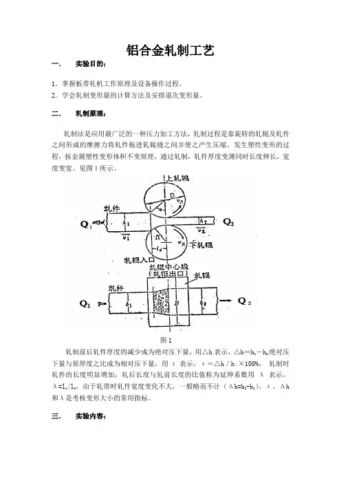
二. 轧制原理:轧制法是应用最广泛的一种压力加工方法,轧制过程是靠旋转的轧辊及轧件之间形成的摩擦力将轧件拖进轧辊缝之间并使之产生压缩,发生塑性变形的过程,按金属塑性变形体积不变原理,通过轧制,轧件厚度变薄同时长度伸长,宽度变宽。
见图1所示。
图1轧制前后轧件厚度的减少成为绝对压下量,用△h 表示,△h =h 1-h 2绝对压下量与原厚度之比成为相对压下量,用ε表示,ε=△h /h 1×100%, 轧制时轧件的长度明显增加,轧后长度与轧前长度的比值称为延伸系数用λ表示,λ=l 1/l 2。
由于轧带时轧件宽度变化不大,一般略而不计(Δb=b 2-b 1)。
ε、Δh和λ是考核变形大小的常用指标。
三. 实验内容:使用两辊板带轧机轧制AlCu合金试件,试件铸态毛坯尺寸:120×15.00×7(mm)。
经多道次轧制使熔铸台毛坯形成轧制态工件,轧制厚度由7mm轧至2mm,将其中一半轧件送到马弗炉时效处理,为下一实验做准备。
四.实验步骤:1.根据轧机传动系统图和轧制原理图结合轧机了解板带轧机的组成,熟悉其结构和轧制机理。
2.润滑各运动部件,启动电源空车运转。
3.按总变形量分配道次压下量,并调整压下装置。
4.喂料轧制,按道次测量并记录相关数据。
5.轧制加工完成关闭电源,快速退回压下装置。
6.清理轧机和工作地点。
7.拟写实验报告。
五.实验装置:图2 轧机基本结构六.实验数据及处理:七. 思考题:1.试述齿轮座(分动箱)的作用?齿轮箱位于辊与减速箱中间起连接传动作用,同时用它控制上下轧辊转速保 持一致2.分析压下量与咬入角之间关系。
]/)(1arccos[21D h h --=α为轧辊直径为咬入角、即为压下量、其中D )( 21αh h -根据实验原理的图示可知.。

铝合金铸轧工艺
铝合金铸轧工艺是指在铝合金材料制备过程中,先将铝合金熔化后,通过浇铸、轧制等工艺进行成型和加工的过程。
铝合金铸轧工艺一般包括以下步骤:
1. 材料准备:选择合适的铝合金材料,根据产品的要求进行材料准备,包括铝合金材料的成分控制和预处理等。
2. 熔炼:将铝合金材料加热至熔点,使其熔化成液态铝合金。
熔炼可采用电炉、气炉等不同方式进行。
3. 浇铸:将熔化的铝合金液浇入预先准备好的铸型中。
铸型可以是砂型、金属型等不同材料制成,根据产品要求进行选择。
4. 冷却和固化:铝合金液在铸型中冷却后逐渐固化成为实体。
固化过程通常需要一定的时间和恒温条件。
5. 压铸:将固化的铸坯放入压铸机中,通过对铸坯进行压力加工,使其具有所需的形状和尺寸。
压铸可以是冷压铸、热压铸等不同方式。
6. 热处理:对压铸后的铝合金进行热处理,包括时效、淬火等工艺,以改善其性能和组织结构。
7. 轧制:经过热处理后的铝合金坯料可以通过轧机进行轧制,使其具有所需的厚度和形状。
8. 退火处理:通过对轧制后的铝合金进行退火处理,消除残余应力,改善其机械性能。
9. 表面处理:对轧制后的铝合金进行酸洗、氧化等表面处理,以提高其表面质量和耐腐蚀性能。
10. 检验和包装:对成品进行检验,包括外观检查、尺寸测量、性能测试等,然后进行包装和贮存。
铝合金铸轧工艺可以根据具体产品的要求进行调整和改进,在不同的铝合金材料、铸型和轧制设备等条件下,工艺参数和工艺流程也会有所差异。
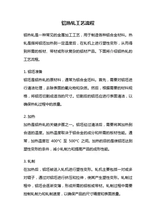
铝热轧工艺流程铝热轧是一种常见的金属加工工艺,用于制造各种铝合金材料。
热轧是指将铝坯加热到一定温度后,在轧机上进行塑性变形,从而得到所需的板材、带材或形状复杂的铝材产品。
下面将介绍铝热轧的工艺流程。
1. 铝坯准备铝坯是铝热轧的原材料,通常为铝合金坯料。
首先,需要对铝坯进行清洁处理,去除表面的氧化物和杂质。
然后,根据需要的材料规格,将铝坯切割成适当的尺寸。
切割后的铝坯应进行表面清洁,以确保热轧过程中的质量。
2. 加热加热是铝热轧的关键步骤之一。
铝坯经过清洁后,需要将其加热到合适的温度。
加热温度取决于铝合金的成分和所需的板材性能。
通常,加热温度在400°C至500°C之间。
加热的目的是使铝坯达到塑性变形的条件,减小轧制力和提高产品的成形性能。
3. 轧制在加热后,铝坯被送入轧机进行塑性变形。
轧机主要包括一对或多对辊子,通过对铝坯进行挤压和拉伸,使其产生塑性变形。
轧制过程中,铝坯会逐渐变薄,形成所需的铝板或带材。
轧制过程中需要控制轧制力和轧制速度,以确保产品的尺寸精度和表面质量。
4. 冷却轧制后的铝板或带材需要进行冷却处理。
冷却可以通过自然冷却或水淬来实现。
冷却的目的是使铝材快速降温,固化其内部晶体结构,提高产品的机械性能和物理性能。
冷却后的铝材需要进行拉伸矫直,消除轧制过程中产生的应力和变形,使其达到平整度和尺寸精度的要求。
5. 表面处理冷却后的铝板或带材需要进行表面处理,以提高其表面质量和耐腐蚀性。
常见的表面处理方法包括酸洗、氧化和涂层等。
酸洗可以去除铝材表面的氧化物和杂质,提高其表面光洁度。
氧化可以形成一层氧化膜,增强铝材的耐腐蚀性。
涂层可以在铝材表面形成一层保护层,提高其耐磨性和耐腐蚀性。
6. 产品检验轧制和表面处理后的铝板或带材需要进行产品检验,以确保其质量符合要求。
常见的检验项目包括尺寸精度、表面质量、力学性能和化学成分等。
产品检验可以通过各种检测设备和方法进行,如尺寸测量仪、表面检测仪、拉伸试验机和光谱分析仪等。
铝合金轧制工艺嘿,咱今儿就来唠唠铝合金轧制工艺这档子事儿!你说铝合金这玩意儿,那可真是了不起啊!就好像是我们生活中的一位超级英雄,无处不在又神通广大。
从汽车到飞机,从建筑到日常用品,哪儿都有它的身影。
那铝合金是咋来的呢?这就得说到轧制工艺啦!想象一下,铝合金就像是一块面团,而轧制工艺呢,就是那双神奇的大手,把这块面团揉啊揉、擀啊擀,最后变成我们需要的各种形状和厚度。
这可不是随随便便就能搞定的事儿哦!就好像你做面条,得掌握好力度和技巧,不然那面条可就粗细不均啦!在轧制过程中,温度可是个关键因素呢!要是温度不合适,那铝合金可能就不乐意啦,要么硬得像块石头,要么软得像摊烂泥。
这就好比你做饭时火候没掌握好,不是烧焦了就是没熟。
所以啊,得把温度控制得恰到好处,就像哄孩子一样,得顺着它的脾气来。
还有啊,轧制的速度也很重要呢!太快了不行,太慢了也不行。
太快了就像你跑步时冲刺过猛,容易摔倒;太慢了呢,又好像蜗牛在爬,效率太低啦。
所以得找到那个最合适的速度,让铝合金乖乖地听话,变成我们想要的样子。
而且哦,轧制设备就像是个大力士,得足够强壮有力才能把铝合金制服。
要是设备不给力,那可就糟糕啦,就像一个虚弱的人想搬动大石头,根本不可能嘛!所以啊,得保证这些设备像钢铁侠一样厉害,才能搞定那些厉害的铝合金。
你说这铝合金轧制工艺是不是很神奇?它就像是一场魔术表演,把普通的铝合金变成了各种神奇的宝贝。
咱生活中的好多好东西可都离不开它呢!它让我们的生活变得更加丰富多彩,更加便捷舒适。
所以啊,咱可不能小瞧了这铝合金轧制工艺。
它虽然看起来不起眼,但实际上却是幕后的大功臣呢!它就像是一位默默奉献的工匠,用自己的双手打造出了无数的美好。
咱得好好感谢它,感谢它为我们的生活带来的这些改变和惊喜。
咋样,现在你是不是对铝合金轧制工艺有了更深的认识和了解啦?哈哈!原创不易,请尊重原创,谢谢!。

铝铸轧机工作原理
铝铸轧机是一种用于加工铝合金材料的设备,通过对铝合金材料进行连续轧制,使其在尺寸和表面质量上得到改善和满足特定的要求。
在铝铸轧机的工作过程中,首先将铝合金坯料放置在轧机的进料端口。
通过传输装置,坯料被送入轧机的工作区域。
在工作区域内,由辊子组成的轧辊对铝合金坯料进行连续的轧制。
轧辊分为上辊和下辊,它们之间的间隙可以调整以适应不同材料的厚度和要求。
当铝合金坯料通过轧辊时,上下辊之间的间隙会逐渐减小,从而使铝合金坯料逐渐变薄,达到所需的尺寸。
除了轧辊之外,铝铸轧机还配备了一系列辅助设备,如张力装置、辊缓冲系统和卷收装置。
这些设备在铝合金坯料被轧制的过程中发挥着重要的作用。
张力装置用于控制铝合金坯料在轧机中的张力,确保坯料在轧制过程中保持稳定。
辊缓冲系统通过调整辊子的压力,避免了可能出现的拉伸和压缩应力,以确保轧制出的铝合金材料表面平整且无缺陷。
最后,轧制完成的铝合金材料会由卷收装置卷起,形成卷材。
卷材可以进一步加工或直接用于制造各种铝合金产品。
总的来说,铝铸轧机通过连续轧制的方式对铝合金坯料进行加
工,通过调整轧辊间的间隙和辅助设备的作用,实现对铝合金材料尺寸和表面质量的改善,以满足特定的要求。
铝合金冷轧及薄板生产技术一、熔炼与铸锭1.1铝合金熔炼铝合金熔炼是生产过程中的重要环节,主要通过将铝合金材料加热至熔点后进行熔炼、精炼、除气、除渣等操作,以获得高质量的熔体。
1.2铸锭铸锭是将熔炼后的铝合金熔体倒入模具中,冷却凝固后形成一定形状和尺寸的铝合金锭。
铸锭的质量对后续的加工和制品质量有重要影响。
二、热轧与冷轧2.1热轧热轧是一种将铝合金铸锭加热至一定温度后进行轧制的工艺,主要目的是通过施加压力使铝合金材料产生塑性变形,获得一定形状和尺寸的板材或带材。
2.2冷轧冷轧是在室温下对铝合金材料进行轧制的过程,主要通过机械外力使铝合金材料产生塑性变形,获得更薄的板材或带材。
三、薄板成型3.1拉伸成型拉伸成型是一种将铝合金板材或带材通过模具进行拉伸变形的过程,主要应用于生产各种形状的铝合金制品。
3.2弯曲成型弯曲成型是一种将铝合金板材或带材通过模具进行弯曲变形的过程,主要应用于生产各种弯曲形状的铝合金制品。
四、表面处理4.1抛光抛光是通过机械或化学方法对铝合金表面进行加工,以获得光滑、亮泽的表面效果。
常用的抛光方法包括机械抛光、化学抛光和电化学抛光等。
4.2喷涂与电镀喷涂和电镀是在铝合金表面涂覆或镀覆其他金属或非金属材料,以提高铝合金制品的耐腐蚀性、美观度和功能性。
常用的喷涂和电镀材料包括油漆、塑胶、金属等。
五、质量检测5.1外观检测外观检测是对铝合金制品的表面质量进行检测的过程,主要通过目视、触觉等方法对制品的外观缺陷进行检查。
5.2尺寸检测尺寸检测是对铝合金制品的尺寸精度进行检测的过程,主要通过测量工具对制品的尺寸进行精确测量。
5.3力学性能检测力学性能检测是对铝合金制品的力学性能进行检测的过程,主要包括硬度、抗拉强度、屈服强度、延伸率等指标的检测。
六、环保与安全6.1有害物质控制铝合金冷轧及薄板生产过程中会产生一些有害物质,如废气、废水、废渣等,需要进行有效的控制和处理,以减少对环境和人体的危害。
铝热轧工艺技术铝热轧工艺技术是指将铝坯料加热到一定温度后进行轧制的工艺过程。
下面将介绍铝热轧工艺技术的基本过程和主要应用。
铝热轧工艺技术的基本过程如下:首先,选择合适的铝坯料,对其进行加热处理,通常采用高温加热炉,使铝坯料达到适宜的轧制温度。
其次,将加热后的铝坯料送入轧机中进行轧制。
铝的热轧温度通常在400-500摄氏度之间,这样可以保证铝材在轧制过程中达到良好的塑性和可塑性,以便轧制出所需的形状和尺寸。
最后,冷却和修整加工,使铝材成品具有所需的机械性能和表面质量。
铝热轧工艺技术的主要应用是在铝板、铝带等铝材的生产中。
铝是一种轻便、耐腐蚀、导电、导热的金属材料,被广泛用于航空航天、汽车、电子、建筑等行业。
而热轧工艺可以使铝材更好地满足各个行业的需求。
例如,在航空航天领域,铝热轧工艺可以轧制出高强度、低密度的铝合金材料,用于制造飞机及其零部件;在汽车领域,铝热轧工艺可以制造轻量化材料,提高燃油经济性和环境友好性;在电子领域,铝热轧工艺可以制造细小尺寸的铝箔,用于电容器和电池等产品;在建筑领域,铝热轧工艺可以制造表面光滑、耐腐蚀的铝板,用于建筑外墙和屋顶等。
铝热轧工艺技术的优势主要体现在以下几个方面:首先,铝热轧工艺可以使铝材达到所需的形状和尺寸,满足各个行业的不同需求;其次,铝热轧工艺可以提高铝材的机械性能,使其具有更好的强度和硬度;再次,铝热轧工艺可以优化铝材的表面质量,减少缺陷和氧化层,提高产品的质量和使用寿命;最后,铝热轧工艺可以增加铝材的加工工艺性能,使其更容易进行后续加工和成形。
总结来说,铝热轧工艺技术是一种重要的铝材加工工艺,可以使铝材具有良好的塑性、可塑性和机械性能,满足各个行业的需求。
在未来,铝热轧工艺技术将进一步发展和创新,提高铝材的质量和性能,推动铝材在各个行业的广泛应用。
7075铝板的轧制工艺
7075铝板的轧制工艺主要包括以下步骤:
1.将7075铝板放于滚花机中进行定位导直操作,选择滚花刀的数量和安全的
位置,并对滚画面位置进行调整,确保滚花刀刚刚好压在滚花面上,把控
好滚花的深度。
2.在进行7075铝板轧制与冷却时,需着重关注以下内容:在机器作业前全面
检查滑动的位置,锁紧手柄,确认好位置,保证各轴承拥有良好的润滑状
态,更换不一样的滚花面需关注调整。
此外,7075铝板的轧制工艺还包括铸轧、热轧等步骤,其中铸轧是利用铝熔体在轧制过程中的粘弹塑性变形行为,获得具有特定组织结构和性能的薄板材料的技术。
热轧是使铸态的7075铝合金坯料在再结晶温度以上进行轧制,获得具有所需尺寸精度和组织性能的薄板材料的技术。
综上所述,7075铝板的轧制工艺是一个复杂的过程,需要经过多道工序和多次加热处理才能获得高质量的薄板材料。
铝合金扁锭轧制工艺流程英文回答:Aluminum Alloy Flat Ingot Rolling Process.The aluminum alloy flat ingot rolling process involves several key steps to transform aluminum alloy ingots into flat, rolled products. The process typically consists of the following stages:1. Ingot Preparation:The aluminum alloy ingots are first heated in a furnace to soften them and make them more workable.The heated ingots are then homogenized to ensure uniform composition and structure throughout the ingot.2. Hot Rolling:The homogenized ingots are passed through a series of hot rolling mills to reduce their thickness and increase their length.Hot rolling is typically performed at temperatures above the recrystallization temperature of the aluminum alloy.The hot-rolled slabs are then annealed to soften them and remove any internal stresses.3. Cold Rolling:The annealed slabs are further rolled in cold rolling mills to achieve the desired thickness, width, and surface finish.Cold rolling is performed at temperatures below the recrystallization temperature of the aluminum alloy.The cold-rolled coils are then subjected to heat treatment processes, such as annealing or tempering, toenhance their mechanical properties.4. Final Processing:The cold-rolled coils may undergo additional processes, such as leveling, slitting, and edge trimming, to prepare them for specific applications.Inspection and testing are performed throughout the process to ensure the quality of the final product.中文回答:铝合金扁锭轧制工艺流程。
铝板的铸轧工艺
铝板的铸轧工艺是指将铝合金熔化后,通过铸造和轧制工艺制成不同尺寸和形状的铝板,以满足不同领域的使用需求。
铝板的铸造工艺包括连铸和直铸两种,其中连铸工艺是通过将熔化的铝合金倒入连续铸造机中进行连续铸造,制成厚度较薄的板材;而直铸工艺则是通过将熔化的铝合金倒入铸模中进行单次铸造,制成厚度较厚的板材。
铝板的轧制工艺包括热轧和冷轧两种,其中热轧工艺是将连铸或直铸的铝板在高温下进行轧制,以减小板材厚度并提高其力学性能;而冷轧工艺则是将热轧后的铝板在常温下进行轧制,以提高其表面质量和精度。
此外,还可以采用涂层、拉伸等工艺对铝板进行进一步加工,以满足特定的使用需求。
总的来说,铝板的铸轧工艺是一个复杂的过程,需要精密的设备和技术,并需要根据不同的需求和使用环境选择适合的工艺和材料。
铝板的应用范围广泛,包括航空航天、汽车制造、建筑装饰、电子产品等多个领域。
- 1 -。
铝加工热轧和冷轧工艺流程
铝加工热轧和冷轧的工艺流程如下:
热轧工艺流程:
1.材料剪切:按照所需尺寸剪切铝合金材料,为后续加工做准备。
2.预处理:
●清洗:去除剪切好的铝合金材料表面的污垢和氧化物。
●酸洗:将清洗后的材料浸泡在酸液中,以除去材料表面的氧化铝层。
●涂油:酸洗处理后,对铝板或铝卷进行涂油处理,防止表面氧化。
3.加热:
●加热炉:将预处理好的铝板或铝卷送入加热炉中,使材料达到适合轧制的温度。
●温度控制:确保材料在轧制过程中保持适宜的温度。
4.热轧:
●轧机设备:包括粗轧机、精轧机和细轧机,将加热后的铝板或铝卷送入轧机中进行轧制。
●轧制辊道调整:通过调整轧机辊道的间距和轧制力度,控制铝板或铝卷的厚度和表面质量。
●过程冷却:轧制过程中对铝板或铝卷进行冷却处理,保证产品性能和形状。
而冷轧工艺流程相对热轧要简单一些,通常包括:
1.开卷:将热轧后的铝卷开卷,送入冷轧机进行加工。
2.冷轧:通过冷轧机对铝材进行进一步加工,达到所需的厚度和精
度。
3.卷取:将冷轧后的铝材卷取成卷,方便后续的运输和储存。
请注意,具体的工艺流程可能因材料种类产品要求以及生产设备的不同而有所差异。
在生产过程中,还需要根据具体情况进行工艺参数的调整和优化,以确保产品质量和生产效率。
制表:审核:批准:。
铝加工热轧和冷轧工艺流程温馨提示:该文档是小主精心编写而成的,如果您对该文档有需求,可以对它进行下载,希望它能够帮助您解决您的实际问题。
文档下载后可以对它进行修改,根据您的实际需要进行调整即可。
另外,本小店还为大家提供各种类型的实用资料,比如工作总结、文案摘抄、教育随笔、日记赏析、经典美文、话题作文等等。
如果您想了解更多不同的资料格式和写法,敬请关注后续更新。
Tips: This document is carefully written by the small master, if you have the requirements for the document, you can download it, I hope it can help you solve your practical problems. After downloading the document, it can be modified and adjustedaccording to your actual needs.In addition, the store also provides you with a variety of types of practical information, such as work summary, copy excerpts, education essays, diary appreciation, classic articles, topic composition and so on. If you want to know more about the different data formats and writing methods, please pay attentionto the following updates.铝合金是一种常见的金属材料,具有轻质、耐腐蚀、导电性好等优点,因此被广泛应用于航空航天、交通运输、建筑等领域。
大型2219铝合金环均匀化轧制工艺铝合金是一种重要的结构材料,广泛应用于航空航天、汽车制造、建筑和其他领域。
其中,2219铝合金由于其优异的机械性能和耐腐蚀性能,在航空航天领域得到了广泛应用。
然而,大型2219铝合金环的生产过程中存在着一些难点,其中包括轧制过程中的均匀化问题。
为了解决这一问题,研究人员提出了一种新的工艺来实现大型2219铝合金环的均匀化轧制。
本文将介绍这一工艺的具体内容,并对其进行分析和讨论。
一、大型2219铝合金环均匀化轧制工艺的背景1.1 2219铝合金的应用领域2219铝合金是一种含铜高的变形铝合金,具有优异的力学性能和耐腐蚀性能,特别适用于要求高强度和耐腐蚀的航空航天结构件。
其在航空航天领域得到了广泛的应用,包括飞机机身、发动机零部件等方面。
1.2 大型2219铝合金环的生产需求随着航空航天工业的发展,对于大型2219铝合金环的需求日益增加。
然而,由于其特殊的合金成分和较大的尺寸,传统的生产工艺难以满足其均匀化的要求,造成了生产效率低下和产品质量不稳定的问题。
二、大型2219铝合金环均匀化轧制工艺的工艺流程2.1 热处理工艺a. 固溶处理将大型2219铝合金环进行固溶处理,使合金内的溶解相达到均匀化分布,为后续的轧制工艺做好准备。
2.2 轧制工艺a. 热轧工艺采用逐级轧制的方法,将经过固溶处理的大型2219铝合金环进行热轧,保证其尺寸的精确和表面质量。
2.3 冷处理工艺a. 冷轧均匀化通过对热轧后的大型2219铝合金环进行冷轧均匀化处理,使其内部的晶粒得到细化,提高其力学性能和表面质量。
三、大型2219铝合金环均匀化轧制工艺的工艺优势3.1 提高产品质量采用新工艺后,大型2219铝合金环的均匀化得到了显著改善,产品的内部结构更加致密,表面质量更加平整,从而提高了产品的机械性能和耐腐蚀性能。
3.2 提高生产效率采用新工艺后,大型2219铝合金环的生产周期得到了缩短,生产效率得到了显著提高,为航空航天工业的发展提供了可靠的材料保证。
铝合金连续铸轧和连铸连轧技术
铝合金连续铸轧和连铸连轧技术
铝合金连续铸轧和连铸连轧技术是一种新兴的材料加工技术,它结合
了铸造和轧制的技术,可以实现铝合金材料的连续加工。
连续铸轧工艺,是把铝合金浇液料加热熔融,然后将熔体倒入熔体模,经过一段时间冷却固化后即可得到铸件,并经过轧制加工,从而提高
了铝合金的力学性能和外观质量。
连铸连轧技术,则是将熔体倒入铸轧机中,一次完成浇注和轧制,实
现熔体的连续加工,从而提高了产量和效率,并可以直接改变铸件的
尺寸和形状,并可以提高质量,降低生产成本。
连续铸轧和连铸连轧技术,不仅可以改善铝合金的力学性能,提高外
观质量,而且可以提高产量,降低成本,一定程度上满足大批量生产
的要求。
它已经被广泛应用于车辆制造、航空航天、电力行业等众多
领域,受到了社会的广泛认可。
总之,铝合金连续铸轧和连铸连轧技术是一种新兴的材料加工技术,
它的应用范围广泛,可以改善铝合金的力学性能,提高外观质量,提
高产量,降低成本,有助于提高生产能力和效率,更好地满足社会对
高品质铝合金产品的需求。
On-Line Sensor for Aluminum Making Process Investigations1Richard F. Conti, 2Kazuharu Hanazaki1Heraeus Electro-Nite Co., LLC, Langhorne PA USA2Heraeus Electro-Nite Japan, Ltd., Ichikawa, JapanKeywords: inclusions, electric-sensing zone, aluminumAbstractIncremental improvements to already efficient and clean aluminum production processes can be guided by metallurgical on-line sensors that provide in-situ measurements of key process variables. A few such sensors are examined in detail correlating aspects of their measuring accuracy under actual plant conditions measuring non metallic particles in molten aluminum.IntroductionA measuring sensor develops from observations that exposure to a specific stimulus results in a response to that stimulus in a distinctive manner. Bundling this distinctive response for the purpose of measuring a physical quantity by converting the response into a signal which can be read and interpreted by an observer is a measuring system. During a manufacturing process for the, measuring systems that provide information describing the status of the process or are readily available are termed, “on-line” due to the immediacy of their response. One segment of on-line sensors that have become common in the manufacturing process of converting raw materials into finished shapes are sensors designed to be immersed into the liquid metal. In many instances, the primary responsive principle of these sensors and their early development exists in a context removed from the target application. Immersion Particle analyzers, LiMCA, (ABB), and ESZ-PAS, (Heraeus Electro-Nite), provide non metallic particle detection in liquid metals based on the electric sensing zone (ESZ), or Coulter Counter principle first utilized in aqueous solutions [1].Inclusion DetectionMolten aluminum is frequently contaminated to some extent by non-metallic inclusions that give rise to defects in the final products. Prior to the development of the initial prototype LiMCA system for molten aluminum measurement at McGill University [3], it was not possible to measure inclusions, in-situ, enabling metallurgical process decisions at key moments during product manufacturing. Typically, in order to determine the quality of cast aluminum shapes regarding inclusions as close to the production process as possible, operators using optical equipment determined the number and sizes of inclusions in a small surface section. Other techniques utilizing sedimentation, filtration and metallographic combinations of scanning electron microscopes and optical scans of polished surfaces to report observed surface irregularities require considerable amounts of time and labor. Compared with these techniques, the electric sensing zone method has the advantage of providing quantitative information on the volume concentration of inclusions, and also on their size distribution from a considerable larger sample size virtually on-demand.Electric-Sensing Zone MeasurementThe electric sensing zone method of particle size analysis involves an electronically conductive liquid induced to flowfrom one vessel to another through a non-conducting orifice bythe alternating use of vacuum and pressure. The vessels are electrically insulated and a constant current, regulated by a ballast resistor, is applied across this orifice by two electrodes, Aand B, connected to a battery.Figure 1. Passage of a non-conducting particle, d, through aninsulating orifice of diameter D gives rise to avoltage pulseΔV.The presence of a non-conducting particle in the fluid flowing through this orifice causes a change in the electrical resistance detected at the aperture as a voltage pulse as shown schematically in Figure 1. The change in resistance of the fluidis proportional to the volume of fluid displaced by the passing particle given by [4]∆(1)where ρe is the electrical resistivity of the liquid, d is the particle diameter, and D is the orifice diameter at its minimum point.When d is not small compared to D, distortion of the currentflow field leads to an increase in effective resistance ∆R AB ,which should then be modified by a correction factor, f (d/D)[5,6].∆f(d/D)(2)1 2 3 4 51 2 3 4 5⁄ 1 0.8 ⁄ (3)Voltage pulses generated in the presence of the applied constant current can then be measured, and the number and size of the particles counted:∆∗ 1 .08 ⁄(4)The passage of a particle through an ESZ of a molten metal measuring system where 25 10 Ω with an applied current of 20 to 60 amperes is very different from those electrolyte fluids of an aqueous Coulter Counter. These high currents result in strong radial electromotive forces accelerating non-conducting particles toward the sidewall of the ESZ [7]. Particles failing to transit the orifice impinge upon the orifice wall leading to unsteady fluid flow, a partially clogged orifice resulting in incorrectly measured ∆V, high system electronic noise, a low particle pass through fraction and early measurement termination from a clogged orifice. The motion of spherical particles in a current carrying liquid metal flowing through a circular pipe are characterized by trajectories dependent upon hydrodynamic and electric fields, particle size, particle density and the property of the fluid [8]. Large particles reach the sidewall faster than smaller particles and dense particles travel further along the orifice before hitting the sidewall as compared to less dense particles. The percentage of particles in the fluid that successfully pass through the orifice and counted is called the “pass through fraction.”The problem of orifice blockage has been extensively studied and numerous solutions proposed to avoid clogging the orifice by large particles. In order to detect small particles, the orifice should be reduced to the lowest possible and the current increased to the highest possible elevate the transient voltage above the background noise of the measuring instrumentation. Both of these strategies increase the likelihood of large particles clogging the measuring orifice. In much of the prior art, the distribution of numerous smaller inclusions rather than the occurrence of few large inclusions justified the elimination, filtering and separation of large inclusions to allow the measurement to proceed consisting of particle diameters typically as low as 10 percent of the orifice diameter. However, when desiring knowledge of the relatively sparse larger particles present in the liquid metal, this requires much larger sample volumes and a new sampling strategy promoting detection, not elimination.Experimental SystemThe ESZ sensor, similar to that developed by Heraeus Electro-Nite for use in molten steel [9], as shown in figure 2 is a metal sampling chamber comprised of a 12 mm ID, 470 mm long quartz tube. A 1200 micron cylindrical orifice with softened contours at the metal inlet surface is laser drilled into the tube sidewall. The unusually larger orifice passage is selected to satisfy the maximum detection for a particle size approaching 800 microns. The chamber tube is coated on all surfaces with a nearly transparent boron nitride coating. The internal electrode, is a steel coupled to a copper bushing and steel chill block which are crimped to a hollow contact pin. The internal pin assembly is used in conjunction with an argon gas supply to purge the chamber and an applied vacuum to draw metal into the chamber.A low resistance electrical contact is maintained between the inner electrode and an air cooled receptacle via a high temperature copper alloy spring. The outer electrodes, designed for immersions up to an hour, not shown in the follow figure, are a pair of titanium alloy rods attached to a steel tube surrounding the upper portion of the chamber makes electrical contact with another air cooled electrical contacting member in the receiving receptacle. For shorter duration immersions of the same sensor design, steel outer electrodes have been employed. All electrodes at their point of contact at the receptical were kept below 150°C by the air cooling system. The sensor is a single use device with no reuseable portions.Figure 2. Inner electrode arrangement and quartz chamber. The outer electrode is not shown.The contact receptacle is part of a measuring lance holder, containing a signal conditioning amplifier connecting to the remote instrumentation by use of a 10 meter detachable shielded cable that houses power, signal, and gas conduits. Power to the ESZ measuring circuit is a 12 volt high ampere capacity battery that is continuously charged during all sampling cycles except during the actual measuring time when all AC power is isolated from the measuring circuit. A custom LabVIEW program operates the electrical and pneumatic systems while ESZ voltage, current and system pressure data are acquired at 32 kHz and analyzed in separate custom software that displays the acquired data waveforms, measures the actual current, identifies the inclusion peaks, evaluates the quality of the data in regard to the electronic noise and reports the size and size distribution of the combined measurement segments. Although the resistivity of the molten aluminums varies according to the specific alloy measured, and this value will change the calculated particle equivalent sphere, the resistivity of pure aluminum is used for the calculation of size.SamplingA Heraeus Electro-Nite Electric Sensing Zone Particle Analysis System, (ESZ-PAS) was installed at a casting factory of Toyota to measure the non-metallic particles in A356 /A319 metal in the holding furnace.To begin the automatic ESZ sampling process argon is flushed through the purge/vacuum lines prior to immersion. The immersion depth was set by a lance holder so that the orifice was between 150-200mm below the bath surface. Approximately 40g of metal is drawn into the sampling chamber with a vacuum pressure of -40 kPa to achieve a flow rate of 4m/s. Since the metal flow is not instantaneous at its target flow, the measuring current is switched on only after the metal pressure set-point is reached. In this fashion, data used in forparticle analysis is acquired only during the middle 2.5 secondsor, ~25g of aluminum. Although more liquid aluminum has passed the orifice before and after the analysis period, it has been found that the quality of that data is low for low fluid velocity. After data acquisition, the sampling vacuum is relieved and the obtained metal and senor components equilibrate during a 30 second rest period after which this metal is purged from the chamber by argon. The liquid around the orifice entrance is stirred by a 30 second argon flush at 7 kPa from the open orifice. The alternate, high current cycle begins immediately following this purge time.Metal coupons were taken during some ESZ sampling for comparison.(3a)(3b)Figure 3. Instrumentation screens for sampling procedure, (3a) and sampling analysis, (3b).Figure 4. Fractured surface of a metallurgical coupon. SEM analysis of acquired coupons during an earlier measurement determined predominately Al2O3 and Al-Si particles.Transient pulse detection by the ESZ-PAS software is a complex combination of peak characteristics translated into a set of logic statements. In order to be identified as a peak, a set of data points collected at 32000/s, must pass predetermined criteria. The baseline data points are filtered then scanned point by point looking for a set number of consecutive data points each achieving a minimum voltage rise over the back averaged baseline that could potentially signal the start of a voltage peak. Once identified other criteria such as, but not limited to, the rate of rise of the leading edge, time of peak half height, total peak duration and undershoot at the foot of the failing edge must all meet their acceptance criteria. After qualification, the height is measured over the local baseline average and ∆V is obtained for use in equation 4. Particle counts of the low current cycle and the high current cycle are detected by the ESZ-PAS peak detection algorithm. An equivalent sphere diameter is calculated from the transient voltage peak height, grouped according to a particle size index.DiscussionThe dual current ESZ-PAS was operated in Toyota at various times for different conditions duplicating scenarios that would occur under actual plant conditions. The number of low and high current measurement cycles and the time between each cycle are part of the parameter setting of the instrumentation. Typically, the number of cycles is selected depending upon the rate of erosion of electrodes which is a function surface refreshing rate and total contact time with the aluminum. For sampling 1kg of liquid metal, 40 cycles of 1m11sec each will take nearly 50 minutes. Both electrodes, the boron nitride coating of the quartz and the stability of the orifice dimension were adequate for the duration of the measurement.Numerous evaluations at different were reviewed to establish that the distribution pattern of sized groups developed quickly with approximately 10 cycles of measurement, figures 5 and 6.Figure 5. Assembly of accumulated inclusion distribution patterns after 2, 10, 20, and 40 cycles of low and high, (18-47A), current measuring segments from the holding tank. Figure 6. Assembly of accumulated inclusion distribution patterns after 2, 4, 6, 8, 10 and 18 cycles of low and high, (21-58A) current measuring segments support observation that for these experimental conditions, the distribution reaches a steadystate after~250g of material.Since the accumulated particle count is a combination of two applied measuring currents there could be an excess of detected particles where the low detection limit of the high current cycle overlaps the upper limit of the low current cycle. In practice, the ratio of high to low current levels can coincide with the pass through fraction so that the low detection limit of the low current segment approximates a built in division as in figure 7. When this is not possible, selection criteria for mutual cut-off levels can be easily applied.Figure 7. Accumulation of particles detected by the same sensor, D=1200, in the same metal, grouped by applied current.Even with the most noise free environment possible, there is a minimum peak height above the baseline which could reasonably be considered a “peak,” in other words, the minimum reported inclusion. There can arise a circumstance where a “debate” occurs as to the amount of small particles counted and the amount of baseline noise improperly identified as particles. In the ESZ-PAS system a cut-off of counted peaks, is preset by the pre-calculated particle the size of 15% of the orifice at the measurement current. On the contrary, for large particles because the peak voltage is so much greater than the baseline voltage, the ease at which large particles can be identified leads to no debate.The high currents employed by traditional ESZ systems to detect small particles will promote a low success rate for the detection of large particles due to the influence of the electromagnetic “pinch effect” on the particle trajectory passing, and in most cases, failing to pass through the measuring orifice. The conspicuous absence of large particles detected at 68A under identical conditions alternated in time with a low current sensor detecting large particle clearly support the earlier modeling work of Mei and Guthrie [8] that low pass through fractions are current created operating conditions even in the situation of a large orifice. Additionally, the lack of positive baseline jumps, most likely the consequence of particle attachment or fluid detachment from the orifice walls becomes apparent as current is reduced. Although it is suggested that a large orifice will lead to coincidence counting, [10] the chance that two particles enter the orifce at the same time, this is observed in water testing where high concentrations of particles are purposefully added, but in actual industrial melts only to a limited extent.When the measuring current is set at the low current setting the previously identifiable small particles vanish into the baseline but the larger particles stand clearly above the baseline, not deflected away from the ESZ entrance allowing for a high pass through fraction. A high current can now be applied to measure small particles which have a high pass-through fraction.The presence of a low pass-through fraction for large particlesresults in a skewed ESZ distribution and due to their lowoccurrence rate on a metal sample surface, support this under reporting. An accurate assessment of large particles, when this is the intended measurement, would necessarily mandate a measuring conditionConclusionsThe on-line sensors described here are immersion type sensors for use in molten aluminum and molten salt. Success in this specific market depends upon adaptations to the measuring apparatus through understanding of the unique requirement of the measured media. Particle size and size distribution measuring system for in molten aluminum where a high electromagnetic fields in the electric sensing zone results in “pinch” effects lowering the ability to detect large particles has been modified to provide dual measuring currents for the same size orifice providing alternate detection cycles of large and small particles.AcknowledgementThe authors wish to thank; Toyota Motor Corporation for providing assistance and support for ESZ measurements in an industrial environment.References1.R.I.L Guthrie and D. Doutre: Proc. Int. Seminar onRefining and Alloying of Liquid Aluminum and Ferro-Alloys, Trondheim, Norway, 1986, pp. 146-163.2.H. Takada, T. Shibata, K. Nihei, T. Inoue, ImmersionThermometer for Molten Metal, Japanese PatentJP62019727, 19873. D. Doutre, R.I.L. Guthrie, “A Method and Apparatus forthe Detection and Measurement of Particulates in LiquidMetals”, U.S. Patent 4,555,662, November 26, 1985.4.R.W. Deblois, and C.P. Bean: Rev. ScientificInstruments, 1970, vol. 41 (7), pp 909-915.5.R.W. Deblois and C.P. Bean and R.K.A. Wesley: J.Colloid Interface Sci., 1977, vol. 61 (2), pp. 323-3356.W.R. Smythe: Phys. Fluids, 1961, vol. 4 (6), pp 756-7597.Mei Li and R.I.L Guthrie: “On the Detection andSeparation of Inclusions in Liquid Metal CleanlinessAnalyser (LiMCA) Systems”, Metallurgical and MaterialsTransactions B, Vol. 32B, Aug. 2000, pp 767-777.8.Mei Li and R.I.L Guthrie: “In-situ Detection of Inclusionsin Liquid Metals: Part I. Mathematical Modelling of theBehaviour of Particles Traversing the Electric SensingZone”, Metallurgical and Materials Transactions B, Vol.32B, Dec. 2001, pp 1067-1081.9.R.P. Stone, C.C.Liu. P.C. Glaws: “Experience With anInnovative On-Line Inclusion Determination System forLiquid Steel”, AIST Conf. Proc.Vol 1, AISTech 200810.M. Isac, A. Chakraborty, L. Calzado, R.I.L. Guthrie:“Development of an Aqueous Particle Sensor (APSIII),System as a Research Tool for Studing the Behaviour ofInclusions in Water Models of TUndish Operations”,Sensor, Sampling and Simulation for Process Control.TMS Conf. Proc. 2011。