制造工程与技术(热加工)英文版14 Forging of Metals
- 格式:pdf
- 大小:2.15 MB
- 文档页数:80
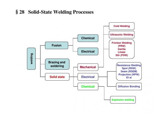
Chapter 13 Rolling of Metals(金属的轧制)•13.1Introduction•13.2Flat Rolling•13.3Flat Rolling Practice•13.4 Rolling Mills•13.5Shape-Rolling Operations•13.6 Production of Seamless Pipe and Tubing•13.7 Continuous Casting and Rolling Integrated Mills and Minimills13.1 Introduction•Rolling(轧制)–the process of reducing the thickness (orchanging the cross-section(横截面)) ofa long workpiece by compressive forcesapplied through a set of rolls(轧辊).Øaccounts for about 90% of all produced by metalworking processesØfirst development in the late 1500sØsimilar to the rolling of dough(面团)with a rolling pin(擀面杖/擀面棍)Rolls (轧辊)Classification of Rolling •By productØflat rolling(平板轧制)Øshape rolling(型材轧制)Øtube rolling(轧管)•By temperatureØhot rolling (热轧)Øcold rolling(冷轧)Flatrollingreduce the thicknessShaperollingchange the cross-sectionFigure 13.1 Schematic outline of various flat-and shape-rolling processes. Source:American Iron and Steel Institute.13.2 Flat RollingA strip(带料/条料)of thickness h o enters the roll gap(辊缝/辊隙/辊间距离)and is reduced to thickness h f by a pair of rotating rolls, each roll being powered through its own shaft by electric motors(电动机).thickness >6 mm Øplate: Øsheet:厚板thickness ≤ 6 mmProduction of Flat Rolling薄板•strip (条料/带料)•strip in coil (卷料/卷材)•machine structures•ship hulls (船体)•boilers (锅炉)•bridges•nuclear vessels (核反应容器)•battleships and tanks : 300mm (12in.) thick : 150mm (6 in.) thick : 100~125mm thick•automobile bodies•aircraft fuselages (机身)•appliances (用具/器具)•kitchen and office equipment •food and beverages container •aluminum foil (铝箔): 1.8 ~1.9 mm thick : 0.1 mm thick : 0.008 mm (8μm) thickFlat Rolling Process辊间距离/轧辊开度•the thickness is reduced: △h = h o–h f •the length is increased: △l = l f–l o •the width is increased: △w = w f –w o 压下量延伸量宽展量V o:the velocity of the strip at the entrance(入口)V f:the velocity of the strip at the exit(出口)V r:the surface speed of the rolls ,which is constant(不变的)V0 < V fV0 < V r< V fThere is relative sliding(相对滑动)between the rolland the strip along the arc ofcontact in the roll gap, L.Definition: One point along the contact length, whereV s :the velocity of the strip,which is variable during thecourse of rollingV r :the surface speed of the rolls,which is constant while rollingNeutral Point or No-Slip Point(中性点/无滑移点)V s = V r13.2.1 Frictional Forces(摩擦力)•Since there is relative sliding between the roll and the strip along the arc of contact in the roll gap, the frictional forces, which oppose motion, act on the strip.Fig13.2 (b) Friction forces acting on strip surfacesØThe rolls pull the material into the roll gap through a net frictional force (净摩擦力)on the material.Øis necessary for rolling materials.Significance (重要性/意义)of Friction what ’s thedirection of net frictional force?“咬入”Disadvantage of FrictionØEnergy is dissipated(浪费)in overcoming friction; thus, increasing friction means increasing forces and power(功率)requirements.Øcould damage(损害)the surface of the rolled product.A compromise(折衷/妥协)has to be made, onewhich includes low coefficients of friction(摩擦系数)by using effective lubrication(润滑).Max Draft(最大压下量)•reduction in thickness, △hh0-h f = µ2RμRdraftμ: the coefficient of the frictionR: the roll radius13.2.2 Roll Force and Power RequirementRoll Force (轧制力)Power (功率)per roll 18L : the roll-strip length of contact arc w : the width of the stripY avg : the average true stress (平均真实应力)T: torqueω : angle speed轧制力矩/扭矩n: revolutions (转数)per second of the roll N: rpm (revolutions perminute) of the rollavg F LwY = (/2)(2) /60 W /60000 W /33000 P T F L n FLN FLN k FLN hp ωππππ==⋅===W: watt (瓦特)k W :kilowatthp :horsepower (马力)Four-high Rolling-mill (四辊轧机)Figure 13.3 Schematic illustration of a four-high rolling-mill stand (轧机机座), showing its various features. The stiffnesses (刚度)of the housing, the rolls, and the roll bearings are all important in controlling and maintaining the thickness of the rolled strip.机架轴承座/底座支撑辊支撑辊工作辊螺杆或液压机构Too high roll force cancause the rolls:Ødeflection (挠度/弯曲)Øflattening (压扁)a.reducing friction, μ;ing smaller diameter rolls, R , to reduce the contact area;c.taking smaller reductions per pass, Δh , to reduce the contact area;d.rolling at elevated temperature , to lower the strength(强度)to the material.L ≈2h Rµ∆=20 a v gF L w Y =Reducing Roll Forces• e. applying longitudinal tensions(纵向拉力)to the strip during rolling.–As a result, the compressive stresses required to deform thematerial plastically become smaller–particularly important in rolling high-strength metal–Tensions can be applied at the entry zone (back tension) (后拉力/后张力), by applying a braking action(制动)to thereel which supplies the sheet to the roll gap (the pay-off reel)(开卷机), by some suitable means.–Tensions can also be applied at the exit zone (front tension)(前拉力/前张力), by increasing the rotational speed of thetake-up reel(卷取机).–Steckel rolling(斯特克尔轧制法): be carried out by fronttension only, with no power supplied to the rolls开卷机/松卷机13.2.3 Geometric Considerationsa.Roll bending (轧辊弯曲)b.Thermal camber of rolls(轧辊热挠度)c.Flattening of rolls(轧辊压扁)d.Spreading of strip(条料展宽)Methods:1)the higher elastic modulus (弹性模量)of the roll material, the smaller the roll deflection (轧辊挠度)2)roll camber (轧辊凸度): grinding the rolls so that their diameter at the center is slightly larger than at their edges.3)application of moments (力矩/Roll Bending (轧辊弯曲)Figure 13.4 (a) Bending of straight cylindrical rolls, caused by the roll force. (b) Bending of rolls ground with camber (凸度), producing a Crown (隆起)Results:the rolled strip tends to be thicker at its center than at its edges. Reasons:roll forces tend to bend the rolls elastically (弹性地)•Application of moments(弯矩)at their bearings–通过加在辊体两端的反力矩来平衡轧辊两端工作压力产生的弯矩,减小轧辊的变形Thermal Camber (热挠度)Results:can produce strips that are thinner at the center than at the edges.Methods:the total (or final) camber can be controlled by varying the location of the coolant (冷却液/冷却剂)on the rolls during hot rolling.Reasons:the rolls becomes slightly barrel-shaped (鼓形/桶形)because of the heat generated by plastic deformation (塑性变形)during rolling.rollstripFlattening of Rolls (轧辊压扁)Results:It produces a larger roll radius and a larger contact area for the same draft. The roll force in turn, increases with increased flattening.Methods:enhancing the strength of roll materials or the radius of the rollReasons:elastic deformation caused by roll forcesSpreading of a Strip (条料展宽)Figure 13.5 Increase in the width (spreading) of a strip in flat rolling (see also Fig. 13.2a). Similarly, spreading can be observed when Phenomenon:–For strip with high w 0/h 0ratios , the width of the material remains effectively constant after rolling.–For strip with smaller w 0/h 0ratios , the width increases considerably in the roll gap.Spreading :–increase in widthMethods:use of vertical rolls in contact with the edges of the rolled product (edging rolling ) (立轧/轧边)Influence Factors of SpreadingSpreadingfrictionR/h 0ratiow 0/h 0ratio(width constraint )(longitudinal constraint )13.3 FLAT-ROLLING PRACTICE1.Hot Rolling (热轧/初轧)—done above the recrystallization temperature(再结晶温度)Figure 13.6 Changes in the grain structure of cast or of large-grain wrought metals during hot rolling.cast structure wrought structuredendritic(树枝状的)coarse(粗大的)nonuniform grains(不均匀的晶粒)brittle(脆/脆性的)porous(多孔的)equal/uniform grain(等轴晶) finer (细化的)enhanced ductility(韧性好的) non-porosity(无孔)wrought structure(锻造组织)cast structure (铸造组织)Advantages of Hot Rolling•reduce grain size•improve strength and ductility(塑性/延展性/柔韧性)–breaking up(破裂/打碎)brittle grain boundaries (晶界)–closing up(压合/压实)internal defects(内部缺陷), especially porosity (多孔性)Temperature of Hot RollingThe temperature for hot rolling varies with different metals.•aluminum (Al) alloys(铝合金): about 450℃(850℉) •alloy steels(合金钢): 1250℃(2300℉) •refractory alloys(高温合金/难熔合金):1650 ℃(3000℉)•slab •bloom •billet Products of the First Hot-rolling OperationØrectangular in cross-section (矩形截面)Ørolled into plates and sheets laterØhas a square (正方形)cross-sectionØat least 150mm on the sideØprocessed further, by shaping rolling, intostructure shapes, such as I-beams (工字梁)and railroad railsØsquare Øwith a cross-section area smaller than blooms Ørolled into various shapes, such as round rods (圆棒)and bars (杆材), by the use of shaped rolls扁坯小方坯大方坯连续铸件或铸锭圆管坯wire rod 盘条无缝钢管焊接钢管制管钢板酸洗和润滑结构型材钢轨HotrollingDefect(缺陷)in Hot Rolling•Scale(氧化皮/氧化垢):consisting mainly of the oxides(氧化物)Conditioning(清理/处理)Methods •using a torch(气炬)( scarfing 火焰表面清理)•pickling with acids (acid etching,酸洗/酸蚀)•by such mechanical means as blasting with water(喷水)•grinding(研磨)•better surface finish (表面光洁度)•better dimensional tolerances (尺寸公差)•enhanced mechanical properties (机械性能)Advantages of Cold Rolling2.Cold Rolling (冷轧)—carried out at room temperature (室温)because of lack of scale due to strain hardening(应变硬化)without thermal expansion3.Pack Rolling (迭板轧制)—two or more layers of metal are rolled together, which improves productivity(生产率).Example: Aluminum Foils•pack rolled in two layers•foil-to-foil side: matte(无光泽的)•foil-to-roll side: shiny(光亮的)and bright •reason: contact with the polished(抛光的)rolls ?satiny(光滑的)finish4. Temper Rolling or Skin Pass(硬化冷轧或表面光轧)-the steel metal is subjected to a final light rolling pass(工步)of 0.5% to 1.5% reduction-produce compressive residual stress(残余压应力)onthe surfaceReason:•For mild steel(低碳钢/软钢), when stretched during sheet-forming operations, undergoes yield-point elongation(屈服点延伸), a phenomenon that causes surface irregularities(不整齐)called stretcher strains(拉伸应变纹)or Lueder’s bands(吕德38斯带)( Section 16.3).5. Levelling Rolls(矫直轧)—to improve flatness(平面度/平整度), the rolled strip is passed through a series of leveling rolls(矫直辊)Figure 13.7 A method of roller levelling to flatten Method:rolled sheets.•Several different roller arrangements are used.•Each roll is usually driven separately, by an individual electric motor.•The strip is flexed(弯曲)in opposite directions as it passes through the sets of rolls.Levelling Rolls•在辊式矫直中,金属板经过不断地交错变形弯曲。
![[新版]热加工(英文版)](https://img.taocdn.com/s1/m/a7bded15df80d4d8d15abe23482fb4daa48d1d55.png)
Molding Powder metallurgy Machining Casting Castability Ceramics UniformityGeometric Ambient temp Alloy ApplicationFinishing Net-shape manufacturing Mechanical property Gating systemSprue Runner Gate Riser Oxide Velocity--viscosityDie Inclusion Wall Subscript Impermeable Incompressible Friction Loss Mass Insoluble particl Index Spiral Shrinkthe gating system (sprue, runners and gates)√10.1 Why is casting an important manufacturing pro cess?√10.9 describe the features of a gating system.√10.16 what is a riser?√10.47 A sprue is 10 in. long and has a diameter of 5 in. at the top, where the metal is poured. If a designed flow rate of 40 in3/sec is to be achieved, what should be the diameter of the bottom of the sprue?expendable-pattern casting一次性模样铸造(lost foam)blank毛坯bead珠、粒pentane戊烷aluminum铝slurry泥浆long production run = large production run polyalkylene聚烯PMMA聚甲基丙烯酸甲酯,(有机玻璃/亚克力Acrylics)poly methyl meth acrylaterefractory难熔的, hot-work die steel, slush = slurry泥浆, large (long) ~ small production runs, sodium钠silicate硅酸盐water glass水玻璃, fin鱼翅,鳍lawnmower割草机,gear齿轮integral完整的prior先copper铜,警察bronze青铜(Cu+锡Sn) brass 黄铜(Cu+锌Zn),horizontal or vertical卧式or立式, plunger活塞, pot, ejector box顶杆框,stationary platen定模板, ladle长柄勺stationary固定的sleeve袖子tendency倾向rate=rank/grade,clamping force合模力, stroke冲程identical相同的~different不同的checking裂缝lubricant润滑剂,flash飞边, knurled滚花bushing轴衬liner衬套,groove = spline开键槽, shaft 轴, popsicle冰棒snow cones雪糕optical 光学的,视力的specimen范例,标本,样品,样本,待试验物ductility延展性mechanical property机械性能extreme 极端flaw瑕疵,裂缝detector探测器sniffer嗅探器investigate研究surfacedestructive and nondestructive test有损与无损探伤pressure tightness, scent气味carry out=do, storage and retrieval systems存取系统pattern &mold making,CAD/CAM: computer aided design and manufacture melt, pour conveyor生产线automation, industrial robot, jobbing a.做零活的safety: fume浓烟crucible坩锅flux熔化hygroscopic吸湿的pyrometer高温计calibration刻度apron围裙,挡板11.1 describe the differences between expendable and permanent molds.11.5 what is the function of a core? What are core prints?11.14 what are parting agents?12.1 list the general design considerations in casting12.3 what is shrinkage allowance? Machining allowance?12.8 name the important factors involved in the economic of casting operationsStapler wrench foil film toaster electrical-resistance hull ball bearing elevator Ingot slab wrought pellet flake ore synthetic work piece stock translucent Beverage insulator spark plug reinforce discrete disk=disc bolt bulk tube polyamide聚酰胺PC= polycarbonate聚碳酸酯酯ester脂fat, grease, rougePE= polyethene聚乙烯PVC= polyvinyl chloride 聚氯乙烯PTFE =Poly tetra fluoro ethylene聚四氟乙烯PP= polypropene聚丙烯PS= polystyrene 聚苯乙烯ABS [汽] anti-skid brake system. 防滑刹车系统[化] Acrylonitrile Butadiene Styrene丙烯腈-丁二烯-苯乙烯PU= polyurethane聚氨酯PMMA=Polymethymethacrylate 聚甲基丙烯酸甲酯Polygram宝丽金(唱片公司)。

专业英语阅读(一)教案张新房Part II: Metal-Casting Processes and Equipment金属铸造工艺与设备In this part, some important and fundamental knowledge about casting must be understood. For this chapter, we should know the differences of Chinese meanings for these professional English words, and I will address these important parts.Forming: 成型Molding: 造型Powder metallurgy:粉末冶金Pouring:浇注Ornament:装饰物Intricate: 复杂的Hollow: 中空的Fig. II. 1 Cast parts in a typical automobile 图2.1一个典型的汽车中的铸造部件Water pump: 水泵Pulley: 滑轮Grill: 栅栏Intake and exhaust manifold: 进气和排气管Disk brake: 刹车片Brake drum: 制动鼓Brake cylinder: 闸缸Lettering:编字码Differential housing: 差速机壳Transmission housing: 变速机壳Engine block: 汽缸体Carburetor: 化油器Piston: 阳模Alternator housing: 同步发电机壳Fig. II. 2. Outline of metal-casting processes described in part II.图II.2. 在第二章中所描述的金属铸造工艺概要Chapter 10 Fundamentals of Metal-Casting金属铸造基础For this chapter, it was divided into these parts:1.Introduction: 简介2.Solidification of metals: 金属的凝固3.Fluid flow: 流体流动4.Fluidity of molten metal: 熔融金属的流动性5.Heat transfer: 热传递6.Defects: 缺陷First, 1. IntroductionThe casting process basically involves three steps:a.pouring molten metal into a mold patterned after the part to be manufactured; (把熔融金属浇注到加工好的模具型腔)b.allowing it to cool and solidify (冷却和凝固)c.removing the metal from the mold (从模具中取出金属)As we know, the casting is the oldest process to manufacture part of tool in the human being’s history, because it has many advantages compared with other manufacturedprocesses as follows:✓ complex shapes, such as differential housing (差速机壳) used in the automobile,crankshaft (曲轴) and so on;✓ Very large part, such as engine housing used in the ship making.✓ Utilize the work pieces that other manufactured processes can not produce ofuneconomic, such as turbine blade (涡轮机叶片).So, it is essential for us to understand the fundamentals of metal casting by studying this book hard.There are some important considerations in the casting operation as follows:✧ The flow of the molten metal into the mold cavity: 熔融金属流入模具型腔,Fluidity.✧ The cooling and solidification of metal in the mold: 金属在模具中的冷却和凝固: heat transfer: 热传导.✧ The influence of different type of mold materials, different heat transferringability, 不同的模具材料具有不同的热传导能力.In this part, we talked about some introductions of metal casting; in the next, we will talk the second part: solidification of metals.2. Solidification of metalsAs we know, for different metals, such as pure metals and alloys, the solidification processes are different, so they will be divided into pure metal and alloy to be discussed different solidification processes.1, Pure metalsFor pure metal, the melting point is constant, so, the solidification is like this one:熔化潜热 After reaching melting point solidification from interface and then to center with different grain type and sizeRelease of latentheat of fusionChill zone: 极冷区,白口区,grain size due to very high cooling rate.Columnar zone: 柱状区,large grain size due to lower cooling rate and heterogeneous nucleation.Equiaxed zone: 等轴晶区,homogeneous nucleation.Fig. 10.2. Development of a preferred texture (择优质构) at a cool mold wall. Note that only favorably oriented grains grow away from the surface of the mold.We can see, different metals have different solidified structures, and the nucleationagents affect it.Fig. 10.1 Schematic illustrationof three caster structure ofmetals solidified in a squaremold; a, pure metals; b,solid-solution alloys; c,structured obtained by usingnucleating agents(孕育剂).Fig. 10.3. Schematic illustration ofalloy solidification and temperaturedistribution in the solidifyingmetal. Note the formation ofdendrites in the mushy zone (多空隙的区域).10.2.2 alloysThe solidification process of alloys can be schematically illustrated from Fig. 10.3. From this figure, we can see, the solidification takes place in a temperature range, Tl and Ts. The solidification process of this type alloy can be illustrated as follow:arms and branches.The structure of dendrite influences the properties of casting seriously, so it is essential to find and study the effectors on its structure.As mentioned above, the structure of dendrite is affected by the mushy zone; in other word, it can be described as different mushy zone during solidification, and the mushy zone can be named as freezing range, as this:Fig. 10.4 (a) Solidification patterns for gray cast iron in a 180mm square casting. Note that after 11min. of cooling, dendrites reach each other, but the casting is still mushy throughout. (b) Solidification of carbon steel in sand and chill (metal) molds. Note the difference in solidification patterns as the carbon content increasesFreezing range = Tl-Ts, the temperature difference between Tl and Ts during solidification.For example: for pure metals and eutectic alloys, freezing range = 0, so, no mushy zone, no dendrite formation.Usually, the short freezing range < 50o C, for example, Fe-base alloys.The long range freezing rang > 110o C, example, Al and Mg-base alloys, and these alloys are in a mushy state throughout most of solidification process.Effect of cooling rateThe casting structure is affected seriously by the cooling rate:Usually, for slow cooling rate (<102K/s), coarse dendrite formation;Faster cooling rate (on the order of 104K/s), finer dendrite formation;Higher cooling rate (106~108K/s), amorphous formation.As cooling rate increases, the grain size decreases, so strength and ductility enhanced, that is hall-petch formula.For the solidified structure, it can be certified by the ratio of G/R, where G is thermal gradient at the interface of liquid and solid, and R is the rate at which the liquid-solid interface moves. Typical values for G range from 102 to 103K/m and for R from 10-3 to 10-4m/s. Dendritic type structures ( Figs. 5.5a and b) typically have an ratio in the range of 105 to 107, whereas ratios of 1010 to 1012 produce a plane-front, nondendritic liquid-solid interface (Fig. 10.6).Fig. 10.5. Schematic illustration of three basic types of cast structures: (a) columnar dendritic; (b) equaiaxed dendritic; and (c) equiaxed nondendritic.Fig. 10.6. Schematic of caststructures in (a) plane front,single phase, and (b) plane front,two phases.10.2.3. structure-property relationshipAll castings are hoped to meet design and service requirements. Usually, the property is up to structure. The compositions of dendrites and the liquid metal are given by the phase diagrams of particular alloys, usually binary alloys. As cooling rate very low, dendrite with uniform composition develops. Normal (fast) cooling rate, core dendrites develop with different composition at surface and center, known as concentration gradient (浓度梯度): higher content of alloying element in the surface layer than that of center. That is due to solute rejection during solidified process, resulting in microsegregation (微观偏析).Macrosegregation (宏观偏析) involves differences in composition throughout the casting.Normal segregation (正常偏析), verse segeration (反向偏析), the reason is that liquid metal ( having a higher concentration of alloying elements) enters the cavities developed from solidification shrinkage (收缩) in the dendritic arms which solidified sooner.Gravity segregation (重力偏析) describes the process whereby higher-density inclusions (夹杂) or compositions sink (下沉) and lighter elements (such as antimony in antimony-lead alloy (锑-铅)) float (上浮) to surface.Inoculants (孕育剂) induce the nucleation of the grains throughout the liquid induced heterogeneous nucleation.Convection promotes the formation of an outer chill zone, refines grain size and accelerates the transition from columnar to equiaxed grains.Dendrite multiplication: 枝晶增殖, rheocasting: 流变铸造In this part, we talked about the solidification process for different metals and the property-structure relation; next, the fluid flow will be talked.10.3. Fluid flowThe fluid flow is most important factor in casting. As shown in fig. 10.7, the casting process is described as: the molten metal is poured through a pouring basin (转包,浇注槽) or cup. It then flows through the gating system (浇注系统) (sprue, runners and gates, 注流口, 流道, 内浇道) into the mold cavity. Sprue is a vertical channel through which molten metal flows downward in the mold. Runners are the channels that carry the molten metal from the sprue to the mold cavity, or connect the sprue to the gate. The gate is that portion of the runner through which the molten metal enters the mold cavity. Risers (冒口) serve as reservoirs (储液槽) to supply the molten metal necessary to prevent shrinkage during solidification, as shown in Fig. 10.7.Trap contaminant: 捕获杂质, premature cooling: 过早冷却, gas entrapment: 夹气 Gating system design is the most important part to get high quality castings.Two basic principles of fluid flow are relevant to gating design: Bernoulli`s theorem and law of mass continuity.Bernoulli`s theorem: 百努利定律t cons gv g p h tan 22=++ρ 10.2 Where:h: the elevation above a certain plane, p: pressure at that elevation, v: velocity of the liquid at at elevation, ρ: the density of the fluid, g: gravitational constant.Conservation of energy requires that, at a particular location, in this system, the relationship is satisfied:f g v g p h g v g p h +++=++2222222111ρρ 10.3 Fig. 10.7. Schematic illustrationof a typical riser-gated casting.Risers serve as reservoirs,supplying molten metal to thecasting as it shrinks duringsolidification.Where, subscripts (下标) 1 and 2 represent two different elevations, and f represents the frictional loss in the liquid as it travels downward through the system.Continuity (连续性)The law of mass continuity (质量连续性) states that for incompressible (不可压缩的) liquid and in a system with impermeable (不可渗透的) wall, the rate of flow is constant:2211v A v A Q == 10.4WhereQ: the rate of flow, A: the cross-sectional area of the liquid, and v: the average velocity of the liquid in that cross-sectional location. The description 1 and 2 refer to two different locations in the system. For example, for sprue design: 2121h h A A = 10.5 so, the area of the bottom in the sprue is smaller than that of top, that means tapered sprue (圆锥型铸道).Aspiration: 吸出, choke: 节流口,缩颈Recall that in a free-falling liquid ( such as water from a faucet: 水龙头) the cross-section area of the stream decreases as it gains velocity downward. If we design a sprue with a constant cross-section area and pour the molten metal into it, regions may develop where the liquid loss contact with the sprue walls. As a result aspiration, a process whereby air is sucked in or entrapped in the liquid, may take place. On the other hand, tapered sprues are now replaced in many systems by straight-sided sprures with a choke to allow the metal to flow smoothly.回想自由落下的水流 (例如从水龙头流下的水), 其横截面积随其获得的向下的速度而减小。
英文原文:A.1 FORGINGBulk defirnnation of metals refers to various processes, such as forging, rolling, or extruding, where there is a controlled plastic flow or working of metals into useful shapes. The most well known of these processes is forging where deformation is accomplished by means of pressure, impact blows, or a combination of both.Hammer ForgingHanuner forging consists of striking the hot metal with a large semiautomatic hammer. If no dies are involved, the forging will be dependent mainly on the skill of the operator. If closed or impression dies are used, one blow is struck for each of several (lie cavities. A- gain, productivity and quality depend to a large degree on the skill of the hanimer operator and the tooling.Press ForgingPress forging is characterized by a slow squeezing action. Again, open or closed dies may be used. The open dies are used chiefly for large, simple-geometry parts that are later machined to shape. Closed-die forging relies less on operator skill awl more on the design of the preform and forging dies.2 As an example of the versatility of the process, newer developments have made it possible to produce bevel gears with straight or helical teeth. Rotation of the die (luring penetration will press bevel gears with spiral teeth.Open-die ForgingOpen-die forging is distinguished by the fact that the metal is never completely confined as it is shaped by various dies. Most open-die forgings are produced on flat, V, or swaging dies. Round swaging (lies and V dies are used in pairs or with a flat die. The top (lie is attached to the ram of the press, and the bottom die is attached to the hammer anvil or, in the case of press open-die forging, to the press bed.As the workpiece is hammered or pressed, it is repeatedly manipulated between the dies until hot working forces the metal to the final dimensions, as-shown in Fig. 1. After forging, the part is rough- and finished-machined. As an example of the amount of material allowed for machining, a 6.5 in. diameter shaft would have to be forged to 7.4 in. dianieter.In open-die forging of steel, a rule of thumb says that 50 lb of falling weight is required for each square inch of cross section.Impression-die ForgingIn the simplest example of impression-die forging, two dies are brought together, and the workpiece undergoes plastic deformation until its enlarged sides touch the side walls of the die (Fig. 2). A small amount of material is forced outside the die impression, forming flash that is gradually thinned. The flash cools rapidly and presents increased resistance to deformation, effectively becoming a part of the tool, and helps build up l)ressUre inside the bulk of the work- piece that aids material flow into unfilled impressions.Closed-die forgings, a special form of impression-die forging, does not depend on theformation of flash to achieve complete filling of the (lie. Thus closed-die forging is considerably more demanding on die design. Since pressing is often completed in one stroke, careful control of the workpieee volume is necessaiy to achieve complete filling without generating extreme pressures in the dies from overfilling.Extrusion ForgingAs with upsetting, extrusion forging is often accomplished by cold working. Three principal types of metal displacement by plastic flow are involved. Backward and forward, tube, and impact extrusion are shown in Fig. 3. The metal is placed in a container and corn- pressed by a ram movement until pressure inside the metal reaches flow-stress levels. The workpiece completely fills the container, and additional pressure causes it to leave through an orifice and form the extruded product.Extruded products may be either solid or hollow shapes. Tube extrusion is used to produce hollow shapes such as containers and pipes. Reverse-impact extrusion is used for mass production of aluminum cans. The ram hits a slug of metal in the die at high impact, usually 15 times the yield strength of the metal, which causes it to flow instantaneously up the walls of the die. Other common hollow extrusion products are aerosol cans, lipstick cases, flashlight cases, and vacuum bottles. Secondary operations, such as heading, thread rolling, dimpling, and machining, are often needed to complete the items.Generally steel impacts are limited to 2.5 times the punch diameter. Hydraulic presses areused for loads of over 2000 tons because they have a greater variation in stroke length, speed,and other economic advantages. Tolerances vary with materials arid design, hut productionruns calling for 0.002- to 0.005-in, tolerance are regularly made.Roll ForgingRoll forging in its simplest form consists of a heated billet passing between a pair of rollsthat deform it along its length (Fig. 8-4). Compared to conventional rolling processes, therolls are relatively small in diameter and serve as an arbor into which the forging tools aresecured. The active surface of the tool occupies only a portion (usually half) of the rollcircumference to accommodate the full cross section of the stock.The reduction of the cross section obtainable in one pass is limited by the tendency of thematerial to spread and form an undesirable flash that may be forged into the surface as a90rota- defect in the subsequent operations. The workpiece is int roduced repeatedly withtion between passes.Ring RollingRing rolling offers a homogeneous circumferential grain flow, ease of fabrication andmachining, and versatility of material size . Manu- facture of a rolled ring starts with asheared blank, which is forged to a pancake, punched, and pierced.There is no limit to the size of the rolled rings, ranging from roller-bearing sleeves to Fig.4 Roll forging rings 25 ft in diameter with face heights of 80 in. Various profiles may berolled by suitably shaping the driven, idling rolls.CAD/CAM in ForgingCAD/CAM is being increasingly applied to frging. Using the three-dimensional description of a machined part, which may have been computer designed, it is possible to generate the geometry of the associated forging. Thus the forging sections can be obtained from a common (laiR base. Using well-known techniques, forging loads and stresses can be obtained and flash dimensions can be selected for each section where metal flow is approximated as ro dimensional (plane strain or axisymmetric ). In some relatively simple section geomethes, computer simulation can be conducted to evaluate initial guesses on preform sections. Once the preform geometry has been developed to the designer¡¯s satisfaction, this geometric data base can utilized to write NC part programs to obtain the NC tapes or disks for machining.A.2 HEAT TREATMENT OF METALAnnealingThe word anneal has been used before to describe heat-treating processes for softening and regaining ductility in connection with cold working of material. It has a similar meaning when used in connection with the heat treating of allotropic materials. The purpose of full annealing is to decrease hardness, increase ductility, and sometimes improve machinability of high carbon steels that might otherwise be difflcult to cut. The treatment is also used to relieve stresses, refine grain size, and promote uniformity of structure throughout the material.Machinability is not always improved by annealing. The word machinability is used to describe several interrelated factors, including the ability of a material to be cut with a good surface finish. Plain low carbon steels, when fully annealed, are soft and relatively weak, offering little resistance to cutting, but usually having sufficient ductility and toughness that a cut chip tends to puli and tear the surface from which it is removed, leaving a comparatively poor quality surface, which results in a poor machinability rating. For such steels annealing may not be the most suitable treatment. The machinability of many of the higher plain carbon and most of the alloy steels can usually be greatly improved by annealing, as they are often too hard and strong to be easily cut at any but their softest condition .The procedure for annealing hypoeutectoid steel is to heat slowly to approximately 60C︒above the Ac3 line, to soak for a long enough period that the temperature equalizes throughout the material and homogeneous austenite is formed, and then to allow the steel to cool very slowly by cooling it in the furnace or burying it in lime or some other insulating material. The slow cooling is essential to the precipitation of the maximum ferrite and the coarsest pearlite to place the steel in its softest, most ductile, and least strained condition. NormalizingThe purpose of normalizing is somewhat similar to that of annealing with the exceptions that the steel is not reduced to its softest condition and the pearlite is left rather fine instead of coarse. Refinement of grain size, relief of internal stresses, and improvement of structural uniformity together with recovery of some ductility provide high toughness qualities in normalized steel. The process is frequently used for improvement of machinability and for stress nlief to reduce distortion that might occur with partial machining or aging.The procedure for normalizing is to austenitize by slowly heating to approximately80above the Ac3 or Accm3 temperature for hypoeutectoid or hypereuteetoid steels, C︒respectively; providing soaking time for the formation of austenite; and cooling slowly in still air. Note that the steels with more carbon than the eutectoid composition are heated above the Aom instead of the Ac used for annealing. The purpose of normalizing is to attempt to dissolve all the cementite during austenitization to eliminate, as far as possible, the settling of hani, brittle iron carbide in the grain boundaries. The desired decomposition products are smallgrained, fine pearlite with a minimum of free ferrite and free cementite. SpheroidizingMinimum hardness and maximum ductility of steel can he produced by a process called spheroidizing, which causes the iron carbide to form in small spheres or nodules in a ferrite matrix, in order to start with small grains that spheroid ize more readily, the process is usually performed on normalized steel. Several variations of processing am used, but all reqllin the holding of the steel near the A1 temperature (usually slightly below) for a number of hours to allow the iron carbide to form on its more stable and lower energy state of small, rounded glohules.The main need for the process is to improve the machinability quality of high carbonsteel and to pretreat hardened steel to help produce greater structural uniformity after quenching. Because of the lengthy treatment time and therefore rather high cost, spheroidizing is not performed nearly as much as annealing or normalizing.Hardening of SteelMost of the heat treatment hardening processes for steel are basel on the production of high pereentages of martensite. The first step. therefore, is that used for most of the other heat-treating processes-treatment to produce austenite. Hypoeutectoid steels are heated to approximately 60CC above the Ac3 temperature and allowed to soak to obtain temperature unifonnity and austenite homogeneity. Hypereutectoid steels are soaked at about 60CC above the A1 temperature, which leaves some iron carbide present in the material.The second step involves cooling rapidly in an attempt to avoid pearlite transformation by missing the nose of the i-T curve. The cooling rate is determined by the temperature and the ability of the quenching media to carry heat away from the surface of the material being quenched and by the conduction of heat through the material itself. Table1 shows some of the commonly used media and the method of application to remove heat, arranged in order of decreasing cooling ability.High temperature gradients contribute to high stresses that cause distortion and cracklug, so the quench should only as extreme as is necessary to produce the desired structure. Care must be exercised in quenching that heat is removed uniformly to minimize thermal stresses.For example, a long slender bar should be end-quenched, that is, inserted into the quenching medium vertically so that the entire section is subjected to temperature change at one time. if a shape of this kind were to be quenched in a way that caused one side to drop in temperature before the other, change of dimensions would likely cause high stresses producing plastic flow and permanent distortion.Several special types of quench are conducted to minimize quenching stresses and decrease the tendency for distortion and cracking. One of these is called martempering and consists of quenching an austenitized steel in a salt at a temperature above that needed for the start of martensite formation (Ms). The steel being quenched is held in this bath until it is of uniform temperature but is removed before there is time for fonnation of bainite to start. Completion of the cooling in air then causes the same hard martensite that would have formed with quenching from the high temperature, but the high thermal or ¡°quench¡± stresses that are the primary source of cracks and warping will have been eliminated.A similar process performed at a slightly higher temperature is called austempering. In this case the steel is held at the bath temperarnre for a longer period, and the result of the isothermal treatment is the formation of bainite. The bainite structure is not as hard as the martensite that could be formed from the same composition, but in addition to reducing the thermal shock to which the steel would be subjected under normal hardening procedures, ii is unnecessary to perform any further treatment to develop good impact resistance in the high hardness rangeTemperingA third step usually required to condition a hardened steel for service is tempering, or as it is sometimes referred to, drawing. With the exception of austempered steel, which is frequently used in the as-hardened condition, most steels are not serviceable “as quenched”. The drastic cooling to produce martensite causes the steel to be very hard and to contain both macroscopic and microscopic internal stresses with the result that the material has little ductility and extreme brittleness. Reduction of these faults is accomplished by reheating the steel to some point below the A1 (lower transformation) temperature. The stnictural changes caused by tempering of hardened steel are functions of both time and temperature, with temperature being the most important. It should be emphasized that tempering is not ahardening process, but is, instead, the reverse. A tempered steel is one that has been hardened by heat treatment and then stress relieved, softened, and provided with increased ductility by reheating in the tempering or drawing procedure.The magnitude of the structural changes and the change of properties caused by tempering depend upon the temperature to which the steel is reheated. The higher the ternperatun, the greater the effect, so the choice of temperature will generally depend on willingness to sacrifice hardness and strength to gain ductility and toughness. Reheating to below lOOt has little noticeable effect on hardened plain carbon steel. Between lO(YC and 200T, there is evidence of some structural changes. Above 200T marked changes in structure and properties appear. Prolonged heating at just under the A1 temperature will result in a spheroidized structure similar to that produced by the spheroidizing process.In commercial tempering the temperature range of 25O-425 is usually avoided because of an unexplained embrittlement, or loss of ductility, that often occun with steels ternpered in this range. Certain alloy steels also develop a ¡°temper brittleness¡± in the tempera- ture range of 425-600C︒, particularly when cooled slowly from or through this range of temperature. When high temperature tempering is necessary for these steels, they are usually heated to above 600C︒and quenched for rapid cooling. Quenches from this temperature, of course, do not cause hardening because austenitization has not been accomplished.中文译文:B.1 锻造金属变形方法有多种,比如通过锻造、滚压或挤压,使金属的塑性流动或加工受到控制而得到有用的形状。
Chapter 14 Forging of Metals(金属的锻造/锻压)•14.1 Introduction•14.2 Open-Die Forging•14.3 Impression-Die and Closed-Die Forging•14.4 Related Forging Operations•14.5 Rotary Swaging•14.6 Forging-Die Design•14.7 Die Materials and Lubrication•14.8 Forgeability•14.9 Forging Machines•14.10 Forging Practice and Process Capabilities •14.11 Die Manufacturing Methods; Die Failures •14.12 The Economics of Forging14.1 Introduction•Forging(锻造/锻压)–A workpiece is shaped (formed) by compressive forces applied through various dies(模具)and tools(工具).•one of the oldest metal working processes –4000bc •trationally be performed with a hammer(锤)and anvil(砧/平砧)•mostly require a set of dies and such equipment as a press(压力机)or a forging hammer(锤锻机).•Typical forged products:–bolts (螺栓)–rivets (铆钉)–connecting rods (连杆)–gears (齿轮)–shaft (轴)–hand tool (手工具)–structural components (结构组件)discrete partsForging (锻件)(a)Source : Forging Industry Association.预锻件终锻件近净形/近成品形状净形/最终形状锻造齿净形挤出花键净形bevel gear (伞齿轮)ForgingFigure 14.1 (b) Landing-gear(起落架/着陆装置)components for the C5A and C5B transport aircraft, made by forging. Source: Wyman-Gordon Company.typical forged partsFigure 14.1 (c) general view of a 445 MN (50,000 ton) hydraulic press. Source: Wyman-Gordon Company.Hydraulic Press (液压机)Forging Process (锻压/锻造工艺)Forging Process-2锻造在制坯中的应用•一般机器或机械上的金属零件的传统生产过程是:冶炼——制坯——切削加工——热处理。
•制坯是为切削加工零件提供毛坯的。
•制坯的方法通常有三种:铸造、轧制和锻造。
•铸造坯料结构具有很多缺陷,轧制只能生产截面简单的型材。
•因此,机械制造业中,重要的机械零件,如齿轮、轴、汽车万向节、摇臂、前叉、前桥、连杆等,凡是受力恶劣且性能要求高的零件都是用锻造方法加工毛坯的。
Outline of Forging and Related Operations下料加热锻造后加工检测Figure 14.2• A typical forging operation involves the following sequence of steps:preparing forgingblank (casting ingot)heat the workpiece preheat andlubricate thedieslubricatethe blankforgingthe partclean the forging,check its dimensions perform additionaloperationsinspectinghot forgingcoldforging13Grain Flow Comparison •Characteristics of forged part:–metal flow and grain structure can be controlled–have good strength and toughness(强度与刚度);–can be used reliably for highly stressed and critical(关键的)applications.Figure 14.3 A part made by three different processes, showing grain flow. (a) casting, (b)machining, (c) forging. Source: Forging Industry Association.比较•铸造件(Casting)有不可避免的缺陷,如晶粒粗大、结构疏松、具有多孔,其组织和性能均较差。
•切削件(Machining)的内部晶粒大小和结构不改变,且其金属纤维组织被切断了,使得零件强度下降。
•锻造件(Forging)在经受了塑性变形和再结晶,粗大的树枝状结晶组织被破碎,疏松和孔隙被压实、焊合,内部组织和性能都得到了提高。
Characteristics of Forging Processes TABLE 14.1Process Advantages LimitationsOpen die Simple, inexpensive dies; useful for smallquantities; wide range of sizes available;good strength characteristics Limited to simple shapes; difficult to hold close tolerances; machining to final shape necessary; low production rate; relatively poor utilization of material; high degree of skill requiredClosed die Relatively good utilization of material;generally better properties than open-dieforgings; good dimensional accuracy; highproduction rates; good reproducibility High die cost for small quantities; machining often necessaryBlocker type Low die costs; high production rates Machining to final shape necessary; thick websand large fillets necessaryConventional type Requires much less machining than blockertype; high production rates; good utilizationof materialSomewhat higher die cost than blocker typePrecision type Close tolerances; machining oftenunnecessary; very good material utilization;very thin webs and flanges possible Requires high forces, intricate dies, and provision for removing forging from diesClassification of Forginga.depending on temperature–cold forging(冷锻):at room temperature–hot forging(热锻): above recrystallization temperature –warm forging(温锻): between room temperature andrecrystallization temperatureb.depending on tools–Open-Die Forging(自由锻造)–Impression-Die Forging(模锻)–Closed-Die Forging(闭式模锻/闭模锻造)–Preicison Forging (精密锻造)Comparison of Cold Forging to Hot Forging•Cold forging:–requires greater forces–workpiece materials must have sufficient ductility–good dimensional accuracy–good surface finish–enhanced mechanical properties•Hot forging:–requires smaller forces–loose dimensional tolerance–rough surface finish•Forgings(锻件)generally require additional finishing operations(精加工工艺)–heat treating to modify properties–then machining to obtain accurate finished dimensions •These additional operations can be minimized by precision forging(精密锻造)–a net-shape or near-net shape forming processes(净成形或近净成形工艺)–can reduce the number of operations required–reduce the manufacturing cost•Production methods of a Component:–by forging–by casting–by powder metallurgy(粉末冶金)–by machining(机加工/切削加工)•Production process used for a component is decided by:–economical requirement –properties requirement Østrength (强度)Øtoughness (刚度/韧性)Ødimensional accuracy (尺寸精度)Øsurface finish (表面光洁度)Øinternal or external defects (内部或外部缺陷)14.2 Open-Die Forging(开模锻造)•the simplest forging process•also called free forging(自由锻)•sizes can vary from very smallparts to very large partsupper die workpiece lower die•also called flat-die forging (平模锻造)•reduction in height increases the diameter of the forged part •die surfaces may have simple cavities (型腔)1.Uppseting (镦粗)–a solid (实心的)workpiece placed between two flat dies and reduced in height by compressing it.上模下模Barreling in UpsettingFigure 14.4 (a) Solid cylindrical billet upset between two flat dies. (b) Uniform deformation of the billet without friction. (c) Deformation with friction. Note barreling of the billet caused by friction forces at the billet-die interfaces.Reasons & Methods:–caused by frictional forces at the die-workpiece interfaces –can be minimized if an effective lubricant is used–caused by thermal effects (热效应)in hot forging can be minimized by using heated dies鼓形/桶形ideal conditions (理想条件)actual operationpancaking (压扁)nonuniform deformationUpsetting Practice2.Cogging (拔长)–the thickness of a long bar is reduced by successive(连续的)forging steps at specific intervals(间隔/间距).• a basic open-dieforging operation•also called drawing out•small contact area perstroke(行程/冲程)•no requiring largeforces or machineryFigure 14.5 Two views of a cogging operation on a rectangular bar. Blacksmiths use this process to reduce the thickness of bars by hammering the part on an anvil. Note the barreling of the workpiece.Cogging PracticeCogging PartsBlacksmiths(铁匠)perform such operations with a hammer and an anvil using hot pieces of metal.iron fences14.3 IMPRESSION-DIE AND CLOSED-DIE FORGING1.Impression-die Forging(模锻)–the workpiece acquires the shape of the die cavities(impressions)(型腔/模腔)while being forged between two shaped dies .Figure 14.6 Stages in impression-die forging of a solid round billet. Note the formation of flash,which is excess metal that is subsequently trimmed off (see Fig. 14.8).Crankshaft (曲轴/机轴)and Its Diesdie cavities (impressions)Flash (飞边)•excess (多余的)metalflows outward of thecavity•subsequently trimmed off(切边)•Significance (重要性/意义)of the flash–thin flash cools rapidly–has higher frictional resistance (摩擦阻力)–subjects the material in the die cavity to high pressures –encouraging the filling of the die cavity.Law of Minimum Resistance(最小阻力定律)Figure 14.7 (a) Stages in forging a connecting rod for an internal combustion engine. Note the amount of flash required to ensure proper filling of the die cavities. (b) Fullering, and (c) edging operations to distribute the material when preshaping the blank for forging.Steps of Impression-die Forging Processa.preparing blankb.preforming processesc.blockingd.impression die forginge.removing flasha.Preparing Blank(备料/下料)–cutting(切削)or cropping(剪切)from anextruded or drawn bar stock(棒料)–a preform(预成形件)in operations such aspowder metallurgy(粉末冶金)–casting(铸造)–a preform blank in a prior(先前的)forgingoperation形工艺)b.Preforming Processes(预成–used to distribute(分布/分配)the material into various regions of the blank–such as fullering and edging•fullering(压槽)–material is distributedaway from an area •edging(压边)–material is gathered intoa localized area)c.Blocking(预锻/粗锻/初锻/胎膜锻–formed into the rough shape of final part, usingblocker dies(预锻模)–the final operation to give the forging its final shape in impression dies (终锻模)d.Finishing Forging (终锻)–by a trimming(切边)operation.e.Removing Flash(去除飞边)Impression-die ForgingTrimming Flash from a Forged Part凸模/冲头固定凸模/冲头切边凹模金属块(废料)Figure 14.8 Trimming flash from a forged part. Note that thethin material at the center is removed by punching(冲孔).2.Closed-die Forging and Flashless Forging(闭式模锻和无飞边模锻)•flash does not form;•the workpiececompletely fills the diecavity.Figure 14.9 Comparison of closed-die forging to precision or flashless forging of a cylindrical billet. Source: H. Takemasu, V. Vazquez, B. Painter, and T. Altan.1.accurate control of the volume of materialØundersize (尺寸不足)blanks prevent the complete filling of the die cavity;Øoversize (尺寸过大)blanks generate excessive pressures and may cause dies to fail prematurely (过早失效)or to jam (压裂).2.proper die design Two Essential Conditions in Closed-die Forgingdifference among :open-dieimpression-dieclosed-die14.3.1 Precision Forging (精密锻造)•the part formed is at or close to the finaldimensions of the desired component•known as net-shape or near-net-shape forging(净成形/近净成形工艺).Optimization of Forging Process Sequence1. The use of preforming operation only where it is necessary2. No sizing after heat treatment Billet production Preforming + annealing + lubrication FormingPunching Deburring Heat treatment + shot blastingSizing Soft annealingCuttingLubrication (Bonderite)(磷化)Usually forbig gears Forming performed on a mechanical press Annealing,QuenchingTemperingStraight the distortion Production Process Sequence of Bevel Gear去毛刺校正/精压冲孔成形预成形+退火+润滑Billet•Material–SCM440 (DIN 42CrMo4) -chromium molybdenum steel(铬钼钢)d •Production process–Soft annealing:hardness under 80HB–Sawing(锯切)of the bars (or billet shear)–Lubrication (phosphating(磷化处理)+ lubrication with soap) •Dimensions–d= 22 -0.2mm–h= 40 ±0.3 mm–m= 119.4 ±1 gF = total production process forceF c = closing force (force between upperand lower die)F f = forming force (force acting on the punches)F = F c F f F=F c +F f FcF cTool Set (模架)for Bevel Gear Production-provided by hydraulic unit -provided by pressLower punch Lower dievUpper punchUpper dievvvvlay in the billet close the dies form with the diesRequirements of Precision Forging•higher capacity equipment, because of the greater forces required to obtain fine details on the part •special and more complex dies•precision control of the billet’s volume and shape •accurate positioning(定位)of the billets in the die cavityinvestment(投资)Advantages of Precision Forging•parts having greater accuracies, which can significantly reduce the number of subsequent finishing operations •no or less material is wastedmanufacturing cost•Thus, the choice between conventional forging and precision forging requires an economic analysis, particularly in regard to the production volume(产量/生产批量).Application of Precision Forging •Aluminum(Al)and Magnesium(Mg)alloys:–are particularly suitable,because of the relativelylow forging loads and temperatures that they require;•Steel and Titanium (Ti);•Typical precision-forged products:–gears–connecting rods–housings(机架/罩盖)–turbine blades(涡轮叶片)Precision Forged PartsPrecision Forging Dies。