本特利振动速度变送器
- 格式:pdf
- 大小:69.29 KB
- 文档页数:6
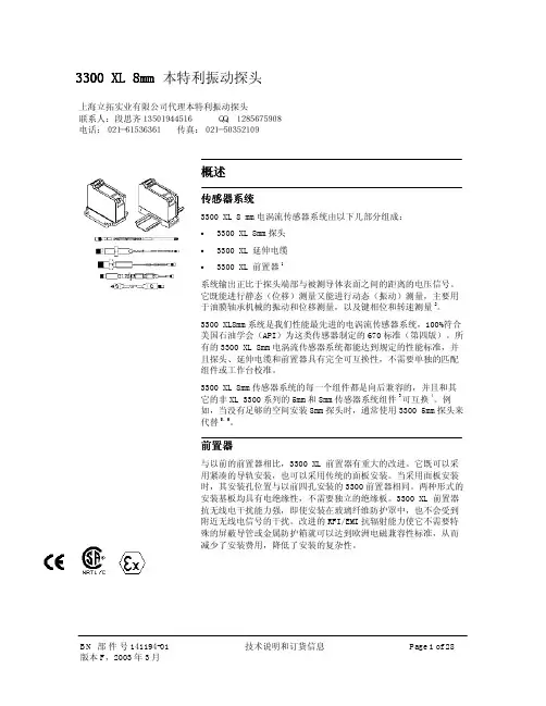
3300 XL 8mm 本特利振动探头概述传感器系统3300 XL 8 mm 电涡流传感器系统由以下几部分组成:• 3300 XL 8mm 探头 • 3300 XL 延伸电缆 •3300 XL 前置器1系统输出正比于探头端部与被测导体表面之间的距离的电压信号。
它既能进行静态(位移)测量又能进行动态(振动)测量,主要用于油膜轴承机械的振动和位移测量,以及键相位和转速测量2。
3300 XL8mm 系统是我们性能最先进的电涡流传感器系统,100%符合美国石油学会(API )为这类传感器制定的670标准(第四版)。
所有的3300 XL 8mm 电涡流传感器系统都能达到规定的性能标准,并且探头、延伸电缆和前置器具有完全可互换性,不需要单独的匹配组件或工作台校准。
3300 XL 8mm 传感器系统的每一个组件都是向后兼容的,并且和其它的非XL 3300系列的5mm 和8mm 传感器系统组件3可互换4。
例如,当没有足够的空间安装8mm 探头时,通常使用3300 5mm 探头来代替5,6。
前置器与以前的前置器相比,3300 XL 前置器有重大的改进。
它既可以采用紧凑的导轨安装,也可以采用传统的面板安装。
当采用面板安装时,其安装孔位置与以前四孔安装的3300前置器相同。
两种形式的安装基板均具有电绝缘性,不需要独立的绝缘板。
3300 XL 前置器抗无线电干扰能力强,即使安装在玻璃纤维防护罩中,也不会受到附近无线电信号的干扰。
改进的RFI/EMI 抗辐射能力使它不需要特殊的屏蔽导管或金属防护箱就可以达到欧洲电磁兼容性标准,从而减少了安装费用,降低了安装的复杂性。
上海立拓实业有限公司代理本特利振动探头联系人:段思齐13501944516 QQ:1285675908电话:021-61536361 传真:021-503521093300 XL的SpringLoc 端子带不需要特殊的安装工具即可紧固。
由于不需要螺丝紧固,不会发生松动,所以连线更坚固。
DescriptionAccessories contribute to a reliable transducer system. Installing proximity probes during outages usually requiresone or more mounting accessories to help simplify the task.3300XL Transducer AccessoriesDatasheetBently Nevada Machinery Condition Monitoring145668Rev.HThese accessories allow you to quickly and efficiently install proximity probes and route the associated cables out of the machine case. These parts also help shield the cables from electrical noise and adverse environmental conditions. Having the proper mounting hardware on-site during the probe installation saves time and money for those responsible for the project.Junction boxesJunction boxes are normally mounted on or near the exterior of a machine case and enclose electrical connections in weatherproof or explosion-proof environments. Sealtite™ flexible conduit Flexible conduit routes probe cables safely to the sensor housing and then back to the monitors. The conduit protects transducer wiring from damage that splashing liquids or accidental contact with other equipment can cause.Sealtite flexible conduit consists of a galvanized steel core with an extruded thermoplastic cover. Pipe fittings are made of steel with a zinc-plated, chromate finish and are compatible with fittings found on our watertight equipment enclosuresProbe mounting bracketsProbe mounting brackets attach internally mounted proximity probes to the machine case. S upplied mounting bolts attach the bracket to the bearing or other location inside the machine casing. The bracket holds the probe and allows for adjustment of the probe tip relative to the observed surface.For most installations, use the standard 137492 non-clamping aluminum probe bracket. When using the 137491 brackets for 3/8-inch diameter smooth case probes, tightening the bolts will compress the probe hole around the probe and lock the probe into its preset gapped position. If your application requires additional electrical isolation from the mounting location (as in some generator and electric motor bearing locations), use the 27474 phenolic probe bracket. These mounting brackets are compatible with our 3300 and 3300 XL proximity probe systems, including 5 mm, 8 mm and NSv™ probes.To ensure that the brackets screws remain fastened within the machine, secure the screws with safety wire. Each mounting bracket includes special screws with holes drilled for safety wire.Cable SealThe optional 10076 Cable Seal is mainly for use in cable routing applications. It restrains the coaxial cable from movement, prevents abrasion, and provides splash protection. One end of the cable seal has a 1/4-18 NPT thread that allows you to thread it into a 4190-36 Adapter.The cable seal has an aluminum body and an oil-resistant, slit grommet so that you can install it over armored or non-armored cable without removing the connectors. AdapterThe optional 4190 Adapter attaches a junction box to the machine case. It also allows mounting of the proximity probe in some instances.The adapter offers a variety of threads and configurations. A dapter threads and configurations that are not listed in this data sheet may be available. P lease contact your sales representative for more information. Explosion-proof fittingsExplosion-proof fittings provide seals for housings in Division 1 and in Zone 0 and 1 hazardous areas. The fittings include sealing compound, packing fiber, and the appropriate adapter. Fitting kits are available. Refer to Explosion-Proof Fittings on page 6 for details and part numbers.Low-pressure cable sealThe 43501 Low-Pressure Cable Seal provides egress for up to 4 75Ω and/or 95Ω 3300XL, 3300 and 7200 cables, or up to 2 25mm DE or 50mmDE transducer cables, through a single hole in a machine case or other barrier.The cable seal is constructed of 303 stainless steel and a molded silicon rubber grommet and prevents leakage of fluids along the outer jacket of the cable. The seal has threads on both ends and fits into a tapped hole on the machine case or barrier. External pipe threads enable the seal to mate to conduit or housings. You can use the low-pressure cable seal only with non-armored cables. Its design seals pressures up to 345 kPa (50 psi) when properly installed.High-Temperature Cable TiesThe 173873 high-temperature cable tie is an economical alternative to metal brackets in high-temperature applications. These cable ties are molded from VICTREX® PEEK™ polymer for multiple uses in extreme environments up to +180°C (+356°F).SpecificationsJunction BoxesCylindrical Junction Box P/N 03818016 ComponentsMain body and blankcoverDimensionsOverall Height76 mm (3.0 in)Body Diameter89 mm (3.5 in)Hub-to-Hub121 mm (4.75 in) Base to Hub Center16 mm (0.64 in) Fittings3/4-14 NPT5 placesMaterial AluminumOptional Extension for 03818016 P/N 03818022ComponentsMain body Dimensions (Extensiononly)Overall Height93mm (3.7 in)Body Diameter90mm (3.6 in)Hub-to-Hub (flats)91 mm (3.6 in)Total ExtendedHeight150 mm (5.90 in) Material Aluminum Rectangular Junction Box P/N 03818065 ComponentsMain body and cover Dimensions Overall Height27.9 mm (1.10 in) Width of Body38.1 mm (1.50 in) Length of Body95.3 mm (3.75 in) Fittings1/2-14 NPT2 places Material Aluminum Rectangular Junction Box P/N 03818066 ComponentsMain body and cover Dimensions Overall Height61.0 mm (2.40 in) Width of Body44.5 mm (1.75 in) Length of Body102 mm (4.00 in) Fittings3/4-14 NPT2 places Material Aluminum Sealtite Flexible Conduit Components Refer to Figure 4.Fitting Options1/2-14 NPT3/4-14 NPTLength As ordered BracketsClamp Mounting Bracket for 3/8-inch diameter smooth body probesDimensions Refer to Figure 5.Mounting Screw Thread Size Options 10-24 UNC-2A M5 x 0.8-6gMaterial AluminumNon-Clamping Mounting Bracket for threaded case probesDimensions Refer to Figure 6. Mounting Screw Thread Size10-24 UNC-2Aor M5 x 0.8-6g Material Aluminum Probe Lock NutThread Sizes 3/8-24 UNF-2B M10 x 1-6HFeatures Lock nut with holes to attachsafety wire.Cable Seal (P/N 10076) Components Refer to Figure 7Overall length (assembled)35mm (1.4 inches) in tightened conditionAdaptersFeatures Refer to Figure 8 4190-01Dimensions Internal Diameter9.53 mm (0.375 in) Internal thread type1/4-18 NPT External thread type1/2-14 NPT Overall Length38.1 mm (1.50 in) 4190-03Internal Diameter11.1 mm (0.437 in) Internal thread type1/4-18 NPT External thread type3/4-14 NPT Overall Length46.0 mm (1.81 in) 4190-04Internal Diameter7.14 mm (0.281 in) Internal thread type1/4-28 UNF-2B External thread type1/2-14 NPT Overall Length38.1 mm (1.50 in) 4190-06Internal Diameter10.3 mm (0.406 in) Internal thread type3/8-24 UNF-2B External thread type1/2-14 NPT Overall Length38.1 mm (1.50 in) 4190-16Internal Diameter10.3 mm (0.406 in) Internal thread type3/8-24 UNF-2B External thread type3/4-14 NPT Overall Length46.0 mm (1.81 in) 4190-20Internal Diameter16.7 mm (0.656 in) Internal thread type5/8-18 UNF-2B External thread type3/4-14 NPT Overall Length46.0 mm (1.81 in)4190-34Internal Diameter7.14 mm (0.281 in) Internal thread type1/4-28 UNF-2B External thread type3/4-14 NPT Overall Length56.1 mm (2.21 in) 4190-36Internal Diameter10.3 mm (0.406 in) Internal thread type1/4-18 NPT3/8-24 UNF-2B External thread type3/4-14 NPT Overall Length56.1 mm (2.21 in) Material304 Stainless Steel Explosion-Proof Fittings29368-01 Optional Fitting KitKit contains the following:03818056Hazardous area ¾” sealing fitting,conduit04576120 4 OZ adhesive sealant20892-02fiber seal03839246.750” aluminum plug72340 Fitting KitKit contains the following:03839246.750” aluminum plug 038500213/4 to 1/2 reducer thread fitting 49871-01cable grip assembly 03839153grommet sealing 250-312 ring 03839154grommet sealing 312-375 ring 20892-02fiber seal038180563/4 conduit fitting 03839155ring cable fitting 045761278 OZ adhesive sealant 04576120 4 OZ adhesive sealant 04760000string tag labelFeaturesRefer to Figure 9.Dimensions03818055Conduit size1/2-14 NPT Overall Length69.9 mm (2.75 in) Width49.3 mm (1.94 in) Min. turn radius63.5 mm (2.50 in) 03818056Conduit size3/4-14 NPT Overall Length69.9 mm (2.75 in) Width49.3 mm (1.94 in) Min. turn radius63.5 mm (2.50 in) 03818058Conduit size1-1/4 NPT Overall Length102 mm (4.00 in) Width54.1 mm (2.13 in) Min. turn radius57.2 mm (2.25 in) Material AluminumLow Pressure Cable SealDimensions Refer to Figure 10 Fitting Options1/2-14 NPT3/4-14 NPTHigh Temperature Cable TiesTemperature Up to +180°C (+356°F)Material VICTREX PEEK polymerOrdering InformationFor the detailed listing of country and product specific approvals, refer to the Approvals Quick Reference Guide (108M1756) available from .Sealtite Flexible Conduit3/4-14 NPT assembly Minimum length: 1 foot Maximum length: 99 feet Example: 0 1 = 1 foot9 9 = 99 feetAluminum Clamp Mounting Bracket for 3/8-inch Diameter Smooth Body Probes137491-AXXAluminum Non-ClampingMounting Bracket for Threaded Case Probes137492-AXXThe -0 1 and –0 2 option are supplied with two 10-24 UNC-2A mounting screws with safety wire holes. The -0 3 and -0 4 options are supplied with two M5 x 0.8-6g mounting screws with safety wireholes.Phenolic Mounting Bracket27474-AXXThe -0 1 and -0 2 options are supplied with two 10-24 UNC-2A mounting screws with safety wire holes. The -0 3 and -0 4 options are supplied with two M5 x 0.8-6g mounting screws with safety wire holes. The dimensions are identical to the aluminum mounting bracket 137492.Cable Seal10076-AXX0 150 Ω, without armor0275/95 Ω, without armor0 375/95 Ω, with armor0 450 Ω, with armorAdapter4190-AXXXX See Specifications section for dimension details.Additional sizes and configurationsavailable in both standard product andspecial modifications. Contact yourlocal sales representative for details. Low Pressure Cable Seal43501 – AXX – BXX - CXXJunction Boxes03818016Cylindrical Junction Box. 03818022Optional Extension for CylindricalJunction Box.03818065Rectangular Junction Box.Dimensions (W x L x D) 38.1mm x95.3mm x 29.7mm (1.10in x 1.50in x3.75in x 1.10in).03818066Rectangular Junction Box.Dimensions (W x L x D) 44.5mm x102mm x 61.0mm (1.75in x 4.00in x61.0in).Explosion-Proof Fittings038180551/2-14 NPT Fitting 038180563/4-14 NPT Fitting 03818057 1 to 11½ NPT Fitting 038180581¼ to 11½ NPT FittingProbe Lock Nuts043010073/8-24 UNF-2B. 04301008M10 x 1-6H. Accessories for Low Pressure Cable Seal04490104Punch tool kit for solid grommetoption.43574-04Replacement grommet. For up to 4cables.43575-04Replacement washerField Wiring021730062-conductor, twisted, shielded 18AWG (1.0 mm2).021730083-conductor, twisted, shielded 22AWG (0.5 mm2).021730093-conductor, twisted, shielded 18AWG (1.0 mm2).Use 2-conductor cable with velocitytransducers. U se 3-conductor cablewith Proximitor Sensors and interfacemodules. Specify number of feet whenordering.High Temperature Cable Ties 173873Bag of 50 Multiple-Use VICTREX PEEK Polymer Cable ties. For extreme environments up to+180°C (+356°F). One or more sizes/quantities available(?), including 7 inches long. Electrical Isolator19094-017200 Proximitor Sensor and Interface Module Isolator. P rovides electrical isolation for the 7200 Proximitor Sensor, velocity to displacement converters, and accelerometer interface modules.Graphs and FiguresAll dimensions shown in millimeters (inches) except as noted.1. Junction Box (03818016)2. Low Pressure Cable Seal (43501-02-04-02)3. High Temperature Cable Ties (173873)4. 3300 XL 8mm Probe (330101)5. Probe Mounting Brackets (137492-01)6. Connector Protectors (40113-02)7. Flexible Conduit (14848)8. Machine Case9. Machine ShaftFigure 1: Typical Internal Mounting Arrangement for an XY Proximity Probe Application1. 1. 121 (4.75) Typ.2. 2. 89 (3.50) Dia.3. 3. 90 (3.55) Dia.Figure 2: Cylindrical Junction Box and Optional ExtensionFigure 3: Junction BoxFigure 4: Sealtite™ Flexible Conduit1. 1. 5.11 (0.201) Dia.Figure 5: Clamping Aluminum Probe Bracket1. 5.11 (0.201) Dia.Figure 6: Non-Clamping Aluminum Probe Bracket1. 3/4 Hex2. 1/4 NPTFigure 7: Cable Seal1. Internal Diameter2. Internal Thread3. External Thread4. 4. 1-1/8 HexFigure 8: 4190 Adapter - 304 stainless steel (-34 Shown)Copyright 2020 Baker Hughes Company. All rights reserved.Bently Nevada and Orbit Logo are registered trademarks of Bently Nevada, a Baker Hughes Business, in the United States and other countries. The Baker Hughes l ogo is a trademark of Baker Hughes Company. All other product and company names are trademarks of their respective holders. Use of the trademarks does not imply any affiliation with or endorsement by the respective holders.Baker Hughes provides this information on an “as is” basis for general information purposes. Baker Hughes does not make any representation as to the accuracy or completeness of the information and makes no warranties of any kind, specific, implied or oral, to the fullest extent permissible by law, including those of merchantability and fitness for a particular purpose or use. Baker Hughes hereby disclaims any and all liability for any direct, indirect, consequential or special d amages, claims for lost profits, or third party claims arising from the use of the information, whether a claim is asserted in contract, tort, or otherwise. Baker Hughes reserves the right to make changes in specifications and features shown herein, or discontinue the product described at any time without notice or obligation. Contact your Baker Hughes representative for the most current information.The information contained in this document is the property of Baker Hughes and its affiliates; and is subject to change without prior notice. It is being supplied as a service to our customers and may not be altered or its content repackaged without t he express written consent of Baker Hughes. This product or associated products may be covered by one or more patents. See /legal.1631 Bently Parkway South, Minden, Nevada USA 89423Phone: 1.775.782.3611 or 1.800.227.5514 (US only)。

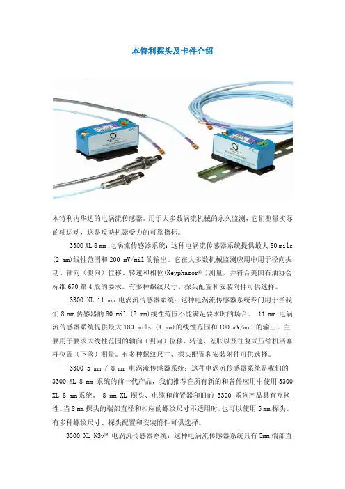
本特利探头及卡件介绍本特利内华达的电涡流传感器。
用于大多数涡流机械的永久监测,它们测量实际的轴运动,这是反映机器受力的可靠指标。
3300 XL 8 mm 电涡流传感器系统:这种电涡流传感器系统提供最大80 mils (2 mm)线性范围和200 mV/mil的输出。
它在大多数机械监测应用中用于径向振动、轴向(侧向)位移、转速和相位(Keyphasor® )测量,并符合美国石油协会标准670第4版的要求。
有多种螺纹尺寸、探头配置和安装附件可供选择。
3300 XL 11 mm 电涡流传感器系统:这种电涡流传感器系统专门用于当我们8 mm传感器的80 mil (2 mm)线性范围不能满足要求时的场合。
11 mm 电涡流传感器系统提供最大180 mils (4 mm)的线性范围和100 mV/mil的输出,主要用于要求大线性范围的轴向(测向)位移、转速、差胀以及往复式压缩机活塞杆位置(下落)测量。
有多种螺纹尺寸、探头配置和安装附件可供选择。
3300 5 mm / 8 mm 电涡流传感器系统:这种电涡流传感器系统是我们的3300 XL 8 mm 系统的前一代产品,我们推荐在所有新的和备件应用中使用3300 XL 8 mm系统。
8 mm XL 探头、电缆和前置器和旧的 3300 系列产品具有互换性。
当8 mm探头的端部直径和相应的螺纹尺寸不适用时,也可以使用5 mm探头。
有多种螺纹尺寸、探头配置和安装附件可供选择。
3300 XL NSv™ 电涡流传感器系统:这种电涡流传感器系统具有5mm端部直径和60 mils (1.5 mm)的更短线性范围,适用于被测靶面区域小、侧视或沉孔间隙减小以及其它限制使用我们标准的 5 mm / 8 mm 电涡流传感器的情况。
3300 16 mm 高温电涡流传感器系统:这种电涡流传感器系统用于最高350℃ (662°F)的高温环境,如温度超过我们标准电涡流探头和电缆能够承受的极限的某些燃气和蒸汽轮机应用。
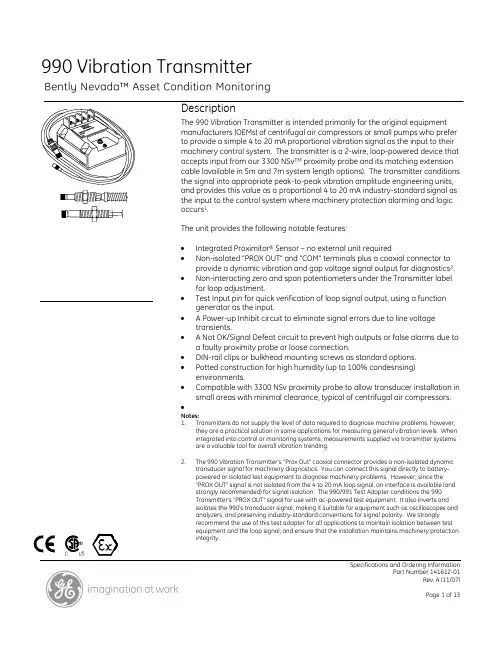
Specifications and Ordering InformationPart Number 141612-01Rev. A (11/07)990 Vibration TransmitterDescriptionThe 990 Vibration Transmitter is intended primarily for the original equipment manufacturers (OEMs) of centrifugal air compressors or small pumps who prefer to provide a simple 4 to 20 mA proportional vibration signal as the input to their machinery control system. The transmitter is a 2-wire, loop-powered device that accepts input from our 3300 NSv TM proximity probe and its matching extension cable (available in 5m and 7m system length options). The transmitter conditions the signal into appropriate peak-to-peak vibration amplitude engineering units, and provides this value as a proportional 4 to 20 mA industry-standard signal as the input to the control system where machinery protection alarming and logic occurs 1.The unit provides the following notable features:• Integrated Proximitor ® Sensor – no external unit required• Non-isolated “PROX OUT" and "COM" terminals plus a coaxial connector toprovide a dynamic vibration and gap voltage signal output for diagnostics 2. • Non-interacting zero and span potentiometers under the Transmitter labelfor loop adjustment.• Test Input pin for quick verification of loop signal output, using a functiongenerator as the input.• A Power-up Inhibit circuit to eliminate signal errors due to line voltagetransients.• A Not OK/Signal Defeat circuit to prevent high outputs or false alarms due toa faulty proximity probe or loose connection.• DIN-rail clips or bulkhead mounting screws as standard options. • Potted construction for high humidity (up to 100% condesnsing)environments.• Compatible with 3300 NSv proximity probe to allow transducer installation insmall areas with minimal clearance, typical of centrifugal air compressors. •Notes:1. Transmitters do not supply the level of data required to diagnose machine problems, however,they are a practical solution in some applications for measuring general vibration levels. When integrated into control or monitoring systems, measurements supplied via transmitter systems are a valuable tool for overall vibration trending.2. The 990 Vibration Transmitter's "Prox Out" coaxial connector provides a non-isolated dynamictransducer signal for machinery diagnostics. You can connect this signal directly to battery-powered or isolated test equipment to diagnose machinery problems. However, since the "PROX OUT" signal is not isolated from the 4 to 20 mA loop signal, an interface is available (and strongly recommended) for signal isolation. The 990/991 Test Adapter conditions the 990 Transmitter's "PROX OUT" signal for use with ac-powered test equipment. It also inverts and isolates the 990's transducer signal, making it suitable for equipment such as oscilloscopes and analyzers, and preserving industry-standard conventions for signal polarity. We strongly recommend the use of this test adapter for all applications to maintain isolation between test equipment and the loop signal, and ensure that the installation maintains machinery protection integrity.SpecificationsUnless otherwise noted, the following specifications apply at +22°C (+72°F) using a 3300 NSv Probe and Extension Cable, and an AISI 4140 steel target. ElectricalInput:Accepts one non-contacting 3300NSv Proximity Probe andextension cable.Power:Requires +17 Vdc to +35 Vdcexternal power supply.4-20 mA SignalOutput:4-20 mAdc over specified full-scale range in 2-wireconfiguration.4-20 mA LoopAccuracy:Within ±1.5% over specified full-scale range. Accuracy is ratedfrom the TEST signal input to thevoltage measured across a 250 Ωloop resistance.Probe GapProbe must be gapped between0.5 and 1.75 mm (20 and 55 mils)from target to ensure full scalerange.Maximum LoopResistance:1,000 Ω including cable at 35 Vdc. CurrentLimiting:23 mA typical.Zero and Span:Non-interacting externaladjustments. NOT OK/SignalDefeat:Signal output will go to less than3.6 mA within 100 µs after a NotOK condition occurs. Signaloutput is restored within 2-3seconds after the NOT OKcondition is removed.Power-upInhibit:Signal output stays at less than3.6 mA for 2 to 3 seconds afterpower is applied.ProximitorSensor Output:Compatible with ungrounded,portable test equipment. Whenusing grounded, ac-powered testequipment, use the 122115-01Test Adapter for signal isolation. OutputImpedance:Prox Out has a 10 kΩ outputimpedance calibrated for a 10MΩ load.Prox OutLinear Range:1.4 mm (55 mils). Begins atapproximately 0.25 mm (10 mils)from target surface.Prox OutIncrementalScale Factor:7.87 mV/µm (200 mV/mil) ±6.5%typical includinginterchangeability errors whenmeasured in increments of 0.25mm (10 mils) over the linear rangeusing a flat 30 mm (1.2 inch)target.TemperatureStability:Incremental scale factor remainswithin ±10% of 7.87 mV/µm (200mV/mil) from 0 °C to +70 °C (+32°F to +158 °F).Specifications and Ordering InformationFrequencyResponse:5 Hz to 6,000 Hz +0, -3 dB. MinimumTarget Size:9.5 mm (0.375 in) diameter. LeadwireLength:Non-Hazardous, Zone 2 or Div 2Hazardous area locations: 13 km(8 miles) maximum betweentransmitter and receiving devicefor signal output.Intrinsically Safe Hazardous arealocations: 68 metres (225 ft.)maximum between transmitterand receiving device for signaloutput.Maximum for Proximitor SensorOutput, maximum cable distanceis 3 metres (10 feet).ElectricalClassification:General Purpose Approval byCanadian Standards Association(CSA/NRTL/C) in North Americaand by VDE in Europe. 990 hasthe CE mark for Europe. Hazardous Area ApprovalsCSA/NRTL/CClass I, Div 2Groups A, B, C, DT5 @ Ta = 85 °C, Type 41675219 (LR 26744-151)Per Drawing 128838ATEXII 1 GEEx ia IIC T4LCIE 06 ATEX 6052 XT4 @ -35°C ≤ Ta ≤ +85°CII 3 GEEx nA IIC T4LCIE 06 ATEX 6055 XT4 @ -35°C ≤ Ta ≤ +85°C Maritime ApprovalsAmerican Bureau of Shipping (ABS)Type ApprovalCertificationNumber06-HS177078/1-PDA Environmental LimitsTransmitterTemperatureOperatingTemperature:AgencyApprovaloptions = 00, 010 °C to +70 °C (+32 °F to +158 °F)AgencyApprovaloptions = 05-35 °C to +85 °C (-31 °F to +185°F)StorageTemperature:-51 °C to +100 °C (-60 °F to +212°F).ProbeTemperatureOperatingTemperature:-35 °C to +177 °C (-31 °F to +350°F).StorageTemperature:-51 °C to +177 °C (-60 °F to +350°F).Specifications and Ordering InformationRelativehumidity:100% condensing, non-submerged, with protection ofcoaxial connectors. MechanicalTransducer TipMaterial:Polyphenylene sulfide (PPS). TransducerCase Material:AISI 303 or 304 Stainless Steel(SST).Probe Cable:75Ω coaxial, fluoroethylenepropylene (FEP) insulated.Cable Armor(optional):Flexible AISI 302 SST with optionalFEP outer jacket.TensileStrength:22 kg (50 lbs) tip to cable,maximum.TransmitterWeight:0.43 kg (0.9 lbs).Total SystemWeight:0.82 kg (1.8 lbs) typical. Ordering Information990-AXX-BXX-CXX-DXXA: Full-scale Option0 4 0-4 mils pp (0-100 mm pp)0 50-5 mils pp (0-125 mm pp) B: System Length Option5 0 5.0 metres (16.4 feet)7 07.0 metres (23.0 feet)C: Mounting Option0 135 mm DIN rail clips0 2 Bulkheadscrews0 3 DIN clips and screwsD: Agency Approval Option0 0 Notrequired0 1 CSA Division 2 NRTL/C0 5ATEX Zone 0, ATEX Zone 2 andincludes ABS maritimeapproval3300 NSv Proximity Probes3309013300 NSv Probe, 1/4-28 UNFthread, without armor. 3309023300 NSv Probe, 1/4-28 UNFthread, with armor.3309083300 NSv Probe, 3/8-24 UNFthread, without armor. 3309093300 NSv Probe, 3/8-24 UNFthread, with armor.Part Number-AXX-BXX-CXX-DXX-EXXOption DescriptionsA: Unthreaded Length OptionNote: Unthreaded length must be at least0.7 in less than the case length.Length configurations:Minimum length: 0 inMaximum length: 9.2 inExample:0 4 = 0.4 inB: Case Length OptionOrder in increments of 0.1 inThreaded length configurations:Minimum length: 0.8 inMaximum length: 9.9 inExample: 3 5 = 3.5 inC: Total Length Option0 50.5 metre (1.67 feet)1 0 1.0 metre (3.25 feet)5 0 5.0 metres (16.4 feet)7 0 7.0 metres (23 feet)D: Connector Option0 1 Miniature coaxial ClickLoc™connector with connectorprotector, standard cable0 2 Miniature coaxial ClickLocconnector, standard cableSpecifications and Ordering Information1 1 Miniature coaxial ClickLocconnector with connectorprotector, FluidLoc® Cable1 2 Miniature coaxial ClickLocconnector, FluidLoc Cable E: Agency Approval Option0 0 Not required0 5 M ultiple Approvals (CSANRTL/C andBASEEFA/CENELEC, whichincludes CSA Division 2) 3300 NSv Probes, Metric3309033300 NSv Probe, M8 x 1 thread,without armor.3309043300 NSv Probe, M8 x 1 thread,with armor.3309053300 NSv Probe, M10 x 1 thread,without armor.3309103300 NSv Probe, M10 x 1 thread,with armor.Part Number-AXX-BXX-CXX-DXX-EXXOption DescriptionsA: Unthreaded Length OptionNote: Unthreaded length must be at least20 mm less than the case length.Order in increments of 10 mmUntreaded length configurations:Minimum length: 0 mmMaximum length: 230 mmExample:0 6 = 60 mmB: Case Length OptionOrder in increments of 10 mmMinimum length: 20 mmMaximum length: 250 mmExample: 2 5 = 250 mmC: Total Length Option0 50.5 metre (20 in)1 0 1.0 metre (39 in)5 0 5.0 metre (16.4 feet)7 0 7.0 metre (23 feet) D: Connector Option0 1 Miniature coaxial ClickLocconnector with connectorprotector, standard cable0 2 Miniature coaxial ClickLocconnector, standard cable1 1 Miniature coaxial ClickLocconnector with connectorprotector, FluidLoc Cable1 2 Miniature coaxial ClickLocconnector attached, FluidLocCableE: Agency Approval Option0 0 Notrequired0 5Multiple Approvals (CSANRTL/C andBASEEFA/CENELEC, whichincludes CSA Division 2) 3300 NSv Reverse Mount Probe330906-02-12-CXX-DXX-EXX, 3/8-24 UNF threads 330907-05-30-CXX-DXX-EXX, M10 x 1 UNF threads Option DescriptionsC: Total Length Option0 50.5 metre (20 in)1 0 1.0 metre (39 in)5 0 5.0 metre (16.4 feet)7 0 7.0 metre (23 feet)D: Connector Option0 2 Miniature coaxial ClickLocconnector, standard cable12 Miniature coaxial ClickLocconnector attached, FluidLocCableE: Agency Approval Option0 0 Notrequired0 5Multiple Approvals (CSANRTL/C andBASEEFA/CENELEC, whichincludes CSA Division 2) Extension Cable330930-AXXX-BXX-CXXA: Cable Length Option0 4 0 4.0 metres (13.1 feet)0 4 5 4.5 metres (14.8 feet)0 6 0 6.0 metres (19.7 feet)0 6 5 6.5 metres (21.3 feet)Specifications and Ordering InformationB: Armor Option0 0Without stainless steel armor0 1 With FEP covered stainlesssteel armor0 2With stainless steel armor0 3Without stainless steel armor,with connector protector0 4With FEP covered stainlesssteel armor and connectorprotector0 5With stainless steel armor andconnector protectorC: Agency Approval Option0 0 NotRequired0 5 Multiple Approvals (CSANRTL/C and BASEEFA/CENELEC(which includes CSA Division 2) Accessories122115-01990/991 Test Adapter. Packageincludes: 990/991 Test Adapter,9V battery, Universal ac Adapter,Power Cord (North American),User Guide and Soft CarryingCase.The 990/991 Test Adapter invertsand isolates the PROX OUT signalfrom the 990 Transmitter so thatyou can connect 990 Transmittersto ac-powered diagnosticequipment. The Adapter modifiesthe PROX OUT signal so that itmatches our standard proximitorsensor signals by performingthese functions:• Shifts the phase of thePROX OUT signal by 180by changing the voltagefrom positive to negative• Isolates the transmitterfrom diagnosticequipment so thatequipment with differentgrounds will not affectthe transmitter's 4-20 mAloop signal• Reduces noise in thesurrounding area fromaffecting the PROX OUTsignalThe 990/991 Test Adapterprovides the following benefits:• Small size and weight forportable operation• Battery or ac adapterpower options• Automatic shutoff circuitthat powers the unitdown when the battery islow• Two channels, so anOrbit can be displayedfor XY probeconfigurations.990/991 Test Adapter Accessories123266-01Coaxial Cable Kit. Includes 4cables with length of 1.5 metres(5 feet) each.02211505Single coaxial cable with lengthof 1.5 metres (5 feet).990/991 Test Adapter Spare Parts01810700Battery (9 volt alkaline). 02270056Ac adapter. Has universal acinput to 9 volts dc output. Input is108 to 132 Vac with 120 Vacnominal, or 207 to 253 Vac with240 Vac nominal.02198937Power cord (for North Americanac power outlet).123133-01User Guide.Specifications and Ordering InformationProbe and Transmitter Accessories 02173006Bulk cable (specify length infeet). 1.0 mm2 (18 AWG),2-conductor, twisted, shieldedcable used for the 4 to 20 mAloop. Also used for the PROX OUTsignal on the 990 Transmitter'sterminal strip.123655-01Manual.330153-05Cable Connector Kit. PackageIncludes 1 set of 75 Ω miniaturemale and female connectors,shrink tubing and 3300 IsolatorSeal for protection of coaxialconnectors.163356Connector Crimp Tool Kit.Includes one set of 75 Ω ClickLocinserts and connector installationinstructions. Supplied withcarrying case.330951-01990 Mounting Screws (spares).Contains 4 screws.124115-01DIN rail mounting clip. Installedon the 990 Transmitter to allowmounting on 35 mm DIN rail.Specifications and Ordering InformationDimensional drawingsNote: All dimensions shown in millimetres (inches) unless noted otherwise.1. Mounting holes, 5.8 mm (0.23 in) diameter, 4 places2. Bulkhead mount holes, 4 each. 6-32 x 1.326 screws provided when mounting option specifiedFigure 1: 990 Vibration Transmitter Dimensions (Top View)DIN mount clips when DIN rail mounting is specifiedFigure 2: 990 Vibration Transmitter Dimensions (Side View)Specifications and Ordering Information1. Probe tip, 5.26 mm (0.207 in) maximum diameter2. Hexagonal nut3. Case Thread4. Wrench flats5. 75Ω cable, 2.8 mm (0.11 in ) maximim outside diameter, 7.6 mm (0.30 in) maximum outside diameter of armor6. Miniature male coaxial connector,7.23 mm (0.285 in) maximum outside diameter “D”7. Unthreaded length “A”8. Case length “B”9. 2.92 mm (0.115 in) maximum10. Total length “C”, +30%, -0%Figure 3: 3300 NSv Proximity probes, Standard Mount330901, 1/4-28 UNF-2A, without armor330902, 1/4-28 UNF-2A, with armor330903, M8x1 thread, without armor330904, M8x1 thread, with armor330905, M10x1 thread, without armor330908, 3/8-24 UNF-2A, without armor330909, 3/8-24 UNF-2A, with armor330910, M10x1 thread, with armorNotes:Standard mount 1/4-28 UNF thread probes are supplied with a 7/16 inch lock nut and 7/32 inch wrench flats.Standard mount M8x1 thread probes are supplied with a 13 mm lock nut and 7 mm wrench flats.Standard mount 3/8-28 UNF thread probes are supplied with a 9/16 inch lock nut and 5/16 inch wrench flats.Standard mount M10x1 thread probes are supplied with a 17 mm lock nut and 8 mm wrench flats.Specifications and Ordering Information3. 51.1 mm (2.01 in) maximum4. Connector protector (fluorosilicone material)Figure 4: Installed Connector Protectors1. Probe tip, 5.26 mm (0.207 in) maximum diameter2. Hexagonal nut3. Case thread4. 75Ω cable, 2.8 mm (0.11 in) outside diameter5. Miniature male coaxial connector, 7.23 mm (0.285 in) maximum outside diameter “D”6. 5.08 mm (0.20 in)7. Unthreaded case length “A”, 5.08 mm (0.20 in)8. Case length “B”, 30.48 mm (1.20 in)9. 2.92 mm (0.115 in) maximum10. Total length “C”, +30%, -0%Figure 5: 3300 NSv Proximity Probes, Reverse Mount330906, 3/8-24 UNF-2A330907, M10x1 threadNotes:Reverse mount probes are not available with armor or connector protector options.Specifications and Ordering Information1.2.3.5. Stainless steel ferrules, 8.4 mm (0.33 in) diameter6. FEP-insulated coaxial cable7. Miniature female coaxial connector8. Cable length +20%, -0%Figure 6: 3300 NSv Extension CableNotes:Stainless steel armor is supplied with or without FEP outer jacket.Specifications and Ordering Information1. To test adapter 122115-012. Receiver3. Cable shield4. Transmitter5. Extension cable6. Recommended wiring is shielded, twisted-pair, 1.0 mm (18 AWG) (part number 02173006). Maximum length is 13 km (8 miles).7. Power supply, V PS = 17 to 35 Vdc8. Common (ground)9. ProbeApplication AdvisoryThe phase of the PROX OUT signal is inverted from the standardfor Bently Nevada LLC products. Also, connecting grounded ac-powered equipment to PROX OUT may result in a false alarm.Use test adapter 122115-01 to connect ac equipment to thetransmitter. Note that the 122115-01 also inverts the PROX OUTsignal.Figure 7: 990 Vibration Transmitter loop wiring connectionsSpecifications and Ordering Information1. Maximum loop resistance in ohms2. Power supply voltage V PS3. Operating regionNote: R LOOP = 43.5 x (V ps - 12) Ω maximum. If the maximum loop resistance is exceeded, then the full scale current will not reach20 mA.Figure 8: 990 Vibration Transmitter maximum loop resistanceCopyright 2006. Bently Nevada LLC.1631 Bently Parkway South, Minden, Nevada USA 89423Phone: 775.782.3611 Fax: 775.215.2873/bentlyAll rights reserved.Bently Nevada, Proximitor, NSv, ClickLoc, and FluidLoc are trademarks of General Electric Company.Specifications and Ordering Information。
TSI系统调试基本知识本内容将围绕大多数电厂中广泛使用的美国本特利(BENTLY)公司生产的振动检测系统3500为模版,全面讲述系统安装、组态、调试过程及调试中常见问题的处理。
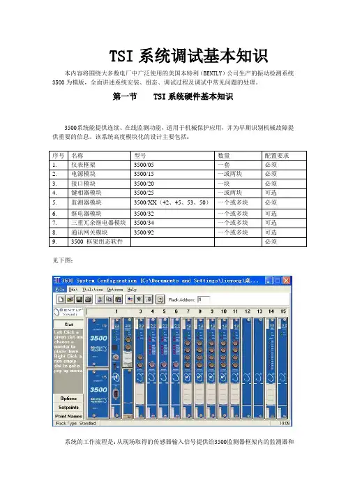
第一节 TSI系统硬件基本知识3500系统能提供连续、在线监测功能,适用于机械保护应用,并为早期识别机械故障提供重要的信息。
该系统高度模块化的设计主要包括:见下图:系统的工作流程是:从现场取得的传感器输入信号提供给3500监测器框架内的监测器和键相位通道,数据被采集后,与报警点比较并从监测器框架送到一个地方或多个地方处理。
3500框架中模件的共同特征是带电插拔和内部、外部接线端子。
任何主模件(安装在3500框架前端)能够在系统供电状态中拆除和更换而不影响不相关模块的工作,如果框架有两个电源,插拔其中一块电源不会影响3500框架的工作。
外部端子使用多芯电缆(每个模块一根线)把输入\输出模块与终端连接起来,这些终端设备使得在紧密空间内把多条线与框架连接起来变的非常容易,内部端子则用于把传感器与输入\输出模块直接连接起来。
外部端子块一般不能与内部端子输入/输出模块一起使用。
1、3500/05系统框架3500框架用于安装所有的监测器模块和框架电源。
它为3500各个框架之间的互相通讯提供背板通讯,并为每个模块提供所要求的电源。
3500框架有两种尺寸:1 全尺寸框架——19英寸EIA框架,有14个可用模块插槽2 迷你型框架——12英寸框架,有7个可用模块插槽电源和框架接口模块必须安装于最左边的两个插槽中。
其余14个框架位置(对与迷你型框架来说是其余7个位置)可以安装任何模块。
2、3500/15电源模块3500 电源是半高度模块,必须安装在框架左边特殊设计的槽口内。
3500 框架可装有一个或两个电源(交流或直流的任意组合)。
其中任何一个电源都可给整个框架供电。
如果安装两个电源,第二个电源可做为第一个电源的备份。
当安装两个电源时,上边的电源作为主电源,下边的电源作为备用电源,只要装有一个电源,拆除或安装第二个电源模块将不影响框架的运行。
燃气轮机汽轮机保护装置采用的是美国本特利(BENTLY)公司生产的3500保护系统,该系统是计算机化的振动信息系统,可对旋转机械和往复式运动机械的机械状态提供所需要的信息,如不平衡、不对中,轴裂纹和轴承故障等机械问题的早期判定提供可靠依据。
本套安全监视装置用于连续监视机组本体各种参数,其监视参数有转速、轴向位移、胀差汽轮机转子与汽缸的相对膨胀,称为胀差。
习惯上规定转子膨胀大于汽缸膨胀时的胀差值为正胀差,汽缸膨胀大于转子膨胀时的胀差值为负胀差。
根据汽缸分类又可分为高差、中差、低I差、低II差。
胀差数值是很重要的运行参数,若胀差超限,则热工保护动作使主机脱扣。
使胀差向正值增大的主要因素简述如下:1)启动时暖机时间太短,升速太快或升负荷太快。
2)汽缸夹层、法兰加热装置的加热汽温太低或流量较低,引起汽加热的作用较弱。
3)滑销系统或轴承台板的滑动性能差,易卡涩。
4)轴封汽温度过高或轴封供汽量过大,引起轴颈过份伸长。
5)机组启动时,进汽压力、温度、流量等参数过高。
6)推力轴承磨损,轴向位移增大。
7)汽缸保温层的保温效果不佳或保温层脱落,在严禁季节里,汽机房室温太低或有穿堂冷风。
8)双层缸的夹层中流入冷汽(或冷水)。
9)胀差指示器零点不准或触点磨损,引起数字偏差。
10)多转子机组,相邻转子胀差变化带来的互相影响。
11)真空变化的影响。
12)转速变化的影响。
13)各级抽汽量变化的影响,若一级抽汽停用,则影响高差很明显。
14)轴承油温太高。
15)机组停机惰走过程中由于“泊桑效应”的影响。
使胀差向负值增大的主要原因:1)负荷迅速下降或突然甩负荷。
2)主汽温骤减或启动时的进汽温度低于金属温度。
3)水冲击。
4)汽缸夹、法兰加热装置加热过度。
5)轴封汽温度太低。
6)轴向位移变化。
7)轴承油温太低。
8)启动进转速突升,由于转子在离心力的作用下轴向尺寸缩小,尤其低差变化明显。
9)汽缸夹层中流入高温蒸汽,可能来自汽加热装置,也可能来自进汽套管的漏汽或者轴封漏汽。

2个点来描述Bently本特利振动传感器的接收原理2个点来描述Bently本特利振动传感器的接收原理,详情如下:Bently本特利振动传感器并不是直接将原始要测的机械量转变为电量,而是将原始要测的机械量做为Bently本特利振动传感器的输入量,然后由机械接收部分加以接收,形成另一个适合于变换的机械量,由机电变换部分再将变换为电量。
因此一个传感器的工作性能是由机械接收部分和机电变换部分的工作性能来决定的。
1、Bently本特利振动传感器相对式机械接收原理由于机械运动是物质运动的简单的形式,因此人们先想到的是用机械方法测量振动,从而制造出了机械式测振仪(如盖格尔测振仪等)。
传感器的机械接收原理就是建立在此基础上的。
相对式测振仪的工作接收原理是在测量时,把仪器固定在不动的支架上,使触杆与被测物体的振动方向一致,并借弹簧的弹性力与被测物体表面相接触,当物体振动时,触杆就跟随它一起运动,并推动记录笔杆在移动的纸带上描绘出振动物体的位移随时间的变化曲线,根据这个记录曲线可以计算出位移的大小及频率等参数。
由此可知,相对式机械接收部分所测得的结果是被测物体相对于参考体的相对振动,只有当参考体绝对不动时,才能测得被测物体的绝对振动。
这样,就发生一个问题,当需要测的是绝对振动,但又找不到不动的参考点时,这类仪器就无用武之地。
例如:在行驶的内燃机车上测试内燃机车的振动,在地震时测量地面及楼房的振动……,都不存在一个不动的参考点。
在这种情况下,我们必须用另一种测量方式的测振仪进行测量,即利用惯性式测振仪。
2、Bently本特利振动传感器惯性式机械接收原理惯性式机械测振仪测振时,是将测振仪直接固定在被测振动物体的测点上,当传感器外壳随被测振动物体运动时,由弹性支承的惯性质量块将与外壳发生相对运动,则装在质量块上的记录笔就可记录下质量元件与外壳的相对振动位移幅值,然后利用惯性质量块与外壳的相对振动位移的关系式,即可求出被测物体的绝对振动位移波形。

型振动传感器校准仪可校准多种类型的振动传感器,如压电式加速度传感器、磁电式速度传感器及电涡流式传感器,也可对由上述传感器所组成的各种振动测试仪表、振动监测系统及数据采集系统进行校准。
该校准仪内部可产生 、 、 、 、 、 、 及 等八种频率的标准正弦信号。
所输出的加速度、速度及位移三种振动的幅值可通过电位器改变,并由数字显示。
可垂直、水平两个方向使用,以校准垂直、水平传感器。
型振动传感器校准仪集正弦信号发生器、功率放大器、标准传感器和振动台于一身,具有体积小、精度高、操作简单、使用方便等特点,可在现场和实验室使用。

BH5000网络化实时监测诊断系统 ====使用指南 ====版本:V4.6.0.4北京博华信智科技发展有限公司2014年 04月目录1前言 .................................................................................................................. 1 1.1标识 (2)1.2BH5000网络化实时监测系统概 ................................................................... 2 1.2.1实时监测系统功能 .......................................................................................... 2 1.2.2实时监测系统特性 (3)1.3BH5000客户端软件概述 (4)2客户端软件的安装和配置 .............................................................................. 5 2.1客户端软件的安装 (5)2.2客户端软件的配置 (7)3基本操作指南 ................................................................................................ 10 3.1系统登录 ........................................................................................................ 10 3.2界面总览 ........................................................................................................ 10 3.3菜单栏 ............................................................................................................ 11 3.4快捷工具栏 .................................................................................................... 13 3.5功能模块抽屉式菜单栏 ................................................................................ 14 3.6导航栏 ............................................................................................................ 15 3.7绘图工具栏 .................................................................................................... 15 3.8操作页 ............................................................................................................ 16 3.9信息页 ............................................................................................................ 16 3.10图谱操作 ........................................................................................................ 17 3.10.1图谱新增毫秒显示 ........................................................................................ 17 3.10.2游标 ................................................................................................................ 17 3.10.3标注 ................................................................................................................ 17 3.10.4同步标注 ........................................................................................................ 18 3.10.5标点 ................................................................................................................ 18 3.10.6趋势操作 ........................................................................................................ 19 3.10.7复位 ................................................................................................................ 19 3.10.8打印 ................................................................................................................ 20 3.10.9保存图形 ........................................................................................................ 20 3.10.10切换 ................................................................................................................ 21 3.10.11显示报警线 .................................................................................................... 22 3.10.12纵坐标自动调整 ............................................................................................ 22 3.10.13锁定坐标 ........................................................................................................ 23 3.10.14手动修改坐标 (23)3.10.15图谱放大,关联更新 (24)3.10.16滚轮放大 (24)3.10.17自定义图谱布局 (25)3.10.18三维图谱 (26)3.10.19双击时间戳画图 (27)3.11设备树显示报警 ............................................................................................ 27 3.12设备树启停车状态显示 ................................................................................ 27 3.13设备树显示断网状态 .................................................................................... 28 3.14设备切换 ........................................................................................................ 28 3.15背景提示图 .................................................................................................... 29 3.16服务器状态切换 .. (30)3.17设备采集状态设置 (33)4旋转机械专用图谱 ........................................................................................ 34 4.1机组概貌图 .................................................................................................... 34 4.2振动监测 ........................................................................................................ 35 4.3振动历史比较图 ............................................................................................ 37 4.4单多值棒图 .................................................................................................... 38 4.5轴心轨迹 ........................................................................................................ 39 4.6轴心位置 ........................................................................................................ 42 4.7启停车图形 .................................................................................................... 43 4.8综合分析 ........................................................................................................ 45 4.9运行状态图 .................................................................................................... 49 4.10其它参数趋势图 ............................................................................................ 51 4.11全频谱 ............................................................................................................ 52 4.12二维全息谱图 ................................................................................................ 53 4.13三维全息谱图 ................................................................................................ 54 4.14旋转报警查询 (55)4.15现场动平衡 (57)5临时在线专用图谱 ........................................................................................ 59 5.1机组概貌图 .................................................................................................... 59 5.2动平衡响应分析 ............................................................................................ 59 5.3试车分析 ........................................................................................................ 60 5.4振动监测 ........................................................................................................ 62 5.5振动历史比较图 ............................................................................................ 62 5.6单多值棒图 (62)5.7轴心轨迹 (63)5.8轴心位置 ........................................................................................................ 63 5.9综合分析 ........................................................................................................ 63 5.10运行状态图 .................................................................................................... 63 5.11其他参数趋势图 ............................................................................................ 63 5.12旋转报警查询 ................................................................................................ 63 5.13全频谱图 ........................................................................................................ 63 5.14二维全息谱图 ................................................................................................ 63 5.15三维全息谱图 ................................................................................................ 63 5.16现场动平衡 (64)5.17倒谱图 (64)6往复机械专用图谱 ........................................................................................ 64 6.1机组概貌图 .................................................................................................... 64 6.2运行状态图 .................................................................................................... 65 6.3历史比较图 .................................................................................................... 67 6.4单值棒图 ........................................................................................................ 68 6.5活塞杆沉降 /偏摆监测 .................................................................................. 70 6.6活塞杆轨迹图 ................................................................................................ 71 6.7振动监测 ........................................................................................................ 72 6.8多参数分析 .................................................................................................... 74 6.9示功图 ............................................................................................................ 75 6.10综合监测 ........................................................................................................ 76 6.11其它参数趋势图 ............................................................................................ 77 6.12往复报警查询 ................................................................................................ 79 6.13应力监测 (80)6.14冲击诊断 (81)7风电专用图谱 ................................................................................................ 83 7.1机组概貌图 .................................................................................................... 83 7.2趋势分析 ........................................................................................................ 84 7.3冲击诊断 ........................................................................................................ 86 7.4转子类故障诊断 ............................................................................................ 89 7.5倒谱图 ............................................................................................................ 90 7.6单多值棒图 .................................................................................................... 92 7.7其它参数趋势图 ............................................................................................ 93 7.8风电报警查询 (94)8机泵专用图谱 ................................................................................................ 95 8.1机组概貌图 .................................................................................................... 96 8.2趋势分析 ........................................................................................................ 97 8.3冲击诊断 ........................................................................................................ 98 8.4转子类故障诊断 .......................................................................................... 101 8.5倒谱图 .......................................................................................................... 103 8.6单多值棒图 .................................................................................................. 104 8.7其它参数趋势图 (105)8.8机泵报警查询 (106)9在线报告报表 .............................................................................................. 108 9.1监测诊断报告 .............................................................................................. 108 9.2机组月报表 .................................................................................................. 110 9.3厂级报表 ...................................................................................................... 113 9.4振动参数报表 .............................................................................................. 113 10案例库模块 .................................................................................................. 115 10.1案例录入 ...................................................................................................... 115 10.1.1添加案例 ...................................................................................................... 117 10.1.2修改案例 ...................................................................................................... 121 10.1.3取消案例 ...................................................................................................... 121 10.2案例查询 ...................................................................................................... 121 10.2.1案例查询 ...................................................................................................... 122 10.2.2导出word .................................................................................................... 122 10.3案例审核 ...................................................................................................... 123 10.3.1案例查询 ...................................................................................................... 123 10.3.2修改案例 ...................................................................................................... 124 10.3.3审核案例 ...................................................................................................... 124 10.4检维修记录管理 .......................................................................................... 125 10.4.1添加检维修记录 .......................................................................................... 126 10.4.2修改检维修记录 .......................................................................................... 126 10.4.3删除检维修记录 .......................................................................................... 126 10.4.4导出word .................................................................................................... 127 10.5开停车记录管理 .......................................................................................... 127 10.5.1查询原始开停车记录 .................................................................................. 127 10.5.2添加开停车记录 .......................................................................................... 128 10.5.3修改开停车记录 (128)10.5.4删除开停车记录 .......................................................................................... 128 10.5.5开停车记录查询 (129)10.6基于案例诊断 (129)10.6.1诊断条件 (129)10.6.2相似度判断 .................................................................................................. 129 11系统维护和系统故障诊断 .......................................................................... 130 11.1客户端无法登陆 .......................................................................................... 130 11.2客户端看不到概貌图 .................................................................................. 131 11.3客户端提示请选择测点 .............................................................................. 131 11.4添加图谱出错 .............................................................................................. 131 11.5客户端查看不到历史数据库或不保存历史数据 ...................................... 131 11.6客户端图谱单位不正确 .............................................................................. 132 11.7客户端测点缸号不正确 .............................................................................. 132 11.8客户端不报警 .............................................................................................. 132 12附录 .............................................................................................................. 132 12.1旋转机械振动机理和诊断方法 .................................................................. 133 12.1.1机械设备振动监测的主要参数和定义 ...................................................... 133 12.1.2机械设备振动分析常用手段 . (138)1前言状态监测与故障诊断是在设备运行中或在基本不拆卸的情况下, 通过各种手段,掌握设备的运行状态,判定设备产生故障的部位和原因,并预测、预报设备未来的运行状态。
provibtech振动变送器说明书PROVIBTECH派利斯TM016-151-120-00-1。
ProvibTech振动变送器TM016-01:铝导管弯头和减速器,NPT1"到3/4"。
ProvibTech振动变送器TM016-11:带接线端子的铝制导管弯头和减速器。
1"到3/4"NPTI,Div.1,B组,C&D;ClassII,Div.1,E,F&G组和NEMA4X,IP65。
ProvibTech振动变送器TM016-02:带接线端子的不锈钢导管弯头。
1"到3/4"NPTI,Div.1,A,B,C,D和T4组;ClassII,Div.1,E,F&G组和NEMA4X,IP65(与TM016配合使用)。
ProvibTech振动变送器TM016-03:不锈钢法兰安装适配器,带1/2"NPT安装;在直径为38mm(1.5英寸)的圆上有3个7mm的孔。
ProvibTech振动变送器TM0702-XX:铝制MIL连接器,带XX米电缆,直径6.35mm<120°C(250°F)。
ProvibTech振动变送器TM0703-XX:带XX米电缆的密封紧密套管连接器,直径6.35mm<120°C(250°F)。
ProvibTech振动变送器TM0704-XX:不锈钢MIL连接器,带铠装XX米电缆,直径4.83mm<150°C(300°F),比较大长度为10m。
ProvibTech振动变送器TM0705-XX:带有XX米电缆的CorneredMIL连接器,直径6.35mm<120°C(250°F),比较大长度为10m。
ProvibTech涡流传感器TM622-A00-B00-C00-D00-E00-G00。
ProvibTech涡流传感器TM621-A02-B00-C00-D00-E00-G00-10-M1:ProvibTech振动开关VS102-1100-3123。
本特利3300振动指示报警仪1序号仪器名称仪器型号仪器精度1 校验仪1045 0.12 24VDC稳压电源3 TK3-2校验仪23、校验方法:以校验振动值范围0-100um为例,选用8mm探头。
3.1 设备连接方式见下图:3.2 监测器功能3.2.1 OK指示---当前置器输出电压在其上下限之间时(BENTLY为-2——-18V,不同产品的OK电压有所差异,应以说明书为准),OK指示灯点亮,则定义相应传感器处于OK状态。
当A/B通道均处于OK状态或旁路状态时OK继电器才接通。
在周期自检出现异常时,OK指示灯以5Hz频率闪烁;如果上一次复位后传感器出现异常,则OK指示灯以1Hz频率闪烁。
3.2.2延时OK/通道失效——若某通道的信号输入不在OK值的上下限范围内,则该通道的OK LED熄灭,BYPASS LED接通,该通道被关闭;若信号输入恢复正常达30秒,则该通道的OK LED将以1Hz频率闪烁,表示OK状态恢复,BYPASS LED 熄灭并恢复监测功能。
3.2.3 BYPASS LED——若某通道一直处在非OK状态,操作人员可通过设置在监测器线路板上的通道旁路开关使该通道从系统中切除。
通道被旁路或处于延时OK/通道失效状态或用户启动自检,BYPASS LED点亮,该通道失去监测功能。
3.2.4间隙电压——按下面板上的GAP键,从表头的中间刻度读取通道A和B的间隙电压值。
同时按下面板上的GAP和ALERT键可显示间隙电压警告报警点的设置值。
当间隙电压达到或位于间隙电压范围的上限或下限之外并达到6秒时,ALERT LED就会发亮同时相应的警告报警继电器接点就会动作。
3.2.5 报警功能3.2.5.1报警点检查——按下面板上的ALERT和DANGER键,可检查各通道的警告和危险设定点的数值。
3.2.5.2第一报警——警告报警和危险报警具有各自的第一报警电路。
当框架中的监测器具有第一报警功能选择时,若某通道的警告或危险报警为在框架中最先发生,则其相应的报警LED会以闪亮的方式显示。
本特利振动量程-概述说明以及解释1.引言1.1 概述本特利振动量程是描述振动信号幅值范围的一个重要指标。
在振动领域,振动信号的幅值波动范围是评估振动强度和信号质量的重要依据之一。
本特利振动量程定义为信号的最大幅值与最小幅值之间的差值。
振动是一种普遍存在于各个工程领域和科学研究中的物理现象,例如机械系统、电子设备和结构等都会产生振动。
振动信号包含了许多有用的信息,可以用于故障诊断、结构健康监测和性能评估等方面。
而本特利振动量程则是振动信号中的一个关键参数,可以很好地描述信号的强度和幅值分布特征。
测量本特利振动量程的方法和技术有很多种,常用的包括传感器、振动仪和数据采集系统等。
传感器可以将振动信号转换成电信号,通过振动仪或数据采集系统进行采集和分析。
这些仪器设备的精度和稳定性对于准确测量本特利振动量程起着关键作用。
本特利振动量程的应用价值十分广泛。
首先,它可以帮助工程师判断振动信号的强度和稳定性,从而评估机械设备或结构的健康状况。
其次,本特利振动量程还可以用于故障诊断,对于机械设备的故障模式和原因进行判别和分析。
此外,本特利振动量程还可以应用于工程设计和性能评估中,帮助优化设计方案和改进系统性能。
未来,随着科技的不断进步,本特利振动量程的测量方法和技术将得到更大的发展和应用。
例如,基于人工智能和大数据分析的振动信号处理方法将更加智能化和高效化。
同时,新型的传感器和测量设备也将不断涌现,提升本特利振动量程的测量精度和稳定性。
这将为振动领域的研究和应用带来更多新的机遇和挑战。
总结起来,本特利振动量程是振动信号中的重要参数,具有广泛的应用价值。
准确测量和分析本特利振动量程对于工程研究和实践具有重要意义,也是振动领域持续发展的关键之一。
1.2 文章结构本文将按照以下结构来呈现本特利振动量程的研究内容:1. 引言:在此部分中,我们将介绍研究本特利振动量程的背景和意义,以及本文的目的和组织结构。
2. 正文:2.1 本特利振动量程的定义和意义:这部分将详细介绍本特利振动量程的定义和相关概念,并探讨其在工程和科学领域中的重要性和应用价值。
本特利振动探头原理引言:本特利振动探头是一种常用的实验仪器,用于研究物体的振动特性。
它基于本特利原理,通过测量物体的振动频率和振动幅度,可以得到物体的振动特性参数。
本文将详细介绍本特利振动探头的原理和工作方式。
一、本特利原理本特利原理是指当一个物体在振动时,会产生特定频率的声音。
这是因为振动会引起周围空气的压力变化,从而产生声波。
根据本特利原理,我们可以通过测量声波的频率和振幅来了解物体的振动情况。
二、本特利振动探头的结构本特利振动探头由振动传感器和信号处理器组成。
振动传感器通常采用压电陶瓷材料,它可以将物体的振动转化为电信号。
信号处理器则负责对传感器采集到的信号进行放大、滤波和数字化处理。
三、本特利振动探头的工作原理当本特利振动探头靠近一个振动的物体时,振动传感器会受到物体的振动力的作用,产生相应的电信号。
这个电信号经过放大、滤波和数字化处理后,转化为振动的频率和振幅信息。
四、本特利振动探头的应用本特利振动探头广泛应用于机械工程、材料科学和生物医学等领域。
例如,在机械工程中,可以利用本特利振动探头来分析机械设备的振动状况,从而判断设备是否存在故障或磨损。
在材料科学中,可以使用本特利振动探头来研究材料的振动特性,评估材料的质量和性能。
在生物医学中,本特利振动探头可以用来检测人体的生理信号,如心跳和呼吸等。
五、本特利振动探头的优势和局限性本特利振动探头具有以下优势:1. 非接触式测量:本特利振动探头可以远距离测量物体的振动,无需接触被测物体,避免了对物体的干扰。
2. 高灵敏度:本特利振动探头可以测量微小振动,具有较高的灵敏度。
3. 宽频率范围:本特利振动探头可以测量从几十赫兹到几百千赫兹的频率范围。
然而,本特利振动探头也存在一些局限性:1. 受环境干扰:本特利振动探头对周围环境的噪声和干扰较为敏感,需要在实验过程中进行噪声抑制和滤波处理。
2. 有限测量距离:本特利振动探头的测量距离有限,通常在几米到几十米之间。
本特利振动探头原理
本特利振动探头(Bendix test head)是一种用于检测材料的机械性质的探头。
它基于本特利振动原理,通过测量材料在振动状态下的谐振频率来得出材料的一些力学性质。
本特利振动原理是指当一个材料通过振动时,其频率与材料的力学性质有关。
在本特利振动探头中,探头的一端连接到被测材料上,当探头振动时,被测材料也会产生相应的振动。
探头的另一端连接到一个压电传感器上,该传感器可以测量探头的振动频率。
在测量过程中,探头会通过一个外部的激励源进行振动,激励源可以是机械力或电动力。
当探头振动时,通过压电传感器可以测量到探头的谐振频率。
根据本特利振动原理,该谐振频率与被测材料的力学性质,如弹性模量、剪切模量和压缩模量等有关。
测量过程中,通常需要根据被测材料的几何形状和尺寸进行修正计算,以获得准确的力学性质值。
此外,还可以通过测量材料的谐振频率随温度变化的特性,来研究材料的热膨胀性质。
总的来说,本特利振动探头通过测量振动频率来得出材料的力学性质,是一种常用的非破坏性材料测试方法。
它在工业生产和科学研究中具有广泛的应用,可以用于材料的质量检测、材料的设计与开发等。
HY-103E 振动变送器1 概述HY-103E振动变送器是一种固定安装的在线振动测量装置,主要用于对振动速度值的测量。
其输出形式为4mA~20mA标准电流,与振动值的大小成正比。
可直接输入到PLC/DCS中,从而组成一个能对诸如离心泵、往复式压缩机、离心机、冷却塔、工业风机、电动机及燃气轮机等设备进行监测和保护的系统。
本装置采用了传感器与仪器本体一体化的设计。
铸铝外壳和不锈钢构件能防水、防尘,符合工业现场安装和使用的要求。
本装置经国家及仪器仪表防爆安全监督检验站(NEPSI)审查,防爆安全性能符合GB3836.1-2000和GB3836.4-2000标准规定的有关要求。
其防爆标志为Ex ib IIBT4,防爆合格证号为GYB06547X。
本装置必须与隔离式安全栅配套组成本安防爆系统,方可使用于现场存在IIC级以下的爆炸性气体混合体危险场合。
2 技术参数1)最大振动输入:100 mm/s(峰值);2)测量范围:0 mm/s~50 mm/s(峰值);3)测量误差:≤±5%;4)频率响应:2 Hz~500 Hz (-3dB);5)输出形式:4 mA~20 mA 标准电流;6)最大负载电阻:600Ω;7)本安参数:电源回路:Ui=28 V Ii=100 mA Pi=0.7 WCi≈0 μF Li=0.24 mH信号回路:Ui=15 V Ii=150 mA Pi=0.6 WCi=0.4 μF Li=0.24 mH8)电源:额定值DC 24 V,允许范围20 V~28 V;9)外形尺寸:φ72 mm×125 mm;10)质量:约850 g;11)防护等级:IP65,防爆;12)环境温度:-10℃~60℃。
3仪器外型4 基本使用方法1)安装形式见图示。
变送器位置离心泵电动机本装置可直接利用底部的M20×1.5螺栓或经法兰安装座固定在设备的壳体上。
安装时应注意检测的振动方向与本装置銘牌上标志的振动方向一致。
Specifications and Ordering InformationPart Number 177232-01Rev. NC (06/07)Product DescriptionSpecificationsElectricalSensitivity –Main loop(Signal One)0.0 to 25.4 mm/s (0 to 1.0 in/s)± 10%, Broadband R.M.S (rootmean square)[4 mA equals 0.0 mm/s and20 mA equals 25.4 mm/s] Output Format,Ref: Pin A toPin B4 to 20 mA (Current loop),Velocity vibrationExcitationVoltage12 to 30 Vdc (current limited to 40mA)Note: This product is used with PLCs, DCSand SCADA systems that have internalpower supply that are typically currentlimited in the range of 30 mA to 35 mA. Settling Time< 15 seconds (with in 2% of value) ConnectorWiringConventionPin A: 4-20 mA Positive LoopPin B: 4-20 mA Negative Loop andcommon for Dynamic SignalC Pin: Dynamic Signal (in voltage,un-buffered)FrequencyResponse10 Hz to 1 kHz (600 cpm to 60kcpm) ± 10%Sensitivity –Dynamic Signal(Signal Two)10.2 mV/m/s2 (100 mV/g) ± 5% Output Format,Ref: Pin C toPin BVoltage,Acceleration vibration FrequencyResponse2.5 Hz to 10 kHz (150 cpm to 600kcpm) ± 10%Linearity±1%Output Bias(referenced topin-B)2.5v±0.1vFull Scale Range196m/s2 (20 gs) peakVelocity Range420 mm/s (16.5 in/s) peak MountedResonantFrequencyGreater than 12 kHz TransverseSensitivityLess than 5% of sensitivity SensingElement TypeCeramic / ShearSpecifications and Ordering InformationEnvironmental LimitsOperatingTemperatureRange-40 °C to +85 °C(-40 °F to +185 °F)ElectricalIsolation> 108 ohmsIsolationBreakdownVoltage600 Vrms (with less then 1 mAleakage current)ShockSurvivability9,810m/s2 (1,500 g peak),maximum (i.e. drop testNote:: This part is typically mounteddirectly to the machine via a stub. Thisdevice can be used with a mag-base, butcare must be taken to ensure that the unitis not snapped-on to the machine. Thissnapping action can create a very largespike signal that can damage theelectronics. Rolling the mag-base onto themachine greatly reduces this destructivesignal and the unit should not have anyissues.Sensor SealHermetically sealedRelativeHumidity ofTransmitterTo 100% non-submerged Magnetic FieldSensitivity<20 µm/s/gauss (<790µin/s/gauss) peak<14.7 mm/s2 /gauss (< 150 µg/gauss) peak[base on 50 gauss, 50 - 60 Hz] PhysicalWeight131 grams (4.6 ounces), typical Diameter25.4 mm (1.0 in)Height66.0 mm (2.6 in)Case Material304L stainless steelConnector3-pin MIL-C-5015, stainless steel Mounting Holein Body¼-28 UNFMountingThreadsM6 x 1 (SI version)¼-28 UNF (English version) MountingTorque4 to 7 N-m (3 to5 in-lbf) ConnectorWiringConventionPin A: 4-20 mA Positive Loop (withreference to Pin B)Pin B: 4-20 mA Negative Loop andcommon for Dynamic SignalC Pin: Dynamic Signal (in voltage,un-buffered and with reference toPin B)CE Mark DirectivesEMC Directives 89/336/EEC – with amendments Declaration of Conformity available online –/prod/products/certs/certificates.htmIEC/EN61326Radiated EmissionsCISPR 11 Criteria BSpecifications and Ordering InformationESD ImmunityEN 61000-4-2 Criteria BRadiated ImmunityEN 61000-4-3 Criteria BFast Transient ImmunityEN 61000-4-4 Criteria BSurge ImmunityEN 61000-4-5 Criteria AConducted ImmunityEN 61000-4-6 Criteria AMagnetic ImmunityEN 61010-1 Criteria ASafety:Explosive Atmosphere GeneralEN50014Explosive Atmosphere Intrinsic SafetyEN50020CE Product SafetyIEC/EN 61010-1ApprovalsATEXPending, LCIE 05 ATEX 6154 XSpecifications and Ordering InformationSpecifications and Ordering InformationOrdering InformationThe GE Seismic transmitter can be private labeled for our OEM customers. Contact your local service representative for further information.For standard orders use the number provided below. Product Description Seismic Transmitter 177230-02Product DescriptionInterconnect Cable without Armor 16925-AA Option Description A: Length in feetOrder in increments of 1 foot (0.3 m)Minimum length: 12 Feet (3.7 m) Maximum length: 99 Feet (30.2m)Product DescriptionInterconnect Cable with Armor 16710-AA Option Description A: Length in feetOrder in increments of 1 foot (0.3 m)Minimum length: 12 Feet (3.7 m) Maximum length: 99 Feet (30.2m)Accessories (Generic vendors are called out in thissection); The part list below are possible vendor sources for the supporting hardware. The Customer can use this information as reference and select what vendor they wish to use.3-Pin Connector (MIL-C-5015): Base -Cannon (ITT industries):P/N: CA3106R-10SL-3S F97orP/N: MS3106R-10SL-3SShell -Sunbank Co.Glenair, Inc.Contact a vendor with above part number and ask for their part that fits your applicationWire (3-wire with shield):Generic Description: 3 conductor – 18 to 22 AWGcables with a minimum of a of 0.01” think outer jacket and inner wire, and shield with a minimum of 80% coverage. Insulationshould be rated for a minimum of 600v.Mil-W-16878/4 (Type E) Sonic/Thermax 18 AWG -P/N: 18-TE-1930 (3) SXE 22 AWG -P/N: 22-TE-1934 (3) SXE Standard Wire and Cable Co. 18 AWG - P/N: 1100-88T 22 AWG - P/N: 1100-66T Belden18 AWG - P/N: 83336 22 AWG - P/N: 83334.Graphs and FiguresA Positive Loop (4-20 mA) F 1.27 mm (0.050 inches)G 25.4 mm (1.00 inches)B Negative Loop (4-20 mA) andCommon for Dynamic signalC Dynamic Signal H ¼ - 2b UNF – 2B (English)D 3-Pin ML-C-5015 I 25.1 mm (0.990 inches)E 66.0 mm (2.60 inches)Mm (inches)Copyright © 2007 General Electric Company1631 Bently Parkway South, Minden, Nevada USA 89423Specifications and Ordering Information。