AVR XMEGA 库函数驱动简介
- 格式:pdf
- 大小:582.60 KB
- 文档页数:65

51⼊门笔记-(2)常见单⽚机的种类与简介常见单⽚机种类与简介单⽚机从当初的4位发展到8位、32位,甚⾄更⾼,到现在可以说种类繁多⽽且齐全,数量庞⼤,在不同的领域主流的单⽚机有不同,很多设计开发有时候要⾯临很多选择。
下⾯介绍⼏种常⽤的单⽚机:1、51系列单⽚机stc的51单⽚机51单⽚机最初是由Intel始创的8004单⽚机开始,这是8位的单⽚机,特点是:寄存器少,。
很多功能需要外部扩展,像AD转换、PWM专门输出信号等、I/O⼝输出能⼒不强、运⾏速度慢、抗⼲扰能⼒差、功耗⾼、不具备⾃编程能⼒。
但是它的外围电路相对简单,上⼿容易,适合⼊门级,很多⾼校单⽚机都是以51单⽚机教学为主,在⼯业测控系统应⽤很⼴泛。
⽬前⽣产51单⽚机的⼚家有:英特尔、艾德梅尔、西门⼦、华邦以及国产的宏晶等。
2、AVR系列单⽚机arduino nano开发板,芯⽚为avr单⽚机AVR单⽚机是由Atmel公司最初提出,也是8位单⽚机,后来也有16位的,但是与51不⼀样,它内部指令⼤⼤简化,同时内部结构精简,因此速度更快,功能更加强⼤,驱动能⼒⽐51的强,功耗也很低,抗⼲扰能⼒更强,内部有强劲的Flash程序存储器,烧录快捷⽅便,内部集成多种频率的RC振荡器、PWM输出、AD转换、看门狗、上电⾃动复位等功能。
AVR单⽚机有三种系列:1、tiny AVR,这种主要被⽤于需要性能不是很⾼、效率低下以及在⼩封装中使⽤2、mega AVR,这种主要是针对需要加额外外围电路设计的理想选择,⾃编程能⼒强3、Xmega AVR,这种主要是在⾼集成度和低功耗使⽤AVR单⽚机主要应⽤在打印机、空调、电表等控制电路板当中。
3、STM8系列stm8开发板STM8系列是意法半导体公司⽣产的8位的单⽚机。
该型号单⽚机分为STM8A、STM8S、STM8L三个系列。
从2008年STM8发布⾄今已有13年,截⽌到2018年底累计出货量已经超过40亿⽚。
4、STM32系列单⽚机stm32芯⽚STM32系列单⽚机是有ST公司推出的,表⽰ARM Cortex-M内核的32位微控制器,这个芯⽚功能就更强⼤了,光是学习起来就有厚厚的⼀本书,这还不包括实际操作实践,从事软件开发的⼯程师,特别是设计⼤型系统对这个芯⽚⼀定不陌⽣。
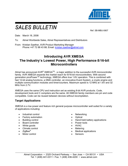
Ref. SB-MBU-0807 Date: March 18, 2008To: Atmel Worldwide Sales, Atmel Representatives and DistributorsFrom: Kristian Saether, AVR Product Marketing ManagerPhone: +47 72 88 43 88; Email: kristian.saether@Introducing AVR XMEGAThe Industry’s Lowest Power, High Performance 8/16-bitMicrocontrollersAtmel has announced AVR® XMEGA TM, a major addition to the successful AVR microcontroller family. AVR XMEGA expands the market reach for 8/16-bit microcontrollers. With second generation picoPower™ technology, XMEGA offers true 1.6V operation. This is combined with fast 12-bit analog functions, a DMA controller, an innovative Event System, a crypto engine and multiple communication modules and timer/counters. Maximum speed is 12 MHz at 1.6V and 32 MHz from 2.7V.XMEGA uses the same CPU and instruction set as existing 8-bit AVR products. Code, development tools and C compilers are the same. All XMEGA family members are pin and code compatible. Code can be reused between devices without recompilation.Target ApplicationsXMEGA is a low power and feature rich general purpose microcontroller well suited for a variety of applications including:• Industrial control • Factory automation • Building control • Board controller • White goods• Climate control • ZigBee®• Motor control • Networking• Optical•Hand-held battery applications • Power tools• HVAC• Metering• Medical applications• SensorsKey Features and BenefitsFeatures BenefitsCPU Performance Single cycle AVR CPU with up to 32 MIPS at 32 MHz, high code density,linear address space, and unmatched performance in the 8/16-bit market Leading in low power AVR XMEGA include 2nd generation picoPower to further extend battery lifefor embedded applications. True 1.6 volt operation means all functionsincluding Flash programming, analog functions, EEPROM and oscillatorsworks in the entire operating range down to 1.6V.Event System Like a reflex in the human body, the innovative XMEGA Event Systemenables inter-peripheral communication without CPU or DMA usage. Thisensures safe fault protection and 100% predictable response time.Direct Memory Access Controller DMA Controller enables fast data transfer that offload the CPU andsignificantly boosts performance. The DMA Controller in XMEGA handlesdata transfer between all combinations of peripherals and data memories,including memory mapped EEPROM.Rich peripheral set XMEGA is equipped with up to eight USARTs, four Serial PeripheralInterfaces (SPIs) and four I2C and SMBus compatible Two Wire Interfaces(TWIs). This gives flexibility for layout and the right communication supportfor embedded applications.Crypto engine The crypto engine supports 1.25 Mbps encrypted data communication.Combined with picoPower technology, AVR XMEGA is the onlymicrocontroller to combine high-speed encrypted data communication withbattery life of 5-10 years.High-end analog modules The XMEGA ADC has 12-bit resolution and is capable of up to 2 millionsamples per second. XMEGA also features 12-bit DAC with up to 1 Mspsconversion rate and up to four flexible analog comparators.Flexible Timer/Counters XMEGA has up to eight 16-bit Timer/Counters with time keeping, frequencywaveform, Pulse Width Modulation (PWM) and input capture capabilities.Compared to competitor solutions with fewer Timer/Counters, XMEGA canhave several time bases in the application. Maximum clock speed for PWMgeneration is 128 MHz.All XMEGA A devices run from 1.6 to 3.6 volt and up to 32 MHz and include:- 4 DMA channels- 8 Event System channels- Crypto engine for AES and DES - 16-bit Real-Time Counter - Brown-out Detector- Watch-Dog Timer- Calibrated Internal RC OscillatorsCompetitionDevice Atmel AVRXMEGA ANEC78K0RRenesasM16CTexasInstrumentsMSP430F2MicrochipPIC24Voltage 1.6V – 3.6V1.8 |– 5.5V(Analog modules2.3-5.5V)2.7 – 5.5 V1.8 – 3.6V(Analog modules2.2V-3.6V)2.0 –3.6VEvent routingnetwork8 ch - - - -DMA 4 ch - 2 ch 3 ch -ADC 12-bit 2000 ksps 10 bit 165 ksps 10-bit 360 ksps 12-bit 200 ksps 10-bit 500 ksps DAC 12-bit 1000 ksps - 8-bit 330 ksps 12-bit 5 ksps -Power consumptionActive 12 MHz3.6 mA4.2 mA 10 mA 3.6 mA 15 mA Power consumptionpower down0.10 uA 1.1 uA 0.8 uA 0.10 uA 3 uA Freq @ 1.8V 12 MHz 5 MHz - 4.15 MHz -Maximal CPUoperating frequency32 MHz 20 MHz 24 MHz 16 MHz 16 MHzProduct Availability, Price and Ordering InformationProduct Flash SRAM I/O 16-bitTimersSPI/TWI/USART12-bit ADC 12-bit DAC AnalogComparator ATxmega64A1 64 4 78 8 4/4/8 2x8 2x2 4 ATxmega128A1 128 8 78 8 4/4/8 2x8 2x2 4 ATxmega192A1 192 8 78 8 4/4/8 2x8 2x2 4 ATxmega256A1 256 16 78 8 4/4/8 2x8 2x2 4 ATxmega384A1 384 32 78 8 4/4/8 2x8 2x2 4 ATxmega64A3 64 4 50 7 4/2/7 2x8 1x2 4 ATxmega128A3 128 8 50 7 4/2/7 2x8 1x2 4 ATxmega192A3 192 16 50 7 4/2/7 2x8 1x2 4 ATxmega256A3 256 16 50 7 4/2/7 2x8 1x2 4 ATxmega16A4 16 2 36 5 2/2/5 1x12 1x2 2 ATxmega32A4 32 4 36 5 2/2/5 1x12 1x2 2 ATxmega64A4 64 4 36 5 2/2/5 1x12 1x2 2 ATxmega128A4 128 8 36 5 2/2/5 1x12 1x2 2The first devices, ATxmega128A1 and ATxmega64A1 are both offered in 100-pin TQFP and BGA packages and are available for sampling by end of March. Samples orders can be placed now. Volume prices for 10k units are US$3.75 and US$3.50 respectively.Other devices announced will be available latest Q4-2008. Since all XMEGA A devices are hex compatible, development can start now using ATxmega128A1.Application notesA comprehensive collection of application notes may be retrieved at /dyn/products/app_notes.asp?family_id=607.Tools supportAtmel’s AVR Studio 4 provide the XMEGA with a free integrated development environment (IDE) already configured for the GNU tool chain. The STK600 starter kit and JTAGICE mkII debugger is used for prototype development and on-chip debug. For further information on AVR Tools, go to/dyn/products/tools.asp?family_id=607.DocumentationAtmel's AVR XMEGA product information may be retrieved at /xmega . For further information on AVR, go to /avr .Presentation material is available online from the FAE CD on the Atmel intra net.An XMEGA flyer in being printed and should be available from our literature stock early April.SupportFor tools and application support, please contact the hotline avr@ .© 2008 Atmel Corporation. All rights reserved. Atmel ®, logo and combinations thereof, Everywhere You Are ®, AVR ®and others are registered trademarks or trademarks of Atmel Corporation. Other terms and product names may be trademarks of others.。

AVR单片机之ATXMEGA系列的ADC研究本文中的源代码采用CodeVision3.12编辑编译。
采用的MCU 型号是Atxmega128A3U。
实际使用测试运行正常。
1、关于ADCA和ADCB的输入引脚问题输入引脚用于单端和差动输入,内部输入直接内部连接设备。
如果设备含有两个ADC,端口A引脚用于ADCA的ADC0-ADC7,也可用于ADCB的ADC8-ADC15,端口B的引脚用于ADCB的ADC0-ADC7,也可用于ADCA的ADC8-ADC15。
所有输入引脚可作为同相输入,输入引脚ADC0-ADC3可作为不带增益时的反相输入,输入引脚ADC4-ADC7可作为带增益时的反相输入。
注意:ADCA和ADCB的输入引脚ADC0-ADC15的定义位置是不同的。
当使用差动输入时,ADC必须设置位signed模式(有符号模式)。
难怪ADCB没有结果。
原来不能用。
2、ADC转换的触发方式方法ADC转换如果采用自由运行模式free-running, 通道sweep,并且每个通道转换完成产生中断,在中断处理程序中处理转换结果。
那么中断次数会非常多,严重影响程序正常运行。
经过分析后,决定采用软件启动ADC转换,启动指令的发出由TCF0定时器溢出中断程序发出,TCF0溢出频率400Hz,每中断一次启动一次一个ADC通道的转换,8次中断完成ADCA四个通道和ADCB四个通道的启动。
这个中断程序只负责启动ADC转换。
void tcf0_init(void){unsigned char s;// Note: The correct PORTF direction for the Compare Channels// outputs is configured in the ports_init function.// Save interrupts enabled/disabled states=SREG;// Disable interrupts#asm("cli")// Disable and reset the timer/counter just to be suretc0_disable(&TCF0);// Clock source: ClkPer/2TCF0.CTRLA=TC_CLKSEL_DIV2_gc; //设置定时器时钟16MHz// Mode: Normal Operation, Overflow Int./Event on TOP// Compare/Capture on channel A: Off// Compare/Capture on channel B: Off// Compare/Capture on channel C: Off// Compare/Capture on channel D: OffTCF0.CTRLB=(0<<TC0_CCDEN_bp) | (0<<TC0_CCCEN_bp) | (0<<TC0_CCBEN_bp) | (0<<TC0_CCAEN_bp) | TC_WGMODE_NORMAL_gc;// Capture event source: None// Capture event action: NoneTCF0.CTRLD=TC_EVACT_OFF_gc | TC_EVSEL_OFF_gc;// Set Timer/Counter in Normal modeTCF0.CTRLE=TC_BYTEM_NORMAL_gc;// Overflow interrupt: Low Level// Error interrupt: DisabledTCF0.INTCTRLA=TC_ERRINTLVL_OFF_gc | TC_OVFINTLVL_LO_gc;// Compare/Capture channel A interrupt: Disabled// Compare/Capture channel B interrupt: Disabled// Compare/Capture channel C interrupt: Disabled// Compare/Capture channel D interrupt: DisabledTCF0.INTCTRLB=TC_CCDINTLVL_OFF_gc | TC_CCCINTLVL_OFF_gc | TC_CCBINTLVL_OFF_gc | TC_CCAINTLVL_OFF_gc;// High resolution extension: OffHIRESF.CTRLA&= ~HIRES_HREN0_bm;// Clear the interrupt flagsTCF0.INTFLAGS=TCF0.INTFLAGS;// Set Counter registerT=0x0000;// Set Period registerTCF0.PER=0x9C3F; //设置定时器周期2.5ms// Set channel A Compare/Capture registerA=0x0000;// Set channel B Compare/Capture registerB=0x0000;// Set channel C Compare/Capture registerC=0x0000;// Set channel D Compare/Capture registerD=0x0000;// Restore interrupts enabled/disabled stateSREG=s;}// Timer/Counter TCF0 Overflow/Underflow interrupt service routineinterrupt [TCF0_OVF_vect] void tcf0_overflow_isr(void){// Write your code herestatic int flag;if(flag<7) flag++; else flag=0;switch(flag) {case 0: // Start the AD conversion on channel 0ADCA.CH0.CTRL|= 1<<ADC_CH_START_bp; //启动ADCA的通道0break;case 1:ADCA.CH1.CTRL|= 1<<ADC_CH_START_bp;//启动ADCA的通道1break;case 2:ADCA.CH2.CTRL|= 1<<ADC_CH_START_bp;//启动ADCA的通道2break;case 3:ADCA.CH3.CTRL|= 1<<ADC_CH_START_bp;//启动ADCA的通道3break;case 4:ADCB.CH0.CTRL|= 1<<ADC_CH_START_bp;//启动ADCB的通道0break;case 5:ADCB.CH1.CTRL|= 1<<ADC_CH_START_bp;//启动ADCB的通道1break;case 6:ADCB.CH2.CTRL|= 1<<ADC_CH_START_bp;//启动ADCB的通道2break;case 7:ADCB.CH3.CTRL|= 1<<ADC_CH_START_bp;//启动ADCB的通道3break;default:break;}}3、ADC转换结果通过DMA方式直接写入内存由DMA由四个独立的通道,这里只用两个通道:通道0和通道1。

AVR单片机的全功能工业控制器设计吴焕琅深圳市中天越华自动控制科技有限公司摘要:介绍一款工业级的实用全功能控制器。
该控制器能隔离采集多种输入信号,输出多种控制信号;具有实时时钟、历史数据存储功能,彩色液晶显示界面,带有触摸屏操作和远程通信接口。
核心部分CPU采用AVR ATmega128单片机。
目前已用于批量生产。
关键词:隔离采集控制单片机彩色显示485接口ATmega128DS1642引言在自动控制产品的设计过程中,实现方案的选择常常是很矛盾的。
使用可编程逻辑控制器(PLC)和人机界面(HMI)来实现,开发速度较快,但成本太高,所开发的产品没有市场竞争力;使用单片机开发,成本低但开发周期长、开发量大且通用性不好。
用户需要的是一种成本低、开发周期较短、通用性较好的控制器,因此全功能工业控制器有很大的应用市场。
全功能工业控制器的整个电路分为信号隔离输入部分、控制器输出部分、实时时钟与历史数据存储部分、彩色液晶显示和触摸屏控制部分、通信接口等。
1信号隔离输入电路信号隔离输入电路分为开关量隔离输入、模拟量隔离输入、高速电脉冲隔离输入,电路如图1所示,开关量的隔离输入较为简单,输入信号采用光耦进行隔离后送入单片的普通I/O,单片机用查询方式进行采集。
图1信号隔离输入电路高速电脉冲的采集需要注意的是,所设计的电路必须适应高速信号采集的要求,因此隔离光耦应采用高速光耦(如6N137等)。
采用查询方式采集高速脉冲容易造成采集数据的丢失,高速脉冲应采用中断方式进行采集。
模拟量隔离采集是本控制器的一个重点和难点,笔者之前采用了线性光耦等多种方式进行模拟量的隔离采集实验,均未获满意的效果。
这里采用一种先将模拟量数字化(使用AD7705),然后通过有光耦隔离的数据口送到CPU进行模拟量隔离采集的方式,效果理想。
2控制器输出电路控制器的输出方式有继电器输出、晶体管输出、模拟电压输出,如图2所示。
继电器输出和晶体管输出电路较为简单,这里不作详细的介绍。
ATmega16 简介ATmega16是基于增强的AVR RISC结构的低功耗8 位CMOS微控制器。
由于其先进的指令集以及单时钟周期指令执行时间,ATmega16 的数据吞吐率高达1 MIPS/MHz,从而可以缓减系统在功耗和处理速度之间的矛盾。
ATmega16 AVR 内核具有丰富的指令集和32 个通用工作寄存器。
所有的寄存器都直接与算逻单元(ALU) 相连接,使得一条指令可以在一个时钟周期内同时访问两个独立的寄存器。
这种结构大大提高了代码效率,并且具有比普通的CISC 微控制器最高至10 倍的数据吞吐率。
ATmega16 有如下特点:16K字节的系统内可编程Flash(具有同时读写的能力,即RWW),512 字节EEPROM,1K 字节SRAM,32 个通用I/O 口线,32 个通用工作寄存器,用于边界扫描的JTAG 接口,支持片内调试与编程,三个具有比较模式的灵活的定时器/ 计数器(T/C),片内/外中断,可编程串行USART,有起始条件检测器的通用串行接口,8路10位具有可选差分输入级可编程增益(TQFP 封装) 的ADC ,具有片内振荡器的可编程看门狗定时器,一个SPI 串行端口,以及六个可以通过软件进行选择的省电模式。
工作于空闲模式时CPU 停止工作,而USART、两线接口、A/D 转换器、SRAM、T/C、SPI 端口以及中断系统继续工作;掉电模式时晶体振荡器停止振荡,所有功能除了中断和硬件复位之外都停止工作;在省电模式下,异步定时器继续运行,允许用户保持一个时间基准,而其余功能模块处于休眠状态; ADC 噪声抑制模式时终止CPU 和除了异步定时器与ADC 以外所有I/O 模块的工作,以降低ADC 转换时的开关噪声; Standby 模式下只有晶体或谐振振荡器运行,其余功能模块处于休眠状态,使得器件只消耗极少的电流,同时具有快速启动能力;扩展Standby 模式下则允许振荡器和异步定时器继续工作。
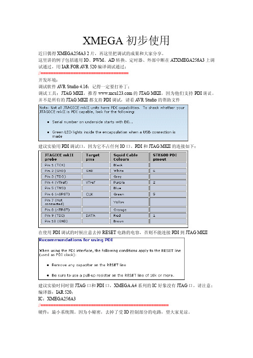
XMEGA128学习笔记1-bootloader下载程序首先需要感谢AVR和与非网举办这次AVR大赛,其次要感谢在学习板申请当中阿呆给予我们小组的帮助,最后要感谢我们的指导老师。
我们小组将在论坛版块连载《XMEGA128学习笔记》系列,分享学习心得与大家共同探讨,也欢迎大家分享自己学习的心得,共同进步。
今天主要是叙述如何使用XMEGA的BOOTLODER功能下载程序。
首先请大家将附近的内容下载,由于论文附件大小的限制,Flip Installer - 3.4.3这个软件分成三个压缩包,需要大家一起解压,解压后进行安装,安装过程大家点击下一步就可以了。
第二个附件是“AVR1927_XMEGA-A1_Xplained_Example_Applications.zip”,这个压缩包是板子的程序和驱动。
大家解压后将“ATxmega128A1.xml”文件拷贝到“X:\Program Files\Atmel\Flip 3.4.3\bin\PartDescriptionFiles”,其中X表示您安装FLIP软件所在的盘符,如图所示:第三步:将XMEGA开发板用USB连接线插入到电脑中,这时候电脑会提示发现新硬件,有驱动需要安装,如图2所示,选择“从列表或指定位置安装(高级)”位置选择“AVR1927_XMEGA-A1_Xplained_Example_Applications\Driver”安装后效果如图4,电脑多个一个虚拟串口,我的电脑显示的是COM8。
第三步:拔掉USB,如何安装板上的SW0按键不放,在插上USB,使得XMEGA进入BOOTLOADER状态。
第四步:打开第一步安装的FLIP软件,首先选择器件和串口的端口,成功后效果如图:这时就可以打开一个HEX文件进行下载,附件中有一个是流水灯的HEX文件,大家下载进去后再复位,看看是不是板上的流水灯在闪烁。
更多参考内容请看《Atmel AVR1927 XMEGA-A1 Xplained Getting Started Guide.pdf》《FLIP软件帮助》今天的内容就到这里,谢谢大家的关注。