格兰富水泵自带变频器操作说明书R操作
- 格式:pdf
- 大小:1.35 MB
- 文档页数:16
HYDRO MPC 启动、运行、维护指导一、启动指导:在启动前,要做到以下几点:机械:1)检查从水箱到主进水口的阀门是否在开的位置。
2)检查水泵进出口阀门,气压罐阀门是否在开的位置。
3)检查传感器和压力表上的阀门是否在开的位置。
4)打开泵上放气螺钉,放气,直到水流平稳地流出后再关闭。
电气检查与操作1)检查控制箱的电源供给是否正常。
2)检查控制箱中各水泵,变频器电源供给开关是否闭合。
3)检查断路器F01(CU352电源供给)是否闭合。
4)检查CU352控制器是否存在报警信息。
若存在报警信息,请根据报警提示排查故障。
5)开机运行,若系统外部管路已排空,开机前请将泵组出口总阀开启1/3,待外部管路充满水后,再全部打开。
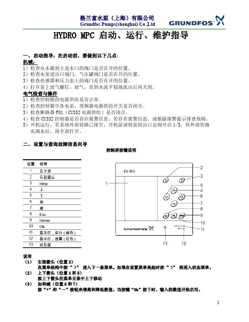
二、设置与查询故障信息向导控制屏按键说明说明(1)右指箭头(位置2)在菜单结构中按”>”进入下一条菜单。
如果在设置菜单亮起时按”>”则进入状态菜单。
(2)上下箭头(位置4和5)按上下箭头在菜单目录中上下移动(3)加和减(位置6和7)按“+”和“—”按钮来增高和降低数值。
当按键“0k”按下时,输入的数值开始启用。
(4)退出(位置8)用“Esc”按钮在菜单中退回到前一页。
如果一个数值已更改,但“Esc”按钮被按下则新数值不会被保存。
如果按“Esc”键前先按“ok”键,则数值会保存。
(5)主页(位置9)按“Home”按钮回到状态菜单(6)“ok”按钮(位置10)“ok”按钮作为输入按钮,“ok”按钮还用来开始参数的设置。
1,开机运行2,设置运行压力4,查看与复位报警5,长期停机操作三、HYDROMPC系统保养指导建议常规巡检1,检查泵内是否有气体存在,若有气,请及时排除泵内空气。
2,检查电机轴承是否存在噪音,泵组运行是否存在异常声响。
3,检查所有的阀门的工作条件是否是全部打开。
4,检查电机的工作电压、电流是否在水泵电机额定范围内。
5,检查系统控制器,变频器是否存在报警信息。
根据报警信息做详细记录。
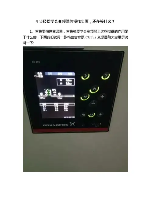
4步轻松学会变频器的操作步骤,还在等什么?1、首先要搞懂变频器,首先就要学会变频器上这些按键的作用是干什么的,下面我们就用一款格兰富水泵CU352变频器给大家展示说明一下:>表示下一步^ⅴ表示上下切换OK表示确认☜返回键+ -表示增加或减少2、首先我们想要想要三台水泵自动变为手动,我要按一下下一步。
就上面有一个向右的箭头。
然后就会出现另外一个画面,最下面有一个继续设置,通过上面的上下切换键到达我们想要的那一行,然后按下OK键就可以出现另外一个画面,就会出现四个框,想要自动变手动或者想要哪台水泵停机?都可以通过上下键切换到那一行。
然后按下OK键,勾选出你想要的结果。
如下面的图所示:3、如果你想要查看报警记录的话。
又要按一下下一步的箭头。
项目就会自动转换到下一个画面,里面有当前报警,还有一个报警记录,我们一般情况下就查看报警记录就可以了,这个也是通过上下键换到我们想要的地方,然后按下OK键。
里面就是我们想要查看的报警记录。
他记着里面有记载的时间,什么报警?或者是什么传感器出现了问题都会写的清清楚楚,如下面图所示:4、最后呢就是最主要的设置,我给大家先简单的介绍一下,因为它里面好多参数都是出厂设置好的,在没有特殊情况下一般不要去改变里面的参数,要想进入设置,它有一个密码保护,拿这款CU352来说,他的四位数密码就是1234。
再提醒一下,记住千万不要随意改变里面的参数。
如下图所示:好了,这些就是变频器的四步简单操作和按钮的一些功能。
小贴士:转发是最大的鼓励!谢谢您的支持!电工进阶全家桶:含有经典18本大全书,历年电工考试真题、电工必备实训仿真软件、电气自动化行业各类型技术手册!。
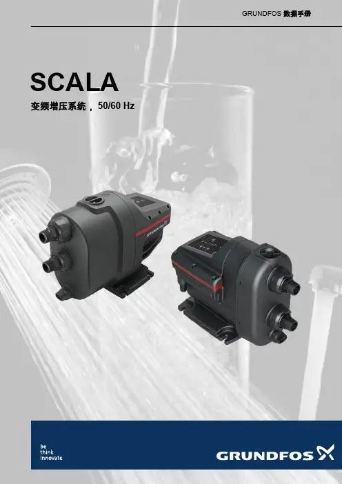
SCALA变频增压系统,50/60 HzGRUNDFOS 数据手册SCALA1.产品介绍 (3)目录特性和优点 (3)应用 (3)泵送液体 (3)产品范围 (4)性能范围 (4)2.选型指南 (5)3.安装和操作 (6)机械安装 (6)安装示范 (7)电气连接 (8)电机保护 (8)4.SCALA1 (9)产品范围 (9)电机 (9)SCALA1的特性和优点 (9)保护功能 (9)性能曲线 (10)技术数据 (12)认证和标志 (15)抽吸性能 (16)5.SCALA1双增压器系统 (17)特性和优点 (17)保护功能 (17)运行模式 (17)性能曲线 (18)技术数据 (19)6.SCALA2 (20)电机 (20)SCALA2的特性和优点 (20)保护功能 (20)性能曲线 (21)技术数据 (22)认证和标志 (24)抽吸性能 (24)7.配件 (25)SCALA双增压器系统配件包 (25)进水口过滤器 (26)8.产品编号 (27)SCALA1 (27)SCALA2 (29)9.格兰富产品中心 (30)2了各类应用的理想选择。
SCALA2格兰富SCALA2是一套完全集成的自吸式紧凑供水系统,适用于家庭增压应用。
SCALA2集成速度控制功能,可让水龙头维持绝佳的压力。
这意味着水泵的性能可以根据不断增长的需求进行调节。
1.1特性和优点SCALA 泵的优点:•安装简便。
•调试简便。
•操作简便。
特性SCALA1SCALA2自动启停√√自吸√√报警指示√√干转保护√√过度反复启停保护√√最长运行时间保护√√蓝牙通信√-双增压器√-外部输入√-可调节恒定压力-√集成变频器-√低噪音55 dB(A)47 dB(A)警告电击死亡或重度人身伤害‐请勿将本产品用于腐蚀性液体。
本产品只能用于泵送水。
警告有毒材料死亡或重度人身伤害‐请勿将本产品用于有毒液体。
本产品只能用于泵送水。
如果水中含有沙子、砾石或其他碎屑,则会有水泵堵塞及损坏的危险。
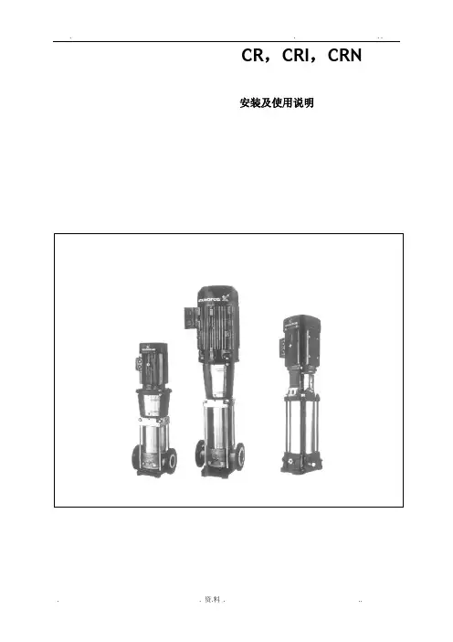
CR,CRI,CRN 安装及使用说明合格声明我们格兰富公司对本声明负全部责任, 本声明涉及的CR,CRI,CRN产品符合近似EEC 成员国法律的以下理事会准则:—机械制造(98/37/EEC)所用标准:EN292—电磁兼容性(89/336/EEC)所用标准:EN50 081-1及EN50 082-2—在一定电压范围内使用的电气设备的设计(73/23/EEC)所用标准:EN 60 335-1和EN 60 335-2-51.Bjerringbro /2001年2月1日Jan Strandgaard技术经理CR,CRI,CRN 安装及使用说明目录1. 处理 62. 型号规定 6 2.1 泵CR,CRI,CRN 1,3和5的型号规定 6 2.2 泵CR,CRI,CRN8和16的型号规定 6 2.3 泵CR,CRN 32,45,64和90的型号规定63. 应用 64. 技术参数7 4.1 环境温度7 4.2 液体温度7 4.3 轴封的最大允许工作压力和液体温度7 4.4 最小进口压力7 4.5 最大进口压力8 4.6 最小流量8 4.7 电气参数8 4.8 启动和停机频率8 4.9 尺寸与重量84.10 声压级85. 安装86. 电气连接96.1 变频器应用97. 启动98. 维护保养99. 防霜1010. 服务1010.1服务组件1011. 联轴器调节1012. 故障诊断表1113. 废物处理11开始安装之前,务必认真阅读本安装与使用说明书,安装和使用还要符合当地法规的要求。
1. 处理CR,CRI,CRN 1,3,5和CR,CRN 8,16泵的马达上提供了起吊孔,该孔绝不能用来起吊整台水泵。
当要吊起整台泵时,留意以下各项:●配有格兰富MG马达的CR,CRI,CRN 1,3,5和CR,CRN 8,16泵可以使用皮绳或者类似的绳索套在泵头上起吊。
●配有功率小于11kw(包括11kw)的格兰富MG马达的CR,CRN32,45,64和90泵,应使用泵头上的起吊孔起吊。
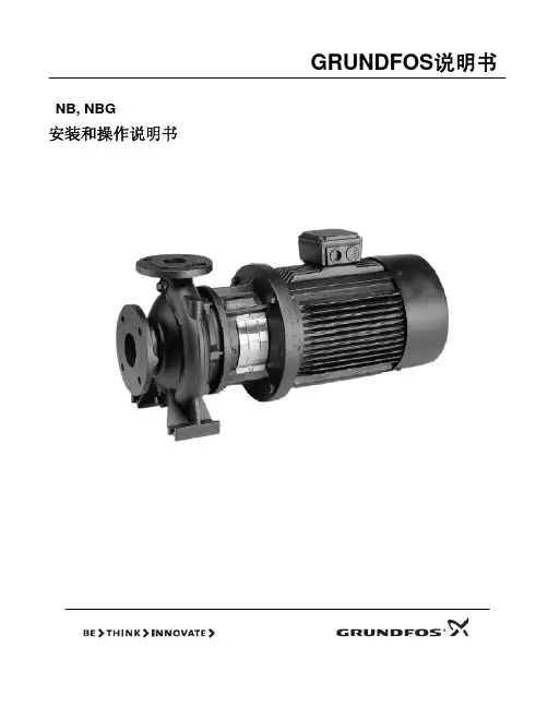
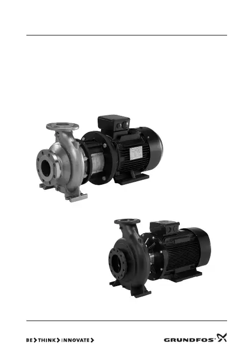
GRUNDFOS说明书NB, NBG安装和操作说明书目录页1. 一般信息 22. 交付和吊装 22.1 交付 22.2 吊装 23. 型号标示说明 33.1 NB 型 3 3.2 NBG 型 3 3.3 叶轮直径 5 3.4 泵的工作液体54. 技术数据 54.1 环境温度 54.2 液体温度 54.3 工作压力 5 4.4 最低入口压力 5 4.5 最高入口压力 54.6 最小流量 5 4.7 最大流量 54.8 电气数据 54.9 重量 54.10 噪音等级 5 4.11 泵的转速与材料尺寸的关系 55. 不含电机的泵 65.1 不带支脚的电机 65.2 带支脚的电机 86. 安装 10 6.1 安装前的准备 106.2 泵的位置 10 6.3 连接 106.4 基础 116.5 阻尼减振 11 6.5.1 软连接 12 6.5.2 阻尼减振器 12 6.6 直接连接管路 126.7 管路安装 126.8 旁路 12 6.9 测量仪器 137. 法兰受力与扭矩 138. 电气连接 14 8.1 电机保护 14 8.2 变频器的操作 14 9. 启动 149.1 一般信息 149.2 排气 14 9.3 检查转动方向 159.4 启动 15 9.5 起动/停车 1510. 维护 1510.1 泵 15 10.2 轴的机械密封 1510.3 电机 15 10.4 润滑 15 10.4.1 轴承润滑脂 15 11. 停泵期间的霜冻保护 15 12. 服务 1512.1 维修用成套备件 15 13. 最小入口压力的计算 1614. 故障检查表 1715. 处理 18在开始安装之前,应该仔细阅览设备的安装与工作说明书。
设备的安装与使用,也应该与本条例一致,并遵从良好的操作规范。
1. 一般信息泵的名称和型号标注在泵的铭牌上。
泵装有格兰富的MG 型或MMG 型电机。
如果泵所配的电机是 格兰富 以外的其他类型,请注意电机数据是否与本手册中所列数据有差异。
GRUNDFOS 数据手册Medium UPM泵UPMM, UPML, UPMXL, UPMXXL, SOLAR PMLEU系列1 x 230 V, 50/60 Hz目录2Medium UPM?1.概述3Medium UPM泵 - EU系列. . . . . . . . . . . . . . . . . . . . . . . . . . . . . . . . . . . . . . . . . . . . . . . . . . . . . . . . . . . . . . . . . . . . . . . 3应用 . . . . . . . . . . . . . . . . . . . . . . . . . . . . . . . . . . . . . . . . . . . . . . . . . . . . . . . . . . . . . . . . . . . . . . . . . . . . . . . . . . . . . . . . 3安全指导. . . . . . . . . . . . . . . . . . . . . . . . . . . . . . . . . . . . . . . . . . . . . . . . . . . . . . . . . . . . . . . . . . . . . . . . . . . . . . . . . . . . . 52.特点与优点6特点 . . . . . . . . . . . . . . . . . . . . . . . . . . . . . . . . . . . . . . . . . . . . . . . . . . . . . . . . . . . . . . . . . . . . . . . . . . . . . . . . . . . . . . . . 6优点 . . . . . . . . . . . . . . . . . . . . . . . . . . . . . . . . . . . . . . . . . . . . . . . . . . . . . . . . . . . . . . . . . . . . . . . . . . . . . . . . . . . . . . . . 6 ERP,生态设计规范. . . . . . . . . . . . . . . . . . . . . . . . . . . . . . . . . . . . . . . . . . . . . . . . . . . . . . . . . . . . . . . . . . . . . . . . . . . . 6标识 . . . . . . . . . . . . . . . . . . . . . . . . . . . . . . . . . . . . . . . . . . . . . . . . . . . . . . . . . . . . . . . . . . . . . . . . . . . . . . . . . . . . . . . . 73.性能概览84.产品范围95.控制模式和信号10控制原理. . . . . . . . . . . . . . . . . . . . . . . . . . . . . . . . . . . . . . . . . . . . . . . . . . . . . . . . . . . . . . . . . . . . . . . . . . . . . . . . . . . . 106.控制模式、用户界面和设置13供暖系统中的泵控制. . . . . . . . . . . . . . . . . . . . . . . . . . . . . . . . . . . . . . . . . . . . . . . . . . . . . . . . . . . . . . . . . . . . . . . . . . . 13控制模式说明. . . . . . . . . . . . . . . . . . . . . . . . . . . . . . . . . . . . . . . . . . . . . . . . . . . . . . . . . . . . . . . . . . . . . . . . . . . . . . . . 13用户界面. . . . . . . . . . . . . . . . . . . . . . . . . . . . . . . . . . . . . . . . . . . . . . . . . . . . . . . . . . . . . . . . . . . . . . . . . . . . . . . . . . . . 18 7.技术描述19爆炸图 . . . . . . . . . . . . . . . . . . . . . . . . . . . . . . . . . . . . . . . . . . . . . . . . . . . . . . . . . . . . . . . . . . . . . . . . . . . . . . . . . . . . . 19剖面观 . . . . . . . . . . . . . . . . . . . . . . . . . . . . . . . . . . . . . . . . . . . . . . . . . . . . . . . . . . . . . . . . . . . . . . . . . . . . . . . . . . . . . 20材料规格. . . . . . . . . . . . . . . . . . . . . . . . . . . . . . . . . . . . . . . . . . . . . . . . . . . . . . . . . . . . . . . . . . . . . . . . . . . . . . . . . . . . 20部件说明. . . . . . . . . . . . . . . . . . . . . . . . . . . . . . . . . . . . . . . . . . . . . . . . . . . . . . . . . . . . . . . . . . . . . . . . . . . . . . . . . . . . 21 8.安装尺寸23泵送液体. . . . . . . . . . . . . . . . . . . . . . . . . . . . . . . . . . . . . . . . . . . . . . . . . . . . . . . . . . . . . . . . . . . . . . . . . . . . . . . . . . . . 23机械安装. . . . . . . . . . . . . . . . . . . . . . . . . . . . . . . . . . . . . . . . . . . . . . . . . . . . . . . . . . . . . . . . . . . . . . . . . . . . . . . . . . . . 24电气安装. . . . . . . . . . . . . . . . . . . . . . . . . . . . . . . . . . . . . . . . . . . . . . . . . . . . . . . . . . . . . . . . . . . . . . . . . . . . . . . . . . . . 26 9.启动3110.维修3211.产品处置3412.性能曲线35曲线条件. . . . . . . . . . . . . . . . . . . . . . . . . . . . . . . . . . . . . . . . . . . . . . . . . . . . . . . . . . . . . . . . . . . . . . . . . . . . . . . . . . . . 3513.数据表3614.附件4515.批准和认证46EC产品合格声明书 . . . . . . . . . . . . . . . . . . . . . . . . . . . . . . . . . . . . . . . . . . . . . . . . . . . . . . . . . . . . . . . . . . . . . . . . . . . 46 VDE证书 . . . . . . . . . . . . . . . . . . . . . . . . . . . . . . . . . . . . . . . . . . . . . . . . . . . . . . . . . . . . . . . . . . . . . . . . . . . . . . . . . . . 47对某些不能使用的化学物质,格兰富提供产品化学符合声明. . . . . . . . . . . . . . . . . . . . . . . . . . . . . . . . . . . . . . . . . . . . 47 REACH法规(EC 1907/2006). . . . . . . . . . . . . . . . . . . . . . . . . . . . . . . . . . . . . . . . . . . . . . . . . . . . . . . . . . . . . . . . . . 47有关REACH、RoHS和其他相关化学品法规以及格兰富产品化学品合规性计划的客户信息. . . . . . . . . . . . . . . . . . . . 47 WEEE指令2012/19/EU. . . . . . . . . . . . . . . . . . . . . . . . . . . . . . . . . . . . . . . . . . . . . . . . . . . . . . . . . . . . . . . . . . . . . . . . 48 16.缩写493不同的管路可以安装不同版本的Medium UPM循环泵。
US Installation and operating instructionsShipment Inspection (2)Pre-Installation Checklist (2)Installation (3)Electrical (4)Start-Up (5)Operation (6)Failure to Operate (6)Warranty (7)CONTENTSGRUNDFOS INSTRUCTIONS UP Series circulatorsShipment InspectionExamine the components carefully to make sure no damage has occurred to the pump during shipment. Care should be taken to ensure the pump is NOT dropped or mishandled; dropping will damage the pump.Pre-Installation ChecklistBefore beginning installation procedures, the following checks should be made. They are all important for proper installation of the circulator pump.1. Uses: Model UP(S)15, 26, 43 and 50 series pumps are generally designed to circulate water from 32 deg F to 230 deg F up to a maximum pressure of 150 psi. Some models have temperature limitations which are shown in Table 2A below. If required, a 50% by volume solution of ethylene or propylene glycol and water can be used, however, a decrease in pump performance may result due to an increase in the viscosity of the solution. Check with manufacturer for information regarding suitability of pumping other fluids.Closed Systems: Model UP(S)15, 26, 43 and 50 series pumps with cast iron pump housings are designed to pump water compatible with their cast iron construction. They are recommended for use in closed hydronic systems.(i.e. airless, non-potable water).Open Systems: Model UP(S)15, 26, 43 and 50 series pumps with stainless steel or bronze pump housings are designed to pump water compatible with their construction and can be used in both open and closed systems. 2. Maximum Water Temperature:The maximumallowable water temperature is determined by the ambient or surrounding air temperature as shown in Table 2A.Table 2A – Maximum Water Temperature Ambient (°F) 104 120 140 160 175Water All UP* (°F) 230 220 210 190 175*Exceptions below:UPS15-35 165 140 - - -UP15-100F (°F)205 195 185 175 -UP26-120U (°F)205 195 185 175 -UP26-116 (°F)150 140 - - -23. Inlet Pressure Requirements The amount of pressure required at the inlet of the pump is a function of the temperature of the water as shown in Table 2B.In a pressurized system, the required inlet pressure is the minimum allowable system pressure.In a system open to the atmosphere, the required inlet pressure is the minimum distance the pump must be located below the lowest possible water level of the water source (tank, pool, etc.). InstallationPosition of terminal box: Proper installation of the pump will have the terminal box located to one side of the pumpIf the terminal box position needs to be changed, it is best to do so before installation. However, if the pump is already installed, ensure that the electrical supply is turned off and close the isolation valves before removing the Allen screws.To change terminal box position:1. Remove the four (4) Allen screws (4 or 5mm wrench) while supporting the stator (motor).2. Carefully separate the stator from the pump chamber and rotate it to the correct terminal box orientation.3. Replace the Allen screws and tighten diagonally and evenly (7 ft.-lb. torque).4. Check that the impeller turns freely. If the impeller does not turn easily, repeat the disassembly/ reassembly process.Fluid Temp 230° (110°C)190° (88°C)140° (60°C)Feet of Water 36 ft. (1.10m)9 ft (2.8m) 3 ft (0.9m)Inlet Pressure 15.6 psi 4.0 psi 1.3 psiTable 2B - Minimum Required Inlet Pressure3Pump Mounting: For Indoor UseArrows on the side or bottom of the pump chamber indicate direction of flow through the pump. GRUNDFOS circulators can be installed in both vertical and horizontal lines. The pump must be installed with the motor shaft positioned horizontally. Under no circumstances should the pump be installed with the shaft verticalIt is recommend that isolation valves be installed on each side of the pump. If possible, do not install elbows, branch tees, and similar fittings just before or after the pump. Provide support to the pump or adjacent plumbing to reduce thermal and mechanical stress on the pump.Installation Requirements1. Thoroughly clean and flush the system prior to pumpinstallation.2. Do not install the pump at the lowest point of the system wheredirt and sediment naturally collect.3. Install an air vent at the high point(s) of the system to removeaccumulated air.4. Ensure that water does not enter the terminal box during theinstallation process.5. (Open System) Install the pump in the supply line;the suction side of the pump should be flooded withwater. Ensure that the static head requirement fromTable 2B is achieved.6. (Closed System) Install a safety relief valve toprotect against temperature and pressure build-up.7. I f t h e r e a r e e x c e s s i v e s u s p e n d e d p a r t i c l e s i nthe water, it is recommended that a strainer and/or filterbe installed and cleaned regularly.8. DO NOT START THE PUMP UNTIL THE SYSTEM HAS BEENFILLED.CHECK VALVE REMOVAL:1. Use needle nose pliers to remove check valve from pumphousing. 2. Check to make sure no part of the valve remains in the pump housing. 3. Apply enclosed round "Check Valve Removed" label over the Check mark symbol located on the name plate of the pump.45Electrical All electrical work should be performed by a qualified electrician in accordance with the latest edition of the National Electrical Code, local codes and regulations.Warning: The safe operation of this pump requires that it be grounded in accordance with the National Electrical Code and local governing codes or regulations. The ground wires should be copper conductor of at least the size of the circuit conductor supplying power to the pump. Minimum ground wire size is 14 AWG. Connect the ground wire to the grounding point in the terminal box and then to an acceptable ground. Do not ground to a gas supply line.The proper operating voltage and other electrical information can be found on the nameplate attached to the top of the motor. Depending on pump model, the motor has either built-in, automatic resetting thermal protection or is impedance protected and in either case does not require additional external protection. The temperature of the windings will never exceed allowable limits, even if the rotor is locked.Wire sizes should be based on the ampacity (current carrying properties of a conductor) as required by the latest edition of the National Electrical Code or local regulations. Both the power and grounding wires must be suitable for at least 194°F (90°C).For all 115V and 230V models: Connect the white/white electrical leads from the circulator to the incoming power leads with wire nuts or other approved connectors. Attach incoming grounding wire to either of the green grounding screws.Ground WhiteGreenGrounding Screws CapacitorWiring diagram for all 115V and 230V single speed pumps.Figure 16Start-UpDo not use the pump to vent the system. Do not start the pump before filling the system. Never operate the pump dry. OperationGRUNDFOS domestic circulating pumps, installed properly and sized for correct performance, will operate quietly and efficiently and provide years of service. Under no circumstances should the pump be operated without water circulation or without the minimum required inlet pressure for prolonged periods of time. This could result in motor and pump damage.UPS model pumps are multispeed, and the speed can be changed by a speed selector switch located on the front of the terminal box. UP models are single speed.Failure to OperateWhen UPS 15-42 and UPS 26/43 pumps are first started, the shaft may rotate slowly until water has fully penetrated the bearings. If the pump does not run, the shaft can be rotated manually. To accomplish this, switch off the electrical supply, and close the isolation valves on each side of the pump. Remove the indicator plug in the middle of the nameplate. Insert a small flat blade screwdriver into the end of the shaft, and gently turn until the shaft moves freely. Replace and tighten the plug. Open the isolation valves and wait 2 to 3 minutes for the system pressure to equalize before starting the pump.NOTE: After a long shut down multi-speed pumps should be started on speed 3 and then adjusted to the regular setting. The UPS 15-42 has automatic function to assist in restart.*IMPORTANT NOTE*: For figure 1, the cap plug has not been installed. This pump is supplied with two wiring ports. To ensure safe operation of your installation, the enclosed cap plug MUST be inserted into the unused port.*UP(S) 15 capacitor wire position 4 & 8 *UP(S) 26/43/50capacitor wire position 2 & 4Wire the hot lead to terminal "L," neutral wire to terminal "N," and ground to the grounding terminal. For 230 volt pumps, the two hotLimited WarrantyUPS15, 26, 43 circulator pumps manufactured by GRUNDFOS PUMPS CORPORATION (GRUNDFOS) are warranted to the original user only to be free of defects in material and workmanship for a periodof 36 months from date of manufacture. GRUNDFOS' liability under this warranty shall be limited to repairing or replacing at GRUNDFOS' option, without charge, F.O.B. GRUNDFOS' factory or authorized service station, any UPS15, 26, 43 or UP15-42F circulator pump. GRUNDFOS will not be liable for any costs of removal, installation, transportation, or any other charges which may arise in connection with a warranty claim.All other UP and UPS small circulators manufactured by GRUNDFOS PUMPS CORPORATION (GRUNDFOS) are warranted to the original user only to be free of defects in material and workmanship for a periodof 24 months from date of installation, but not more than 30 months from date of manufacture. GRUNDFOS' liability under this warranty shall be limited to repairing or replacing at GRUNDFOS' option, without charge, F.O.B. GRUNDFOS' factory or authorized service station, any product of GRUNDFOS manufacture. GRUNDFOS will not be liable for any costs of removal, installation, transportation, or any other charges which may arise in connection with a warranty claim. Products which are sold but not manufactured by GRUNDFOS are subject to the warranty provided by the manufacturer of said products and not by GRUNDFOS' warranty.GRUNDFOS will not be liable for damage or wear to products caused by abnormal operating conditions, accident, abuse, misuse, unauthorized alteration or repair, or if the product was not installedin accordance with GRUNDFOS' printed installation and operation instructions.To obtain service under this warranty, the defective product must be returned to the distributor or dealer of GRUNDFOS products from which it was purchased together with proof of purchase and installation date, failure date, and supporting installation data. Unless otherwise provided, the distributor or dealer will contact the GRUNDFOS factoryor authorized service station for instructions. Any defective productto be returned to the factory or service station must be sent freight prepaid; documentation supporting the warranty claim and/or a Return Authorization must be included if so instructed.GRUNDFOS WILL NOT BE LIABLE FOR ANY INCIDENTAL OR CONSEQUENTIAL DAMAGES, LOSSES, OR EXPENSES ARISING FROM INSTALLATION, USE, OR ANY OTHER CAUSES. THERE ARE NO EXPRESS OR IMPLIED WARRANTIES, INCLUDING MERCHANTABILITY OR FITNESS FOR A PARTICULAR PURPOSE, WHICH EXTEND BEYOND THOSE WARRANTIES DESCRIBED OR REFERRED TO ABOVE.Some jurisdictions do not allow the exclusion or limitation of incidentalor consequential damages and some jurisdictions do not allow limitations on how long implied warranties may last. Therefore, the above limitations or exclusions may not apply to you. This warranty gives you specific legal rights and you may also have other rights which vary from jurisdiction to jurisdiction.7Grundfos Pumps Corporation 17100 W. 118th Terrace Olathe, Kansas 66061 Telephone: (913) 227-3400 Fax: (913) 227-3500Grundfos Canada, Inc.2941 Brighton Rd.Oakville, Ontario L6H 6C9Telephone: (905) 829-9533Fax: (905) 829-9512 Bombas Grundfos de Mexico,S.A. de C.V.Boulevard TLC #15,Parque Industrial Stiva AeropuertoC.P. 66600 Apodaca, N.L. MexicoTelephone: 52-81-8144-4000Fax: 52-81-8144-4010L-UP-TL-053 06.11 Repl. 06.07PRINTED IN USA。
GRUNDFOS数据手册CR, CRI, CRN50 Hz IEC立式多级泵1.产品概述 (3)典型应用 (3)泵送液体 (4)符合ErP指令 (4)2.性能范围 (5)3.产品范围 (6)4.应用 (8)5.特性和优点 (9)泵 (9)电机 (9)接线盒位置 (10)环境温度 (10)粘度 (10)6.结构 (11)CR 1s, 1, 3, 5, 10, 15, 20 (11)CRI 1s, 1, 3, 5, 10, 15, 20 (12)CRN 1s, 1, 3, 5, 10, 15, 20 (13)CR 32, 45, 64 (14)CRN 32, 45, 64 (15)CR 95, 125, 155, 185, 215, 255 (16)CRN 95, 125, 155, 185, 215, 255 (17)7.标识 (18)型号说明 (18)8.运行条件 (20)最大运行压力和最高液体温度 (20)轴封的运行范围 (22)最大入口压力 (23)9.选型 (24)泵的选择 (24)如何读懂曲线图 (28)性能曲线参考指南 (29)10.性能曲线与技术数据 (30)CR 1s (30)CRI, CRN 1s (32)CR 1 (34)CRI, CRN 1 (36)CR 3 (38)CRI, CRN 3 (40)CR 5 (42)CRI, CRN 5 (44)CR 10 (46)CRI, CRN 10 (48)CR 15 (50)CRI, CRN 15 (52)CR 20 (54)CRI, CRN 20 (56)CR 32 (58)CRN 32 (60)CR 45 (62)CRN 45 (64)CR 64 (66)CRN 64 (68)CR 95 (70)CRN 95 (72)CR 125 (74)CRN 125 (76)CR 155 (78)CRN 155 (80)CR 185 (82)CRN 185 (84)CR 215 (86)CRN 215 (88)CR 255 (90)CRN 255 (92)11.电机数据 (94)二极电机,用于CR,CRI,CRN,50 Hz (94)12.泵送液体列表 (95)13.配件 (97)管道连接 (97)LiqTec (107)传感器 (108)14.变型 (109)15.Grundfos Product Center (110)CR, CRI, CRN2目录1.产品概述本数据手册介绍格兰富CR、CRI 和CRN 泵。