螺纹插装阀的安装
- 格式:docx
- 大小:129.40 KB
- 文档页数:2
球阀直通螺纹安装方法球阀是一种常用的流体控制阀门,常用于管道系统中的开关控制。
球阀直通螺纹安装是一种常见的安装方式,下面将详细介绍球阀直通螺纹的安装方法。
1. 材料准备在进行球阀直通螺纹安装之前,需要准备以下材料:- 球阀:根据需要选择相应规格的球阀,确保与管道和介质的配套性。
- 管道:根据实际需要选择适合的管道材质和规格。
- 聚四氟乙烯密封带:用于密封螺纹连接处,避免漏气。
- 扳手:用于拧紧螺纹连接。
2. 球阀直通螺纹安装步骤步骤1:准备工作首先,确保工作区域干净整洁,并将所需材料和工具准备齐全。
步骤2:准备管道根据球阀的尺寸,选择相应规格的管道,并根据需要进行切割,确保管道两端平整,没有毛刺和污垢。
步骤3:处理球阀端口将球阀两端的保护帽取下,并使用扳手拧紧球阀底部的球体,以防止球体滑落。
如果球阀底部带有座圈,确保座圈垫片完好无损。
步骤4:涂抹密封带用手将聚四氟乙烯密封带缠绕在球阀螺纹部位,根据需要重复涂抹几层密封带。
步骤5:安装球阀将涂抹了密封带的球阀与管道螺纹连接部位对准,轻轻旋转球阀,确保螺纹连接均匀插入。
然后,使用扳手逆时针拧紧球阀与管道的螺纹连接。
步骤6:调整位置根据实际需要,调整球阀的位置,确保球阀的开关方向与管道的流动方向一致。
步骤7:测试安装完成后,打开管道供水,检查球阀的密封性能和开关情况。
检查球阀是否漏水、是否能顺畅开启和关闭等,确保球阀的正常运行。
注意事项在进行球阀直通螺纹安装时,需要注意以下事项:1. 选择适合管道和介质的球阀,确保其耐压性能和密封性能;2. 球阀的螺纹连接处应涂抹密封带,以确保螺纹连接的密封性;3. 在拧紧螺纹时,避免使用过大的力量,以免损坏球阀或导致螺纹连接失效;4. 安装完成后,务必检查球阀的开关性能和密封性能,确保其正常运行。
以上就是球阀直通螺纹安装的详细步骤和注意事项。
在进行安装之前,请确保对球阀安装方法和相关安全注意事项有充分了解,若有需要,可请专业人士进行安装。

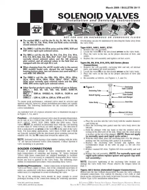
N O T F O R U S E O N H A Z A R D O U S O R C O R R O S I V E F L U I D SMarch 2009 / BULLETIN 30-11To ensure peak performance, solenoid valves must be selected and applied correctly; however, proper installation procedures are equally important. The following instructions list the essential points for correct installation.An exploded view of a typical solenoid valve is illustrated on page 4 in Figures 5, 5A, and 6.Position — All standard solenoid valves may be mounted horizontal, on its side or in a vertical line with the exception of the following: B33*, OB33*, XWG, XUP, XRN, XRM and XPO series. These valves MUST be installed in horizontal lines with the coil housing no more than 45° from vertical, see table on page 2. The direction of flow is indicated by an arrow or the word IN on the inlet of the valve body. For heat pump applications, valve types C(M)E and C(M)B are typically installed with the directional arrow pointing toward the outdoor coil. Or, the IN connection toward the indoor coil.NOTE: Solenoid valves having a type number starting with the letter “X” are Special Solenoid Valves (non-standard). Contact Sporlan if valve mounting is in question.SOLDER CONNECTIONSBecause of possible damage to valve components due to the high temperatures of soldering and brazing, “B” Series Solenoid Valves with brass connections are shipped handtight to facilitate disassembly. It is necessary to completely disassemble these valves before any heat is applied to the valve body. The following steps outline recommended procedures when installing these valves.Soldering Precautions — Solder connections on Sporlan Solenoid Valves are either copper or brass. Any of the commonly used types of solder are satisfactory with these materials. Regardless of the type of solder used, it is important to avoid overheating the valve.The tip of the soldering torch should be large enough to avoid prolonged heating of the connection during the soldering operation.Overheating can also be minimized by directing the flame away from the valve body.Type A3S1, S4S1, S6S1, S7S11. Remove the coil assembly.2. Locate the word IN or the directional arrow on the valve body.3. Place the valve in the line, in the proper direction of flow, and solder.4. Replace the coil assembly and tighten coil hex screw.Types B6, B9, B10, B14, B19, B25 Series (Brass Connections)1. Remove the coil assembly, enclosing tube and nut, all internal parts, and manual lift stem assembly.2. Locate the word IN or the directional arrow on the valve body.3. Place the valve in the line in the proper direction of flow and solder.4. Re-assemble as follows, see Figures 1, 5, and 5A:a. Place the seat disc into the valve body with the smaller diameter end facing up.b. Place the enclosing tube gasket onto the valve body above the threads.c. Hold the plunger with one hand so that the pointed end is resting in the pilot port of the disk. Make sure the small spring is in place on the top of the plunger. (NOTE: Does not apply to normally open and rapid cycle series.)d. With the other hand, place the enclosing tube over the plunger, making sure the enclosing tube gasket is in position.e. Replace the enclosing tube locknut and tighten. (See recommended torque in the table on page 2.) Do not over tighten.f. Replace manual lift stem. Tighten lift stem assembly and seal cap.g. Replace the coil assembly. (NOTE: For normally open and rapid cycle valves replace spacer and spacer cup with coil assembly.)NOTE: Excessive tightening of the enclosing tube locknut can damage the valve body bore. Please observe the torques listed on page 2.Types: All E Series (Extended Copper Connections)Brazed into the line without disassembly because the valve contains extended connections. Use caution by placing a wet cloth or chill block on the extensions at the body to prevent excessive overheating. Follow Type A3S1 installation instructions.(if required)n l l a t i o n a n d i c i n g I n s t r u c t i o n s© C opyright 2009 by S porlan V alVe D iViSion - p arker h annifin , W aShington , M iSSourib ulletin 30-11, M arCh 2009 S uperSeDeS b ulletin 30-11, J anuary 2007 anD all prior publiCationS .n The molded MKC-1 coil fits the E2, A3, E3, W3, S4, E5, B6, E6, S6, W6, S7, E35, R183, R184 and R246 series normally closed solenoid valves.n The OMKC-1 coil fits the OE35 series and the XWG, XUP and XXF series rapid cycle solenoid valves.n The MKC-2 coil fits the B9, E9, B10, E10, B14, E14, W14, B19, E19, W19, B25, E25, W25, B33*, E33*, E34*, E42 series normally closed solenoid valves and the 180 solenoid pilot control...and all solenoid valves in the field that are equipped with the old style KC-2 coil.n When changing from the old KC model coils to the current MKC molded model coils, discard the coil housing, coil housing bottom plate, two coil sleeves (not used with KC-1 coil) AND THE SPACER.n The OMKC-2 coil fits the OB9, OE9, OB10, OE10, OB14, OE14, OB19, OE19, OB25, OE25, OB33*, OE33*, OE34*, OE42 series normally open solenoid valves and the XRN, XRM, XPO series rapid cycle solenoid valves.n Other Sporlan products using a molded coil are as follows: MKC-1 — B5D, 8D, 12D, 16D, 10G, SORIT, SORIT-PI, SHGB(E)-8.MKC-2 — DDR-20, SHGB(E)-15, OLDR-15, OLDR-16 and OLDR-20.OMKC-2 — LDR-15, LDR-16, LDR-20, XTM and XTO.* E34, B33, and E33 are obsolete.* OE34, OB33, and OE33 are obsolete.Page 2 / BULLETIN 30-11RECOMMENDED TORQUE (ft.–lbs.)1Valves with mounting holes use a #8-32 screw torqued not more than 15 in.-lb. Note: Standard torque charts do not apply. 2Coil housing to be no more than 45° from the vertical. 3Coil housing must not be below horizontal. 4Do not over tighten the enclosing tube locknut. Damage to the enclosing tube assembly could result from over tightening.Note:For installation and service instructions on Three-Way Heat Reclaim Valves Type 8D, 12D & 16D, request Form SD-114.BULLETIN 30-11 / Page 3Wiring — Check the electrical specifications of the coil to be sure they correspond to the available electrical service.The 1/2” BX conduit connection or junction box on the coil may be rotated to any position by loosening the coil hexscrew. Solenoid valves with four-wire dual voltage coils have a wiring diagram decal, Figure 3, on the coil housing or bracket. This illustrates which wires to connect for either 120, 208 or 240 volt operation. Wiring and fusing (when used) must comply with prevailing local and national wiring codes and ordinances.Current Valves — A surge protector is each solenoid valve with a 115 volt DC coil. The surge protector is necessary to absorb the high counter-voltage generated when the circuit is broken, thereby protecting the electrical contacts of the thermostat. It should be wired as shown in Figure 4. SERVICING INSTRUCTIONSCAUTION — Dangerous hydraulic pressures may develop if a hand valve is installed in the liquid line ahead of the solenoid valve and the hand valve is closed while the solenoid valve is closed. This may cause extrusion of the teflon seat in the disc. Extrusion may cause the valve to fail to open, fail to close and/or have excessive seat leakage. Also the line between these two valves should be pumped down completely before disassembling the solenoid valve for service.NOTE: The optional manual lift stem is designed to prevent damage to the disc. If the stem is turned in too far, the threads become disengaged. These threads can be re-engaged by applying slight outward force while turning counterclockwise. A thread stop is provided to prevent the stem from backing all the way out of the assembly. Back the stem to the stop and replace the seal cap when service is complete.TYPICAL MALFUNCTIONSThere are only three possible malfunctions: 1. Coil burnout. 2. Failure to open. 3. Failure to close. Each is discussed.1. COIL BURNOUTCoil burnouts are extremely rare unless caused by one of the following: 1. I mproper electrical characteristics. 2. C ontinuous over-voltage, more than 10%.3. Under-voltage of more than 15%. This applies only if the operating conditions are such that the reduced MOPD causes stalling of the plunger, which results in excessive current draw.4. Incomplete magnetic circuit due to the omission of parts such as: coil housing, coil sleeves, coil spring, coil housing bottom plate or plunger on the KC model coil and coil yoke, coil backplate or plunger on the MKC molded model coils.5. M echanical interference with plunger movement which may be caused by a deformed enclosing tube.6. Voltage spike.7. Valve ambient exceeds 120°F.8. Fluid or gas temperatures greater than 240°F, while the valve ambient is 120°F.2. FAILURE TO OPEN (Normally Closed Types) 1. Coil burned out or an open circuit to coil connections. 2. I mproper electrical characteristics.3. I n pilot operated valves, dirt, scale or sludge may preventthe piston, disc or diaphragm from lifting. This could also be caused by a deformed body.4. High differential pressure that exceeds the MOPD rating of thevalve.5. Diameter reduction of synthetic seating material in pilot portbecause of high temperatures and/or pressures, or severe pulsations. Contact Sporlan Valve, Washington, MO.The problem of dirt can be avoided by installing a Sporlan Catch-AIl ® Filter-Drier upstream from the solenoid valve. The Catch-AII ® Filter-Drier will retain much smaller particles than a conventional strainer.Use a Sporlan strainer for water applications upstream of every industrial solenoid valve.3. FAILURE TO CLOSE1. Valve is oversized. Pilot operated valves may fail to close dueto low pressure drop.2. In pilot operated valves, dirt, scale or sludge may prevent thepiston, disc or diaphragm from closing. This could also be caused by a deformed body.3. Held open by the manual lift stem.4. In pilot operated valves only, a damaged pilot port may preventclosing.5. A floating disc due to severe discharge pulses, contact SporlanValve, Washington, MO.6. Have voltage feedback to the coil after the coil de-energizes.MISCELLANEOUS1. Liquid Hammer — Industrial solenoid valves, or other liquid line valves, may cause liquid hammer when installed on liquid lines with high liquid velocities. If this occurs, it can be minimized by the use of larger pipes, (i.e. lower velocities), or a standpipe installed in the piping near the solenoid valve inlet. Commercially available shock absorbers may also be used to reduce this noise. Recommended maximum velocity is approximately 300 fpm.2. AC Hum — This problem may be caused by a loose coil. A loose coil hex screw or coil locknut may cause this problem on the MKC molded model coils.Foreign material between the magnetic top plug and the plunger in t he Types A3, E3, W3, E5, B6, E6, W6, B9, E9, B10, E10, B14, E14, W14, B19, E19, W19, B25, E25, W25, E35 and E42 Series Solenoid valves may cause AC hum also.On water applications, deposits may accumulate in the valve which could cause AC hum. This may be eliminated by cleaning or flushing the valve.3. Leak Testing — Special care should be taken when leak testingvalves with synthetic gaskets. Gasket materials typically have a miniscule permeability. Leak rates of 0.5 oz. per year, depending on the valve size, is acceptable in most cases. Note the sensitivity of electronic leak detectors. Most have the capability of finding a leak smaller than 0.05 oz. per year. Double check small seal leaks with soap bubbles or a halide torch if possible. Do not over tighten the enclosing tube locknut. If a leak occurs, change the gasket and verify the metal surfaces have a clean smooth finish.c06-05c 06-05/v 021c 06-05/v 042t n e r r s e r e p t n e r r u C s e r e p m A t n e r r u C s e r e p m A -d l o H gn i -n I hs u r -d l o H gn i -n I hs u r -d l o H gn i 36.93.41.91.90.49.24.12.02.01.4.106.62.13.31.TRANSFORMER SELECTIONSurge ProtectorThermostatD. C. LinePage 4 / BULLETIN 30-11P rinted in the U.S. of A. 1009。
三个方法教您轻松安装阀门(一)引言:安装阀门是建筑和工程中的一个重要步骤,正确的安装可以确保阀门的正常运行和系统的有效运行。
本文将介绍三种轻松安装阀门的方法,帮助您完成这项任务。
概述:在开始安装阀门之前,需要明确安装位置和系统要求,准备好所需工具和材料。
然后,根据具体的安装方法,按照步骤进行操作。
我们将介绍以下三种方法:方法一:安装法兰连接阀门,方法二:安装螺纹连接阀门,方法三:安装焊接连接阀门。
每种方法都包含了详细的步骤和注意事项。
一、安装法兰连接阀门:1. 确定阀门的安装位置并测量,并选择合适的法兰尺寸。
2. 准备好安装所需材料和工具,如法兰、螺栓、螺母、密封垫片等。
3. 清洁法兰连接表面并在法兰上涂抹适当的密封剂。
4. 将阀门与法兰对齐,插入密封垫片,并使用螺栓和螺母紧固。
5. 检查安装情况,确保阀门与法兰紧密连接,并进行必要的调整。
二、安装螺纹连接阀门:1. 确定阀门的安装位置并测量,并选择适当的螺纹尺寸。
2. 准备好所需的材料和工具,如管道接头、螺纹密封胶等。
3. 清洁阀门和螺纹连接表面,并涂抹螺纹密封胶。
4. 将阀门插入螺纹连接口,并适当旋紧,确保连接牢固。
5. 检查连接情况,确保阀门与管道紧密连接,不出现泄漏。
三、安装焊接连接阀门:1. 确定阀门的安装位置并测量,并选择适当的焊接材料和方法。
2. 准备好所需的焊接材料和工具,如焊接电极、焊接机等。
3. 清洁阀门和连接管道的焊接表面,并进行必要的预热处理。
4. 进行焊接操作,确保焊接口牢固且密封。
5. 进行必要的测试和调整,确保阀门的正常运行和系统的完整性。
总结:通过以上介绍的三种方法,您可以根据安装位置和系统要求选择适当的安装方式。
在进行安装时,要仔细遵循每个步骤,并注意安全和质量。
正确安装阀门可以确保系统的正常运行和使用寿命,提高建筑和工程的效率。
希望本文对您在安装阀门时有所帮助。
手动插板阀安装说明手动插板阀是一种常用的阀门类型,广泛应用于各种领域。
本文将认真介绍手动插板阀的安装步骤及注意事项。
1. 材料准备在安装手动插板阀之前,需要准备以下材料:•手动插板阀本体•电动或手动操作装置•阀门法兰•法兰螺母和螺栓•包括法兰垫片在内的密封件2. 安装步骤2.1 准备工作在安装前,请确保以下工作已经完成:•确定阀门的安装位置,包括阀门的方向和高度;•清洁管道和法兰的内部;•调整法兰垫片和阀门,以便于紧密贴合;•检查操作装置是否安装正确。
2.2 安装阀门接下来,依照以下步骤安装手动插板阀:1.将阀门法兰放置于管道两端,并用螺栓紧固。
注意:为了确保阀门的精准定位,法兰必需安装在正确的位置上。
2.在法兰上放置阀门垫片和插板。
注意:垫片和插板必需完好无损,否则可能会导致泄漏。
3.将法兰和阀门紧密贴合,并用螺母和螺栓将其固定。
注意:在紧固法兰时,要均匀地加压,以避开变形或损坏。
2.3 安装操作装置假如需要安装电动或手动操作装置,请依照以下步骤操作:1.拆除阀门盖板;2.安装操作装置并用螺栓固定;3.连接阀门和操作装置。
3.注意事项在安装手动插板阀时,需要注意以下事项:1.阀门应当安装在垂直位置,以避开显现流体滞留的情况。
2.在安装过程中,不能将阀门用稍大或稍小的法兰来安装。
否则会导致紧固不良或泄漏的情况。
3.在使用之前,必需进行压力测试。
假如测试失败,则必需重新检查密封件及法兰连接,直到测试通过为止。
4.定期维护和清洁阀门,并检查各连接部位是否紧固。
如有其他疑问,请适时联系阀门厂家或相关专业人士。
4. 总结手动插板阀的安装是一个多而杂的流程,需要依照正确的步骤进行。
在安装阀门时,必需重视各连接部位的紧固度和完整性,以保证阀门的稳定运行。
希望本文对您在手动插板阀的安装方面有所帮忙。

螺纹阀门安装1、管道阀门安装(1)技术要求根据工作介质以及工作介质的参数(设计温度、设计压力、流量)选用阀门。
2、阀门的分类和用途(1)阀门的分类和用途主要用于截断或接通管路中的介质流。
一般用于低温、低压大管径上截止阀启闭件(阀瓣)由阀杆带动,沿阀座(密封面)轴线做升降运动。
密封性能比闸阀好。
流阻较大,高度大,主要用于截断或接通管路中的介质流。
一般对介质流向有要求球阀启闭件(球体)绕垂直于通路的轴线旋转。
启闭迅速主要用于截断或接通管路中的介质流。
常用于DN50mm以下管路蝶阀启闭件(蝶板)绕固定轴旋转。
启闭迅速,流阻较闸阀和球阀大,结构尺寸小主要用于截断或接通管路中的介质流。
常用于DN≥50mm的低压管道安全阀利用介质本身的力来排除额定数量的流体,以防止系统内的压力超过预定的安全值用于超压安全保护,排放多余介质,防止压力超过安全值1.止回阀启闭件(阀瓣)靠介质作用力自动阻止介质逆向流动用于防止管路中的介质倒减压阀通过启闭件的节流作用,将介质压力降低,并利用介质本身能量,使阀后压力自动满足预定要求,用于系统一次侧介质压力P1大于二次侧压力P2的场合2.恒温控制阀人为设定室温,通过温包感应环境温度产生自力式动作,无需外力即可调节热水流量以实现室温恒定与采暖散热器或其他采暖散热设备配合使用的一种专用阀门,用于房间温度控制调节阀阀体结构与截止阀相似,流量呈线性或等百分比特性,用于调节管路中介质的流量或压力。
3、材料要求及质量标准(1)阀门型号规格、材质及承压等应符合设计要求和施工规范规定。
(2)阀门铸造规矩,表面光洁,无毛刺、无裂纹。
开关灵活,关闭严密,填料密封完好无渗漏,首轮完整,无破损。
(3)阀门的产品合格证、检测报告应齐全、真实、有效。
(4)阀门的铭牌应符合现行国家标准《通用阀门标志》GB12220的规定。
4、作业条件(1)阀门安装前应核对其材质、型号、规格、及公称压力,并进行外观检查。
型号、规格、公称压力应正确,外观检查应合格(2)检查阀杆和间盘是否灵活,有无卡住和歪斜现象。
室外螺纹阀门安装施工方案1. 引言室外螺纹阀门广泛应用于城市给水、排水系统以及工业管道系统中,用于控制和调节介质的流动。
正确的安装施工方案是保证阀门正常运行和延长使用寿命的关键。
本文将介绍室外螺纹阀门的安装前准备工作、安装步骤以及注意事项。
2. 安装前准备工作2.1 阀门选择在开始安装之前,必须根据实际需求选择适当的室外螺纹阀门。
阀门的规格、材质和耐压等级应根据介质的性质和工程要求进行选择。
同时,还需要根据管道的尺寸确定阀门的连接螺纹规格。
2.2 安全措施在进行安装施工之前,应制定相应的安全措施。
安装人员必须佩戴合适的防护装备,如手套、护目镜和安全鞋等。
此外,应确保工作场所的清洁和整洁,防止事故的发生。
2.3 工具准备在开始安装之前,需要准备齐全的工具和器材,包括扳手、管子切割器、密封胶等。
确保工具的完好和合适,以便顺利进行安装工作。
3. 安装步骤3.1 管道准备首先,要对管道进行准备工作。
检查管道的尺寸和螺纹规格是否与阀门相匹配,必要时进行调整。
确保管道表面光滑、无杂质,并清洁管道螺纹,以便更好地连接阀门。
3.2 阀门安装将螺纹阀门与管道连接。
首先,将阀门的螺纹端部涂抹一层密封胶,然后将其插入管道螺纹中,顺时针旋紧。
使用扳手适当加强握紧力度,但不要过度用力,以免损坏阀门或导致漏水。
3.3 调试安装完成后,进行必要的调试工作。
打开阀门,检查阀门的开启和关闭是否顺畅,是否有异常噪音和泄漏现象。
如有异常,应及时采取措施进行修复或更换。
3.4 必要的标记和记录安装完成后,应对阀门进行标记和记录。
在阀门上标明其用途,并记录安装时间、施工人员、阀门编号等信息。
这有助于日后的维护和管理工作。
4. 注意事项4.1 防止阀门过度用力在安装过程中,应注意阀门的用力问题。
过度用力可能导致阀门损坏或螺纹变形,从而影响阀门的使用寿命。
4.2 防止漏水在安装阀门时,应确保螺纹紧密,防止漏水。
为了确保螺纹的紧密度,可以在螺纹部分涂抹一层密封胶。
克泰螺纹插装阀样本一、介绍克泰螺纹插装阀样本是一种用于控制流体的阀门装置。
它通过螺纹插装的设计,可以方便地安装在管道系统中,实现对流体的调节和控制。
本文将对克泰螺纹插装阀样本进行全面、详细、完整且深入的探讨。
二、结构和原理1. 结构克泰螺纹插装阀样本主要由阀体、阀芯、阀座、密封圈等组成。
阀体通常采用优质的铜材料制成,具有良好的耐腐蚀性和密封性能。
阀芯是控制流体通断的关键部件,通常由不锈钢制成,具有较高的强度和耐磨性。
阀座是阀芯的密封部位,通常采用橡胶或聚四氟乙烯等材料制成,具有良好的密封性能。
密封圈用于确保阀门的密封性能,通常采用橡胶材料制成。
2. 原理克泰螺纹插装阀样本的工作原理是通过旋转阀芯来控制流体的通断。
当阀芯旋转到与阀座完全贴合时,阀门处于关闭状态;当阀芯旋转到与阀座完全分离时,阀门处于开启状态。
通过控制阀芯的旋转角度,可以实现对流体的精确调节和控制。
三、特点和优势1. 特点•克泰螺纹插装阀样本具有结构简单、体积小、重量轻的特点,可以方便地安装在各种管道系统中。
•阀门的开关灵活、操作方便,可以快速实现对流体的通断。
•阀门的密封性能好,能够有效防止流体泄漏。
2. 优势•克泰螺纹插装阀样本采用优质材料制成,具有较高的耐腐蚀性和耐磨性,可以在恶劣的工作环境下长期稳定运行。
•阀门的设计精确,流体通过阀门时的阻力小,能够降低能耗和压力损失。
•克泰螺纹插装阀样本具有较高的工作压力和温度范围,适用于各种工业领域的流体控制需求。
四、应用领域克泰螺纹插装阀样本广泛应用于各个领域的流体控制系统中,包括但不限于以下几个方面: 1. 石油化工行业:用于石油、天然气等流体的调节和控制。
2. 电力行业:用于火力发电、核电等流体控制系统中。
3. 冶金行业:用于冶炼、炼钢等流体控制系统中。
4. 污水处理行业:用于污水处理厂的流体控制系统中。
5. 自动化设备行业:用于各类自动化设备的流体控制系统中。
五、安装和维护1. 安装安装克泰螺纹插装阀样本时,应按照以下步骤进行: 1. 清洗:将阀门和管道内的杂质清除干净,确保无阻塞物。
阀门装配时的螺栓紧固顺序和原则阀门在装配时螺栓紧固是十分重要的环节,不仅可以保证阀门的
正常运行,还能保证工作的安全性。
下面将介绍阀门装配时螺栓紧固
的顺序和原则。
第一,螺栓紧固的顺序。
在安装阀门时,螺栓紧固的顺序十分重要。
一般来说,螺栓的紧固需要进行交叉紧固,即从对角方向开始,
依次进行螺栓的加紧。
这样可以使螺栓受力均匀,防止出现单侧受力
过大,导致漏气或者脱落的情况。
另外,在紧固时需要遵循“交叉”、“环形”原则,即按照一定的顺序进行交叉紧固,同时可以进行环形
的调整,保证整体的紧固效果。
第二,螺栓紧固的原则。
在紧固螺栓时,需要遵循一些原则,以
保证阀门的稳固性和安全性。
首先是逐渐加压。
在紧固阀门螺栓时,
需要逐渐加压,不可一次过紧,以免造成局部受力过大,导致螺栓断
裂或者阀门损坏。
其次是均匀加紧。
在加紧螺栓时,需要保证力度均匀,不可使某些螺栓过紧,某些螺栓过松,这样可以保证整体受力均
匀。
最后是检查确认。
在紧固结束后,需要对所有螺栓进行检查确认,确保所有螺栓都已经紧固到位,并且没有松动的现象。
综上所述,阀门装配时螺栓紧固的顺序和原则十分重要。
我们需
要按照交叉紧固的原则进行螺栓的加紧,同时需要逐渐加压,均匀加紧,最后进行确认检查。
只有这样才能保证阀门的正常运行和工作的
安全性。
希望大家在实际操作中能够严格遵守这些原则,确保阀门装
配的顺利进行。

阀门螺纹连接步骤
嘿,小伙伴们!今天咱们来聊聊阀门螺纹连接的步骤。
这事儿说难不难,说简单也得注意不少小细节呢。
首先呢,得把要用的东西都准备好。
像阀门、带螺纹的管件之类的,可别到时候干着干着发现少个东西,那就麻烦啦!这一步看起来很简单,但建议不要跳过,避免后续出现问题。
我就有过这种情况,着急忙慌开始干,结果少了个小零件,又得重新找,耽误不少时间呢。
然后看看阀门和管件的螺纹部分。
这部分可得检查仔细咯!有没有损坏有没有脏东西呀之类的。
要是有脏东西,就清理一下。
我通常会在这个环节花多一些时间,确保做得更仔细。
你想啊,要是螺纹不干净或者有损坏,连接的时候可能就不顺畅,甚至还可能漏水啥的,那就糟心了,对吧?
接着呢,在螺纹上缠点密封材料。
这密封材料就像是给它们之间加了一道保险似的。
不过呢,缠多少合适呢?这个可以根据自己的经验来。
别缠太多,不然可能会挤到别的地方去;也别缠太少,起不到密封的作用。
这一点真的很重要,我通常会再检查一次,真的,确认无误是关键。
之后就可以开始连接啦。
把阀门和管件的螺纹慢慢对好,然后轻轻拧上。
这一步要特别小心哦!拧的时候要均匀用力,可不能歪着拧。
如果感觉有点紧,不要硬来,可以稍微调整一下方向再拧。
有时候我也会不小心拧歪一点,这时候就得退回来重新拧,不然容易把螺纹弄坏,那就得不偿失了。
最后再检查一遍整个连接的部分。
看看有没有哪里不对劲的,比如密封材料有没有被挤出来阀门和管件连接得是不是牢固呀之类的。
这一步千万不能省略哦!万一有啥问题,现在发现还来得及补救。
螺纹插装阀技术螺纹插装阀技术张海平2006-11目录目录前言1. 各类螺纹插装阀:构造,工作原理和性能2. 发展历史与现状3. 螺纹插装阀的应用4. 螺纹插装阀的局限性前言前言螺纹插装阀具有体积小、结构紧凑、应用灵活、使用方便、价格低等一系列优点,在欧美被广泛应用在农机、废物处理、起重机、拆卸设备、钻井、铲车、公路建设、消防车、林业机械、轮船、油井、矿井、扫路车、挖掘机、多用途车、金属切削、金属成型、机械手、铸造、成型、造纸、纺织、包装设备、动力单元、试验台等。
1. 各类螺纹插装阀:构造各类螺纹插装阀:构造,工作原理和性能,工作原理和性能,工作原理和性能插装阀(Cartridge Valve)从安装方式上可分为滑入式(Slip-in)和螺旋式(Screw-in)这两类。
滑入式即通常所称的二通插装阀或逻辑元件,它一般都还需要附加先导控制阀才能工作。
螺旋式即本文要述及的螺纹插装阀,它(装入安装孔后)一般都能独立完成一个或多个液压功能,如溢流阀、电磁方向阀、流量控制阀、平衡阀等。
以下摘取自一些国际市场上可见产品的使用说明书,供读者具体了解螺纹插装阀。
1.1单向阀单向阀Sterling 公司的D02B2:工作压力42MPa,最大流量80升/分,总长33.7mm,安装孔内部分长27.2mm。
1.2 溢流阀Sterling公司的A04R2M:工作压力0.5-35MPa,最大流量60升/分,总长123mm,安装孔内部分长46mm,直径22mm。
1.1.33电磁方向阀电磁方向阀::滑阀滑阀Hydraforce 公司的SV10-47C:工作压力21MPa,最大流量22升/分,总长188mm,孔内部分长62mm,直径22mm。
驱动线圈功率24W。
座阀座阀Sterling 公司的GS0408:工作压力35MPa,最大流量75升/分,总长94mm,孔内部分长33mm,直径22mm。
驱动线圈功率19W。
1.4 流量控制阀流量控制阀二通式:Hydraforce 公司的FR12-23,工作压力24MPa,最大流量77升/分,总长107mm,安装孔内部分长61mm,直径25mm。
精心整理1插装阀概述二通插装阀是插装阀基本组件(阀芯、阀套、弹簧和密封圈)插到特别设计加工的阀体内,配以盖板、先导阀组成的一种多功能的复合阀。
因每个插装阀基本组件有且只有两个油口,故被称为二通插装阀,早期又称为逻辑阀。
1.1二通插装阀的特点二通插装阀具有下列特点:流通能力大,压力损失小,适用于大流量液压系统;主阀芯行程短,动作灵敏,响应快,冲击小;抗油污能力强,对油液过滤精度无严格要求;结构简单,维修方便,故障少,寿命长;插件具有一阀多能的特性,便于组成各种液压回路,工作稳定可靠;插件具有通用化、标准化、系列化程度很高的零件,可以组成集成化系统。
1.2二通插装阀的组成二通插装阀由插装元件、控制盖板、先导控制元件和插装块体四部分组成。
图1是二通插装阀的典型结构。
图1二通插装阀的典型结构控制盖板用以固定插装件,安装先导控制阀,内装棱阀、溢流阀等。
控制盖板内有控制油通道,配有一个或多个阻尼螺塞。
通常盖板有五个控制油孔:X、Y、Z1、Z2和中心孔a(见图2)。
由于盖板是按通用性来设计的,具体运用到某个控制油路上有的孔可能被堵住不用。
为防止将盖板装错,盖板上的定位孔,起标定盖板方位的作用。
另外,拆卸盖板之前就必须看清、记牢盖板的安装方法。
图2盖板控制油孔先导控制元件称作先导阀,是小通径的电磁换向阀。
块体是嵌入插装元件,安装控制盖板和其它控制阀、沟通主油路与控制油路的基础阀体。
插装元件由阀芯、阀套、弹簧以及密封件组成(图3)。
每只插件有两个连接主油路的通口,阀芯的正面称为A口;阀芯环侧面的称作B口。
阀芯开启,A口和B口沟通;阀芯闭合,A口和B口之间中断。
因而插装阀的功能等同于2位2通阀。
故称二通插装阀,简称插装阀。
图3插装元件根据用途不同分为方向阀组件、压力阀组件和流量阀组件。
同一通径的三种组件安装尺寸相同,但阀芯的结构形式和阀套座直径不同。
三种组件均有两个主油口A 和B、一个控制口x,如图4所示。
a)方向阀组件b)压力阀组件c)流量阀组件1-阀套2-密封件3-阀芯4-弹簧5-盖板6-阻尼孔7-阀芯行程调节杆图3-89插装阀基本组件2插装阀主要组合与功能2.1插装方向控制阀插装阀可以组合成各式方向控制阀。
阀门的安装方法是什么(二)引言概述:阀门是工业生产和日常生活中常见的控制流体的装置,其安装方法直接影响到阀门的性能和使用效果。
本文将介绍阀门的安装方法,并分为5个大点进行详细阐述。
正文内容:一、准备工作1. 确定阀门的种类和型号。
2. 检查阀门和相关配件的完整性和质量。
3. 准备安装所需的工具和材料,如螺栓、垫片、密封胶等。
二、安装前的准备1. 清理安装位置,确保没有杂物和污垢。
2. 检查管道的尺寸和几何误差,确保与阀门相匹配。
3. 清理并检查阀门内部,确保通道畅通且没有异物。
三、安装阀门1. 将阀门放置在安装位置上,并根据需要进行固定。
2. 使用合适的工具拧紧阀门与管道之间的连接螺栓。
3. 根据需要,安装阀门的附件,如手轮、电动执行器等。
4. 检查阀门的开启、关闭和调节功能。
四、管道连接1. 根据阀门和管道的连接方式,选择合适的连接方法,如螺纹连接、法兰连接等。
2. 使用适当的密封材料,如垫片或密封胶,确保连接处密封可靠。
3. 根据需要,进行密封性能测试,如泄漏测试等。
五、调试和维护1. 在阀门安装完成后,进行阀门的调试工作,如检查阀门的开闭动作、调整流量等。
2. 根据阀门的使用情况,制定相应的维护计划,并按时进行维护工作,如加油、更换密封件等。
3. 定期检查阀门的密封性能和工作状态,并进行必要的维修和更换。
总结:本文介绍了阀门的安装方法,包括准备工作、安装前的准备、安装阀门、管道连接和调试维护等五个大点。
正确的阀门安装是确保阀门正常运行和延长使用寿命的关键,希望以上内容对阀门的安装有所帮助。
克泰螺纹插装阀样本
(原创实用版)
目录
1.克泰螺纹插装阀的概述
2.克泰螺纹插装阀的特点
3.克泰螺纹插装阀的应用领域
4.克泰螺纹插装阀的安装与维护
正文
一、克泰螺纹插装阀的概述
克泰螺纹插装阀是一种采用螺纹连接的插装式阀门,具有结构紧凑、操作简便、密封性能好等特点,广泛应用于各种流体控制系统中。
二、克泰螺纹插装阀的特点
1.结构紧凑:克泰螺纹插装阀采用螺纹连接,无需法兰,安装简便,可节省大量空间。
2.操作简便:克泰螺纹插装阀采用手轮或电动操作,操作力矩小,操作简便。
3.密封性能好:克泰螺纹插装阀采用优质的密封材料,具有良好的密封性能,可确保阀门在各种工况下的密封性能。
4.适用范围广:克泰螺纹插装阀适用于水、蒸汽、油、气体等各种流体介质的控制。
三、克泰螺纹插装阀的应用领域
克泰螺纹插装阀广泛应用于石油、化工、冶金、电力、建筑、食品、医药等行业的流体控制系统中。
四、克泰螺纹插装阀的安装与维护
1.安装:克泰螺纹插装阀在安装前,应先检查阀门的型号、规格是否符合设计要求,并检查阀门的密封面是否损坏。
安装时,应将阀门与管道的螺纹连接紧密,并加装密封胶垫,以确保密封性能。
2.维护:克泰螺纹插装阀在运行中,应定期检查阀门的密封性能,如有泄漏,应及时更换密封材料。
同时,应定期润滑阀门的操作部件,以保证阀门的操作灵活性。
螺纹阀门施工工艺施工准备1.材料准备1.首先得把螺纹阀门准备好,要检查阀门的型号、规格是不是和设计要求一致。
就像你要给特定的管道装阀门,不能把大的装在小管道上,也不能把该用在冷水管道的阀门装在热水管上,那肯定不行。
阀门的外观得没有损伤、变形,阀门的手轮、手柄这些部件得完整无缺,开关得灵活,关闭得严密。
这就好比你买个新玩具,得保证它是完好无损能正常玩的。
2.还有密封材料,像垫片这些,得选对材质。
如果是走水的管道,一般用橡胶垫片就挺好,但要是走有腐蚀性的液体,就得用耐腐的特殊垫片了。
而且垫片的尺寸要合适,不能太大也不能太小,太大了阀门拧不紧,太小了密封不严。
2.工具准备1.扳手是必不可少的,根据阀门的大小选择合适的扳手。
比如小口径的阀门,用小扳手就行,要是大口径的,就得用大的活动扳手或者专用扳手。
如果扳手不合适,要么拧不动阀门,要么把阀门拧坏了。
2.还得准备一些辅助工具,像螺丝刀(要是阀门有螺丝需要调整的时候用),还有生料带,这东西缠在螺纹上能起到密封作用。
施工工艺流程1.管道清理1.在安装螺纹阀门之前,要把管道的接口处清理干净。
如果管道里有杂物、铁锈什么的,就像你吃东西的时候有沙子在嘴里一样,会影响阀门的安装和使用。
用钢丝刷把管道螺纹部分的铁锈刷掉,再用干净的布把管道内外擦干净,保证管道接口光滑、干净。
2.阀门检查与清理1.把准备好的阀门再仔细检查一遍,看看阀门内部有没有杂物。
可以打开阀门,用压缩空气吹一下,把里面可能有的小石子、灰尘之类的东西吹出来。
对于阀门的螺纹部分,也要清理干净,不能有油污或者杂物,不然拧的时候会打滑,拧不紧。
3.缠绕生料带1.这一步可重要啦。
拿起生料带,从管道螺纹的一端开始,沿着螺纹方向缠绕。
要注意缠得均匀,不能有的地方厚有的地方薄。
一般缠个 3 - 5 圈就行,就像给螺纹穿上一层均匀的“保护衣”。
如果缠得太厚,阀门拧的时候阻力太大,还可能把生料带挤到阀门里面,影响阀门正常工作;缠得太少,密封就不好,容易漏水或者漏气。
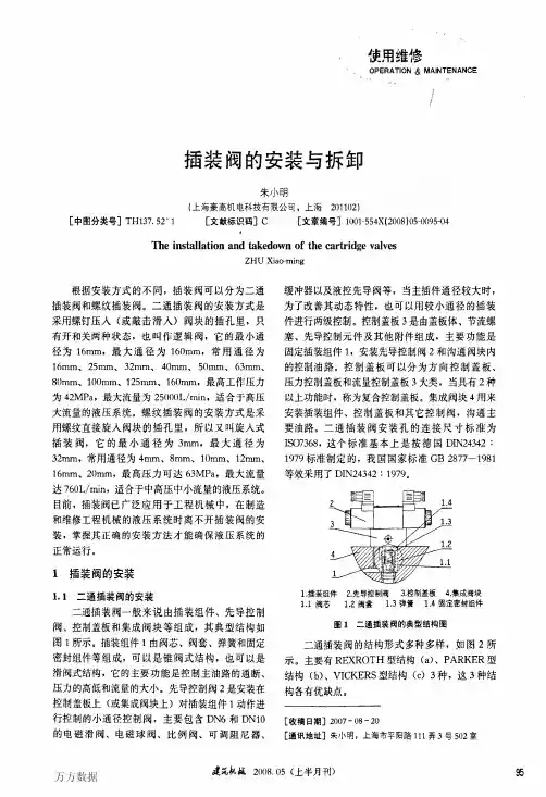
螺纹插装阀的安装
螺纹插装阀的安装方式是将螺绞直接旋入阀块的插孔里,安装拆卸简单快捷。
螺绞插装阀典型结构图如图1所示,由阀套、阀芯、阀体、密封件、控制部件(弹簧座、弹簧、调节螺杆、磁性体、电磁线圈、弹垫等)等组成。
螺纹插装阀有二通、三通、四通等型式;方向阀有单向阀、液控单向阀、梭阀、液动换向阀、手动换向阀、电磁滑阀、电磁球阀等;压力阀有溢流阀、减压阀、顺序阀、平衡阀、压差溢流阀、负载敏感阀等;流量阀有节流阀、调速阀、分流集流阀、优先阀等。
1阀套 2.阀芯 3.阀体 4.密封件 5.控制部件
图1 螺纹插装阀的典型结构图
安装螺纹插装阀之前应进行的工作与安装二通插装阀相同。
安装螺纹插装阀时,应先在插孔内和螺纹插装阀的阀套外圈(特别是密封圈处),涂上润滑脂或机油,再把螺纹插装阀放人插孔内,用力矩扳手(或开口扳手)旋人插孔内,常用通径螺纹插装阀所需的拧紧力矩见表1。
表1 常用通径螺纹插装阀所需的拧紧力矩表
安装螺纹插装阀时应该注意以下几点:
(1)安装螺纹插装阀应注意密封圈和挡圈不要在装配的过程中被切坏。
(2)由于螺纹插装阀组所装的螺纹插装阀较为密集,应该按一个方向依序进行安装。
(3)在安装电磁阀时,如安装空间不够,应该先将电磁铁卸下,待阀体安装完再把电磁铁装上。