螺纹插装阀技术
- 格式:pdf
- 大小:1.26 MB
- 文档页数:14

1插装阀概述二通插装阀是插装阀基本组件(阀芯、阀套、弹簧和密封圈)插到特别设计加工的阀体内,配以盖板、先导阀组成的一种多功能的复合阀。
因每个插装阀基本组件有且只有两个油口,故被称为二通插装阀,早期又称为逻辑阀。
1.1二通插装阀的特点二通插装阀具有下列特点:流通能力大,压力损失小,适用于大流量液压系统;主阀芯行程短,动作灵敏,响应快,冲击小;抗油污能力强,对油液过滤精度无严格要求;结构简单,维修方便,故障少,寿命长;插件具有一阀多能的特性,便于组成各种液压回路,工作稳定可靠;插件具有通用化、标准化、系列化程度很高的零件,可以组成集成化系统。
1.2二通插装阀的组成二通插装阀由插装元件、控制盖板、先导控制元件和插装块体四部分组成。
图1是二通插装阀的典型结构。
图1二通插装阀的典型结构控制盖板用以固定插装件,安装先导控制阀,内装棱阀、溢流阀等。
控制盖板内有控制油通道,配有一个或多个阻尼螺塞。
通常盖板有五个控制油孔:X、Y、Z1、Z2和中心孔a(见图2)。
由于盖板是按通用性来设计的,具体运用到某个控制油路上有的孔可能被堵住不用。
为防止将盖板装错,盖板上的定位孔,起标定盖板方位的作用。
另外,拆卸盖板之前就必须看清、记牢盖板的安装方法。
图2盖板控制油孔先导控制元件称作先导阀,是小通径的电磁换向阀。
块体是嵌入插装元件,安装控制盖板和其它控制阀、沟通主油路与控制油路的基础阀体。
插装元件由阀芯、阀套、弹簧以及密封件组成(图3)。
每只插件有两个连接主油路的通口,阀芯的正面称为A口;阀芯环侧面的称作B 口。
阀芯开启,A口和B口沟通;阀芯闭合,A口和B口之间中断。
因而插装阀的功能等同于2位2通阀。
故称二通插装阀,简称插装阀。
图3插装元件根据用途不同分为方向阀组件、压力阀组件和流量阀组件。
同一通径的三种组件安装尺寸相同,但阀芯的结构形式和阀套座直径不同。
三种组件均有两个主油口A和B、一个控制口x,如图4所示。
a)方向阀组件b)压力阀组件c)流量阀组件1-阀套2-密封件3-阀芯4-弹簧5-盖板6-阻尼孔7-阀芯行程调节杆图3-89插装阀基本组件2插装阀主要组合与功能2.1插装方向控制阀插装阀可以组合成各式方向控制阀。

专家简介张海平:德国蔡勒集团公司工学博士一、工作经历:目前,担任德国蔡勒集团公司技术顾问,山东泰丰液压设备公司技术顾问,上海理工大学客座教师,中国液压气动密封件工业协会第六届专家委员会委员。
1990年4月至2007年8月,供职德国蔡勒集团公司研发部,主管车载液压系统研发,设计,测试.1988年8月至1990年3月,在德国亚琛工大流体传动与控制研究所做博士后。
1985年3月至1988年2月,在上海交通大学机械系液压教研室攻博。
1982年至1985年2月,在上海工业大学机械系液压教研室任教师。
二、专业特长:液压系统设计,测试分析。
培训。
三、主要业绩:(如获得的奖励、撰写的论文、承担或参与重大项目的经历)有四项德国专利发明.1989年6月,作为洪堡学者获德国总统冯 魏茨泽克接见。
在泰丰公司参与组织的“大流量电液插装阀”获2009年度液气密行业优秀新产品一等奖。
论文:介绍一种新阀“软溢流阀”, <流体传动与控制>,2005-05 螺纹插装阀介绍之一溢流阀, <流体传动与控制>,2005-05,06螺纹插装阀介绍之二平衡阀, <流体传动与控制>,2006-03,05,06螺纹插装阀介绍之三电磁换向阀, <流体传动与控制>,2007-02,03螺纹插装阀技术,<流体传动与控制>,2004-2阀研发的趋势,<流体传动与控制>,2004-06?德国亚琛工大流体传动与控制教材简介,<液压气动与密封>,2003-06德国亚琛工大流技所的科研现状简介,<机电设备>, 2003 中国大学液压教材必须作重大改进, <液压气动与密封>,2009-06流体技术的过去和将来, <液压气动与密封>,2010-5测试是液压的灵魂, <液压气动与密封>,2010-6纠正一些关于稳态液动力的错误认识, <液压气动与密封>,2010-9差距和优势, <液压气动与密封>,2010-9四、希望参与哪些技术服务工作:技术培训讲座-实用液压技术基础-工程机械的液压速度控制原理-螺纹插装阀。
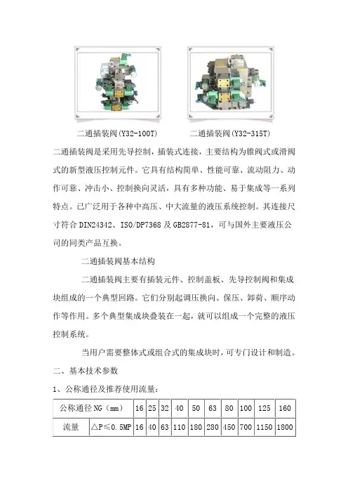
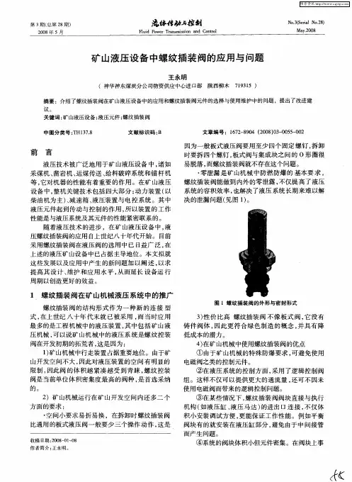
二通插装阀(Y32-100T) 二通插装阀(Y32-315T)二通插装阀是采用先导控制,插装式连接,主要结构为锥阀式或滑阀式的新型液压控制元件。
它具有结构简单、性能可靠、流动阻力、动作可靠、冲击小、控制换向灵活,具有多种功能、易于集成等一系列特点。
已广泛用于各种中高压、中大流量的液压系统控制。
其连接尺寸符合DIN24342、ISO/DP7368及GB2877-81,可与国外主要液压公司的同类产品互换。
二通插装阀基本结构二通插装阀主要有插装元件、控制盖板、先导控制阀和集成块组成的一个典型回路。
它们分别起调压换向、保压、卸荷、顺序动作等作用。
多个典型集成块叠装在一起,就可以组成一个完整的液压控制系统。
当用户需要整体式或组合式的集成块时,可专门设计和制造。
二、基本技术参数1、公称通径及推荐使用流量:公称通径NG(mm)16 25 32 40 50 63 80 100 125 160 流量△P≤0.5MP164063110180280450700115018002、工作压力:最高为31.5MPa;3、工作介质:本样本插装阀适用于矿物油,水乙二醇,油包水及水包油乳化液。
使用其它工作液时需特殊订货;4、工作介质温度范围:-20℃~80℃5、工作介质粘度范围:2.8~380cst(推荐13-54cst);6、工作介质的污染度:不低于ISO44020/16或NAS1638 10级(推荐滤油器过滤精度?0≥75);7、其它有关参数或超出以上范围时请向本公司查询。
二通插装阀安装连接尺寸(GB2877-81和DIN24342)通径16-63mm(点击详细说明)二通插装阀安装连接尺寸(GB2877-81和DIN24342)通径80-100mm (点击详细说明)二通插装阀安装连接尺寸(GB2877-81和DIN24342)通径16-63mm16 25 32 40 50 6365 85 102 125 140 180b2 62 85 102 125 140 18080 100 116 146 160 200 d1 H8 32 45 60 75 90 120 d2 H8 25 34 45 55 68 90d3 16 25 32 40 50 6316 25 32 40 50 6325 32 40 50 63 804 6 8 10 10 12d6 M8 M12 M16 M20 M20 M30 d7 H13 4 6 6 6 8 8 m1 ±0.246 58 70 85 100 125 m2 ±0.225 33 41 50 58 75 m3 ±0.225 33 41 50 58 75m4 ±0.223 29 3542.5 5062.5m5 ±0.210.516 17 23 30 38m6 32 40 48 60 68 85 t1 +0.1 43 58 70 87 100 130t2 +0.156 72 85 105 122 155t3 11 12 13 15 17 2034 44 52 64 72 9529. 5 40.548 5965.585.5t5 20 30 30 30 35 4020 25 35 45 45 65 t7 2 2.5 2.5 3 4 4 t8 2 2.5 2.5 3 3 4 t9 0.5 1.0 1.5 2.5 2.5 3 t10 10 10 10 10 10 1025 31 42 53 53 75U0.03 0.030.030.050.050.05W0.05 0.050.1 0.1 0.1 0.2注:1、先导阀和调节部分可以超出b规定尺寸2、工作口B可在(t1-t5)和(t1-t9)的深A:工作口 B:工作口X:控制口入口Y:控制口出口度范围内,围绕工作口A 的轴线任意布置,其轴线与孔d1相交可以不是90° 3、控制口深度和角度根据用途确定。
液压气动与密封/2009年第2期二通插装阀的拆卸与装配于良振王正磊杨红涛(山东泰丰液压设备有限公司,山东济宁272000)摘要:文章介绍了二通插装阀的主要结构,拆卸与装配的方法及注意事项,主要针对维修人员,同时也对设计和使用人员提供了有益的参考。
关键词:液压阀;二通插装阀;装配与拆卸工艺中图分类号:TH137.5文献标识码:A文章编号:1008-0813(2009)02-0072-03Assembling Process of Slip-in Cartridge ValvesYU Liang-zhen WANG Zheng-lei YANG Hong-tao(Shandong Taifeng Hydraulic Equipment Co.,Ltd,Jining272000,China)Abstract:The article introduce the master structure of two-way cartridge valves,as well as disassembly and assembly process.It could be useful for designeer and maintenance man.Key Words:hydraulic valves;two-way cartridge valves;assembling and disassembling process0引言插装阀是基于安装孔的模块化和可配组的集成式液压控制元件,符合今后液压控制的集成化将从安装面式向安装孔式过渡的总趋势,同传统的采用安装面式的滑阀控制技术有很大的区别。
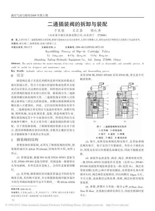
插装阀分为二通插装阀和螺纹插装阀两大类。
二通插装阀采用滑入式座阀主级和法兰固定式控制盖板,而螺纹插装阀则采用螺纹旋入并紧固的,因此,它们的结构和密封有所不同。
二通插装阀主要是用在大流量的系统中,如锻压机械、塑料机械、冶金轧钢设备、造船、铸造机械等行业。
MTechnical ReferenceHIC manifold design guidelines, tooling,torque specifications, port and cavity dimensionsT echnical Reference Section ContentsMReviewing CircuitAll designs begin with a sche-matic circuit design inspired by the application. Before the planning stage, review the design utilizing the following steps:• Match schematic symbols to model codes.• Note size and cavity of each valve and write it on schematic.• Note port numbers of the valves and write them on schematic.• Note manifold port types and sizes specified by customer.• Note pressure, flow and material of manifold block (steel or aluminum).Circuit questions should be answered by the customer before beginning a design. It is also recommended that schematic hydraulic regions or networks be color coded using color pens. Regions or net-works may be broken down in individual colors (pressure, tank, pilot, etc.) but it may be easier to design if regions are broken down into sub-regions such as pressure from port one of a solenoid valve to port two of a relief valve. Colored layers may be assigned later to match schematic circuit coloring.Initial DesignOnce the circuit is fully under-stood, it is advisable to lay the design out by hand first. Things to consider while plan-ning the design are:• Block size is often specified by customer.• Specify an overallenvelope size, in addition to the specified block size. Overall envelope size includes block size and any valves or fittings protruding from the manifold block.• Restrictions specified for a mounting surface of the manifold block. Valves and ports may be restrictedfrom a particular surface.• Specify mounting holes, threaded holes and thru holes (if necessary).• Arrange valves in a logical manner. Valves and ports in the same regions should be located in close proximity to each other.• Eliminate as many turns in the regions as possible to reduce the number of cross drill holes or construction lines. This helps keep pressure drops ( D P) andmanufacturing costs down.Material SizesTo obtain an optimal cost man-ifold it is desirable to select a standard material size for the manifold, compare the block size with the standard mate-rial size table. See Standard Material Sizes (page M-5). If a standard size is not available, a cut plate may be used. Hydraulic SchematicIf a schematic is desired on the assembly, it may be cre-ated from existing symbols. As an alternative, the entire circuit may be created outside of an assembly and imported as a symbol (block). All of the Vickers screw-in cartridge valves have schematic sym-bols which can be found in the SICV Cartridge Valve Library of Symbols CD, used in conjunc-tion with AutoCad software. Schematic symbols not found in the library may be created on an “as needed” basis.Accurate DesignAll dimensions on CAD design must be accurate and to scale in order to be utilized by CAM software in conjunction with CNC machine tools. Manually or interactively modifieddimension cannot be tolerated.Example:Note: Failure to ensure thatCAD dimensions are accurate and to scale may result in improper machinery by CNC Machine Tools.Datum PointThe datum point or origin point (0,0,0) on machining drawings is the upper left corner when facing the front view.Assembly Dimensioning Dimension all ports, mount-ing holes and overall envelope size.External ClearancesAllow enough room for clear-ance around solenoid coils, handknobs, levers and wrench clearance for fittings. If 90° elbow fittings are to be used, some may be required to swing a full 360 arc.Assembly NotesNotes are added for standard or special assembly, handling, or shipping instructions, as well as special stampings.Port T ableInclude a port table with names and sizes of all ports.Standard T oolingIn order to obtain fastturnaround on designs, limit the tooling used to that listed in the standard tooling table. See Preferred Tooling for Machining Manifolds (page M-6).General Guidelines forHydraulic Integrated Circuits (HIC)professional in the design of manifold blocks and related hydraulic systems. It is the designer’s responsibility to verify the adequacy of thedesign through approporate verifications, review and test-ing of the final design.Always “square up” the raw block before machining the cavities, ports and holes. This is to eliminate any potential “drill walk” which leads to scrapped manifolds. When squaring up a block, remove approximately 0.015” of material from each face for Aluminum blocks and 0.030” of material from each face for steel blocks. This is done to ensure that all six faces are parallel or perpendicular. Finished machining shouldreflect the squared up dimen-sions. See Standard Material Sizes (Table 1).Example: 4.0” x 5.0” x 6.0” (101.6 mm x 127 mm x 152.4 mm) block will be dimen-sioned to 3.97” x 4.97” x 5.97” (100.8 mm x 126.2 mm x 151.6 mm)Creation of MachiningT able Create a machining operation table or bore chart. Machining depths are given from the sur-face of the block. List all drill depths, mills, taps and form tools in the machining table. Call out drill depths at the shoulder depth of the drill, not to the drill point depth.All machining depths are to the corner of the full diameter as opposed to the drill point. All depths are measured from the face plane (surface) of a manifold block.Avoid any drill depths greater than 25 diameters.Additional line lengths may result in increasing pressure drops.Machining NotesMachining notes are to beadded for standard or special machining, handling and ship-ping instructions.DrillingsDrillings that go completely through a cavity port area should be on the center axis of the cavity wherever possi-ble; see Figure (a). Otherwise it should intersect the cavity tangent to the outside diam-eter of the bore it connects with; see Figure (b).Note: Breaking into a cavity at some point in between these recommended areas will lead to drill walk and can result in a high scrap rate, as well as premature drill breakage.All SAE ports and cavities have spotface depths of .031” (.8 mm) unless otherwise speci-fied. BSPP ports have spotface depths of .060” (1.5 mm) unless otherwise specified.CounterboresIn counterbore cases, the actu-al cavity spotface is located at the depth of the counterbore. When counterbore depths are greater than 0.125”, the follow-ing diameters should be used:Use of Expander Plugs and Zero Leak Gold SAE O-Ring PlugsOn small HIC packages, expander plugs can be used to block off construction drill-ing at the surface of a face. Larger than a 12mm expander plug are not recommended in aluminum. Any construction drillings larger than 0.4” (10 mm) are plugged with zero leak gold SAE O-Ring plugs (internal hex type). The machin-ing callout for these plugs can be either the industry standard SAE straight thread O-ring boss port configuration or the straight thread O-ring boss short port configuration. Refer to Port Dimensions (page M-9 and M-10).Surface T reatmentsAny manifold face that calls for a surface mounted (gas-ket mounted) valve such as a DG4V type directional control valve, or a pump or motor interface, should have a mini-mum roughness callout of 63 microinches (.0016mm) and a flatness callout of .002”(.05mm). See examples below.To prevent corrosion, steel manifolds are oil dipped or coated with rust protec-tive fluid, unless otherwise specified. To prevent oxidation, aluminum manifold blocks are gold anodize, unless oth-erwise specified. Aluminum manifolds where the internally grounded coil is used should not be anodized. Prototypes are supplied without surface treatment.Datum Point Example in orthographic third angle projection:General Guidelines forHydraulic Integrated Circuits (HIC)MWall ThicknessFor pressures up to 3000 psi (210 bar), aluminum may be used, for pressures above 3000 PSI (210 bar). Dura-Bar cast iron manifold material is recommended.Larger cavities or bores require a greater wall thick-ness.The table below shows recommended minimum wall thicknesses for Aluminum and Dura-Bar.general guidelines will notguarantee the manifold will survive any finite number of cycles. The only way to properly assure a specified life is to run a thorough testing of both burst and endurance in the actual application circuit.T able 1Standard Material SizesGeneral Guidelines forHydraulic Integrated Circuits (HIC)Creating Bill of Material – BOMDevelop a BOM that includes quantity, model codes, part numbers and descriptions of the HIC. Model codes of some valves require pressure settings. A machining opera-tion table or bore chart should be created. All plugs, orifice plugs, disks, check valves, pistons, and any other part should be included in the BOM.2 x 2 2 x3 2 x4 2 x5 2 x 62.5 x 2.5 2.5 x 3 2.5 x3.5 2.5 x 42.5 x 4.5 3 x 33 x3.53 x 43 x4.53 x 53.5 x 3.53.5 x 43.5 x 4.54 x 44 x 4.54 x 54 x 64.5 x 4.55 x 55 x 65.5 x 5.56 x 6lead to manifold failure.Preferred T ooling for Machiningof Custom ManifoldsFlat Bottom Reamer Reamer Slot BallPreferred T ooling for Machining Custom ManifoldsSense Check Took SC-4-2-75SC-4-2-88Counter Sink2" x 902" x 5"1/4" x 90Drill1/4" x 90Center Drill#5Press Tap#6-32 X#10-24 X1/4"-20 X1/4"-20 5/16"-18 5/16"-24 3/8"-16 3/8"-24 7/16"-14 7/16"-20 1/2"-13 1/2"-20 9/16"-185/8"-115/8"-183/4"-167/8"-141"-141-1/16"-121-3/16"-121-5/16"-121-5/8"-121-7/8"-121/8"-28 BSPP1/4"-19 BSPP3/8"-19 BSPP1/2"-14 BSPP3/4"-14 BSPP1"-11 BSPP1/16"-27 NPTF1/8"-27 NPTF1/4"-18 NPTF3/8"-14 NPTF1/2"-14 NPTF3/4"-14 NPTF1"-11 1/2 NPTFM10 x 1.5 MetricM10 x 1.25 MetricTap Pulley Tap1/4" - 205/16" - 247/16" - 209/16" - 183/4" - 16MT orque Specifications For Cartridge Valves and FittingsSAE and BSPP PortsSpotfaceMheighta Diameter U shall be concentric with thread pitch diameter within 0.0005 in. (0.13mm) FIR, and shall be free from longitudinal and spiral tool marks. Annular tool marks up to 100 mu in. max. are allowedb If face of boss is on a machined surface, dim. Y and S need not applyc Tap drill depths given require use of bottoming taps to produce the specified full thread lengths. Where standard taps are used, the tap drill depths must be increased accordingly.d Nominal tubing O.D. is shown for the standard inch sizes and the conversion to equivalent to mm sizes. Figures are for reference only, as any boss can be used for a tubing size, depending upon other design criteriaShort SAE portsPort DimensionsShort Port – Straight Thread O–Ring Boss – SP–**Note : To be used for SAE plugged construction holes only. Not intended to be used for external porting with standard fittings.Roughing T oolsRoughers are basically step drills which leave .030” per cutting diameter and .015” above all radii for the finish-ing reamer, with an additional .015” depth in the cavity bot-tom as clearance. The rough-ing tool is necessary to prepare the cavity for the fin-ishing reamer, which has not been designed for the primary forming or bottom cutting.Cavity For Material Model Code Part Number 2–WayC-4-2 Aluminum / Steel RT-4-2-AS-8306 02-173997C–8–2 Aluminum / Steel RT1–8–2–AS–8028 02–165580C–10–2 Aluminum RT–10–2–A–8030 889509C–10–2 Steel RT–10–2–S–8035 889510C–12–2 Aluminum / Steel RT–12–2–AS–8213 02–160625C–16–2 Aluminum RT–16–2–A–8031 889515C–16–2 Steel RT–16–2–S–8036 889516C–20–2 Aluminum RT–20–2–A–8032 565822C–20–2 Steel RT–20–2–S–8037 8895193–WayC-4-3 Aluminum / Steel RT-4-3-AS-8304 02-173271C–8–3 Aluminum / Steel RT1–8–3–AS–8291 02–162384C–10–3 Aluminum RT–10–3–A–8038 889511C–10–3 Steel RT–10–3–S–8043 889512C–12–3 Aluminum / Steel RT–12–3–AS–8217 02–153261C–16–3 Aluminum RT–16–3–A–8039 565825C–16–3 Steel RT–16–3–S–8044 889517C–20–3 Aluminum RT–20–3–A–8041 02–165581C–20–3 Steel RT–20–3–S–8046 5667063–Way ShortC–10–3S Aluminum RT–10–3S–A–8099 565824C–10–3S Steel RT–10–3S–S–8209 566703C–12–3S Aluminum / Steel RT–12–3S–AS–8220 02–113178C–16–3S Aluminum RT–16–3S–A–8040 02–165582C–16–3S Steel RT–16–3S–S–8045 566704C–20–3S Aluminum RT–20–3S–A–8042 889520C–20–3S Steel RT–20–3S–S–8047 5667054–WayC–8–4 Aluminum / Steel RT–8–4–AS–8292 02–172803C–10–4 Aluminum RT–10–4–A–8072 889513C–10–4 Steel RT–10–4–S–8073 889514C–12–4 Aluminum RT–12–4–A–8313 02-176377C–16–4 Aluminum RT–16–4–A–8074 889518C–16–4 Steel RT–16–4–S–8075 565828C–20–4 Aluminum RT–20–4–A–8076 565829C–20–4 Steel RT–20–4–S–8077 5667075–Way ShortC–12–5S Aluminum RT–12–5–A–8350 02-187301C–12–5S Steel RT–12–5–S–8358 02-187309C–16–5S Aluminum RT–16–5–A–8352 02-187303C–16–5S Steel RT–16–5–S–8360 02-187311C–20–5S Aluminum RT–20–5–A–8354 02-187305C–20–5S Steel RT–20–5–S–8356 02-187307Cavity For Material Model Code Part Number 2–WayC–4–2 Aluminum FT–4–2–A–8297 02–182339C–8–2 Aluminum / Steel FT1–8–2–AS–8070 02–112933C–10–2 Aluminum / Steel FT–10–2–AS–8048 566235C–12–2 Aluminum / Steel FT–12–2–AS–8214 02–162162C–16–2 Aluminum / Steel FT–16–2–AS–8078 565832C–20–2 Aluminum / Steel FT–20–2–AS–8079 5658333–WayC–4–3 Aluminum FT–4–3–A–8275 02–172006C–8–3 Aluminum / Steel FT–8–3–AS–8295 02–171292C–10–3 Aluminum / Steel FT–10–3–AS–8050 565834C–12–3 Aluminum / Steel FT–12–3–AS–8244 02–163001C–16–3 Aluminum / Steel FT–16–3–AS–8080 565836C–20–3 Aluminum / Steel FT–20–3–AS–8082 8893583–Way ShortC–10–3S Aluminum / Steel FT–10–3S–AS–8210 566708C–12–3S Aluminum / Steel FT–12–3S–AS–8242 02–162998C–16–3S Aluminum / Steel FT–16–3S–AS–8081 889356C–20–3S Aluminum / Steel FT–20–3S–AS–8083 8893594–WayC–8–4 Aluminum / Steel FT–8–4–AS–8296 02–171291C–10–4 Aluminum / Steel FT–10–4–AS–8052 565838C–12–4 Aluminum / Steel FT–12–4–AS–8312 02-175596C–16–4 Aluminum / Steel FT–16–4–AS–8084 566571C–20–4 Aluminum / Steel FT–20–4–AS–8085 889360.5–Way ShortC–12–5S Aluminum FT–12–5–A–8351 02-187302C–12–5S Steel FT–12–5–S–8359 02-187310C–16–5S Aluminum FT–16–5–A–8353 02-187304C–16–5S Steel FT–16–5–S–8361 02-187312C–20–5S Aluminum FT–20–5–A–8355 02-187306C–20–5S Steel FT–20–5–S–8357 02-187308Finishing Form T oolsSpeed & Feed for Aluminum 6061–T6 (T651) This information is recommended as a good starting point. Speeds and/ or feeds may be increased or decreased depending on actual machining conditions.Note: Finish form tools may require 1/2 to 1 1/2 second dwell to obtain necessary finish.Finishing T oolsThese finishing tools have been designed as preci-sion reamers for finishing operations only. They are not intended for primary forming or bottom cutting operations. Vickers recommends that a finishing tool only be used in a properly roughed hole. Failure to conform to this practicewill produce unsatisfactory size and finishes and possibly break the tool.MC–**–2(P)Dimensionsmm (inch)Cavity bores can be machined accurately in aluminum or steel. The necessary UNF , or UN threads may be machined using standard small tools, possibly already in yourmachine shop or from a local tool supplier.Either you, our customer, or Eaton can design and manufacture customized manifolds or housings dedicated to indi-vidual applications. We call the resulting valve packages Hydraulic Integrated Circuits (HIC). Cartridges selected for your application can be accom-modated in one or more HICs, according to your require-ments.WARNING For EPV-10 &CV16-10, thecavity should bemachined to the 14,29 (0.562) max diameter (dimension X) and to the maximum depth of 36,0 (1.417) (dimension J)Dimensions mm (inch)Cavity bores can be machinedaccurately in aluminum orsteel. The necessary UNF, orUN threads may be machinedusing standard small tools,possibly already in yourmachine shop or from a localtool supplier.Either you, our customer, orEaton can design and manufacture customized manifoldsor housings dedicated to indi-vidual applications. We callthe resulting valve packagesHydraulic Integrated Circuits(HIC). Cartridges selected foryour application can be accom-modated in one or more HICs,according to your require-ments.WARNINGFor EPV-10 &CV16-10, thecavity should bemachined to the 14,29 (0.562)max diameter (dimension X)and to the maximum depth of36,0 (1.417) (dimension J)C-**-2 CavityDimensions(0.0625) Runless otherwise specifiedunless otherwise specified2-way cavity with undercut (u)MC-**-3 Cavity Dimensionsunless otherwise specified unless otherwise specifiedDimensionsmm (inch)MDimensionsmm (inch)MC-**-5SCavityDimensionsDimensionsmm (inch)Cartridge Cavities IndexMOur cavities have beendesigned to achieve standard-ization based on each thread size to reduce the amount of tooling required to cover the valve range. All new designs of cartridge are made to fit the ISO recommendations forstandard cavities. The diagram below shows the sequence of tooling using tools specified in the following pages. Note: a pilot drill may be required before the form drill.Great care must be taken to ensure that the tools are inserted along the same machining axis to maintain correct concentricities, hence bodies should not be moved between operations.Operation 1Form Drill Operation 2Form Reamer Operation 3Plug T apIndexCavity A877Cavity T ools Form Drill A1161Form Reamer A1162Plug Tap 1 5/16-12 UNFCavity A879 Cavity T ools Form Drill A1040Form Reamer A1041Plug Tap3/4-16 UNFCavity A878 Cavity T ools Form Drill A885Form Reamer A1173Plug Tap7/8-14 UNFCavity A880Cavity T ools Form Drill A1302Form Reamer A1303Plug Tap1-14 UNS45.0028.00Ø26.00ØMCavity A881Cavity T ools Form Drill A1183Form Reamer A1036Plug Tap1 -14 UNFCavity A1126 Cavity T ools Form Drill AT422Form Reamer AT488Plug Tap1 5/8-12 UNFCavity A893Cavity T ools Form Drill A894Form Reamer AT491Plug Tap7/8-14 UNFCavity A3145Cavity T oolsForm Drill A3226 Form Reamer A3227 Plug Tap 1 5/16-12 UNCavity A3531Cavity T oolsForm Drill A3538 Form Reamer A3539 Plug Tap 3/4-16 UNF Cavity A3146Cavity T oolsForm Drill A3315 Form Reamer A3316 Plug Tap 1 1/8-12 UNFCavity A5302Cavity T oolsForm Drill A5668 Form Reamer A5669 Plug Tap 7/8-14 UNFMCavity A6610 Cavity T ools Form Drill AT447Form Reamer AT448Plug TapM20 x 1.5Cavity T ools Form Drill A6933Form Reamer A6934Plug Tap 1 5/16-12 UNFCavity A6701 Cavity T ools Form Drill AT482Form Reamer AT483Plug Tap3/4-16 UNF30.0Ø 26.0012.704)Cartridge CavitiesCavity A6935Cavity T oolsForm Drill AT501 Form Reamer AT502 Plug Tap 1 5/8-12 UN Cavity A7447Cavity T oolsForm Drill A8115 Form Reamer A8117 Plug Tap M27 X 2MCavity A12088Cavity T ools Form Drill A3315Form Reamer A3316Plug Tap1 1/8-12 UNFCavity A12336 Cavity T ools Form Drill A12337Form Reamer A12338Plug TapM27 X 1.5Cavity A12370Cavity T ools Form Drill A12439Form Reamer A12440Plug Tap7/8-14 UNFCavity A12196Cavity T ools Form Drill A12197Form Reamer A12198Plug TapM27 X 1.530.00Cavity A12743Cavity T ools Form Drill A12802Form Reamer A12803Plug Tap7/8”-14 UNFCavity A13098 Cavity T ools Form Drill A13099Form Reamer A13100Plug Tap1 5/8”-12 UNCavity A12744Cavity T ools Form Drill A12804Form Reamer A12805Plug Tap7/8-14 UNF34.00Ø34.00MCavity A13245Cavity T ools Form Drill A13246Form Reamer A13247Plug Tap 1 5/8”-12UNF -2BCavity A16102Cavity T ools Form Drill A3226Form Reamer A3227Plug Tap 1 5/16-12UNF -2BCavity A16927Cavity T ools Form Reamer AT1097Plug TapM10 x 1.0Cavity A20081Cavity T ools Form Drill AT2369/1Form Reamer AT2369/2Plug TapM38 x 2-6H58.00Ø51.00NOTE: T hese cavity dimensions are for installation purposes only.Cavity CVA- 22- 06- 0Cavity T ools Form Drill A8966Form Reamer A8967Plug TapM22 X 1.5Cavity CVA- 27- 04- 0Cavity T ools Form Drill A12784Form Reamer A496Cavity C-I-M18-3Cavity CVA- 20- 01- 0Cavity T ools Form Drill A8961Form Reamer A8962Plug TapM20 X 1.534.00 32.00EATON Screw-In Cartridge Valves E-VLSC-MC001-E1 September 2013M-32.A Where measurements are critical request certified drawings. We reserve the right to change specifications without notice.Cavity CVB- 22- 06- 0Cavity T ools Form Drill A8966Form Reamer A8967Plug TapM22 X 1.5ISO StandardNOTE: These cavity dimensions are for installation purposes only.CVB- 42- 04- 0Cavity T ools Form Drill BT499Form Reamer AT498Plug TapM42 X 234.00EATON Screw-In Cartridge Valves E-VLSC-MC001-E1 September 2013M-33.AMWhere measurements are critical request certified drawings. We reserve the right to change specifications without notice.- Additional products, product lines, and services offered by Eaton -Sectional Design for Multiple ConfigurationsEaton’s MDG mobile directional control valve uses a modular, versatile design based on our proven Vickers ® DG4V3 design. Eaton ® MDG valves, trulydesigned for mobile applications, offer the traditional benefits of a stackable mobile valve and provide further value as circuit options for mobile manifoldsystems. T his same versatility and flexibility applies to system applications, making it your best value for customized, multi-functional circuits.For more information, contact your local Eaton distributor, call us at 800-547-7805 or visit us on the web at: /hydraulics.MDG Mobile ValveVersatile, Proven, Best ValueSame day solutions with our Build Kit Program!。
宁波华液机器制造有限公司插装阀与我们所说的普通液压控制阀有所不同,它通流量可达到1000L/min,通经可达200~250mm。
结构简单,阀芯结构简单,阀芯动作灵敏,密封性好。
它的功能比较单一,,主要实现同或断,与普通液压控制阀组合使用时,才能实现对系统油液方向、压力和流量的控制。
7.6.1 插装阀Cartridge Valve插装阀(逻辑阀),是一种较新型的液压元件,它的特点是通流能力大,密封性能好,动作灵敏、结构简单,因而主要用于流量较大系统或对密封性能要求较高的系统。
图7.15 插装阀逻辑单元(a)结构原理图;(b)图形符号图7.16 插装阀的组成1—先导控制阀(Pilot Control Valve);2—控制盖板(Control Cover);3—逻辑单元(Logic cell)(主阀)、4—阀块体(Manifold Block)(1)插装阀的工作原理插装阀的结构及图形符号如图7.15所示。
它由控制盖板、插装单元(由阀套、弹簧、阀芯及密封件组成)、插装块体和先导控制阀(如先导阀为二位三通电磁换向阀,见图7.16)组成。
由于这种阀的插装单元在回路中主要起通、断作用,故又称二通插装阀。
二通插装阀的工作原理相当于一个液控单向阀。
图中A 和B为主油路仅有的两个工作油口,K为控制油口(与先导阀相接)。
当K口无液压力作用时,阀芯受到的向上的液压力大于弹簧力,阀芯开启,A与B相通,至于液流的方向,视A、B口的压力大小而定。
反之,当K口有液压力作用时,且K口的油液压力大于A和B口的油液压力,才能保证A与B之间关闭。
插装阀与各种先导阀组合,便可组成方向控制阀、压力控制阀和流量控制阀。
(2)方向控制插装阀Direction Control Cartridge Valve图7.17 插装阀用作方向控制阀(a)单向阀(Chack Valve);(b)二位二通阀(2-Position 2-Way Valve);(c)二位三通阀(2-Position 3-Way Valve);(d)二位四通阀(2-Position 4-Way Valve)插装阀组成各种方向控制阀如图7.17所示。
1 插装阀概述时间:2021.03.11 创作:欧阳音二通插装阀是插装阀基本组件(阀芯、阀套、弹簧和密封圈)插到特别设计加工的阀体内,配以盖板、先导阀组成的一种多功能的复合阀。
因每个插装阀基本组件有且只有两个油口,故被称为二通插装阀,早期又称为逻辑阀。
1.1 二通插装阀的特点二通插装阀具有下列特点:流通能力大,压力损失小,适用于大流量液压系统;主阀芯行程短,动作灵敏,响应快,冲击小;抗油污能力强,对油液过滤精度无严格要求;结构简单,维修方便,故障少,寿命长;插件具有一阀多能的特性,便于组成各种液压回路,工作稳定可靠;插件具有通用化、标准化、系列化程度很高的零件,可以组成集成化系统。
1.2 二通插装阀的组成二通插装阀由插装元件、控制盖板、先导控制元件和插装块体四部分组成。
图1是二通插装阀的典型结构。
图1 二通插装阀的典型结构控制盖板用以固定插装件,安装先导控制阀,内装棱阀、溢流阀等。
控制盖板内有控制油通道,配有一个或多个阻尼螺塞。
通常盖板有五个控制油孔:X、Y、Z1、Z2和中心孔a(见图2)。
由于盖板是按通用性来设计的,具体运用到某个控制油路上有的孔可能被堵住不用。
为防止将盖板装错,盖板上的定位孔,起标定盖板方位的作用。
另外,拆卸盖板之前就必须看清、记牢盖板的安装方法。
图2盖板控制油孔先导控制元件称作先导阀,是小通径的电磁换向阀。
块体是嵌入插装元件,安装控制盖板和其它控制阀、沟通主油路与控制油路的基础阀体。
插装元件由阀芯、阀套、弹簧以及密封件组成(图3)。
每只插件有两个连接主油路的通口,阀芯的正面称为A口;阀芯环侧面的称作B口。
阀芯开启,A口和B口沟通;阀芯闭合,A口和B口之间中断。
因而插装阀的功能等同于2位2通阀。
故称二通插装阀,简称插装阀。
图3 插装元件根据用途不同分为方向阀组件、压力阀组件和流量阀组件。
同一通径的三种组件安装尺寸相同,但阀芯的结构形式和阀套座直径不同。
三种组件均有两个主油口A和B、一个控制口x,如图4所示。
T-2A cavity form drill, morse taperSpecial NotesRecommended for use on aluminum.Bright FinishDrill Angle at all steps, 120 degrees includedTwo FlutesAll diameters are concentric within .001 T.I.R.Radius notch thinned pointDimensions are in inches. Date Created: 9/14/2012 Copyright © 2011-2012 Sun Hydraulics Corporation. All rights reserved.T-3A cavity form drill, morse taperSpecial NotesRecommended for use on aluminum.Bright FinishDrill Angle at all steps, 120 degrees includedTwo FlutesAll diameters are concentric within .001 T.I.R.Radius notch thinned pointDimensions are in inches. Date Created: 10/11/2012 Copyright © 2011-2012 Sun Hydraulics Corporation. All rights reserved.T-5A cavity form drill, morse taperSpecial NotesRecommended for use on aluminum.Bright FinishDrill Angle at all steps, 120 degrees includedTwo FlutesAll diameters are concentric within .001 T.I.R.Radius notch thinned pointDimensions are in inches. Date Created: 10/12/2012 Copyright © 2011-2012 Sun Hydraulics Corporation. All rights reserved.T-8A cavity form drill, morse taperSpecial NotesRecommended for use on aluminum.Bright FinishDrill Angle at all steps, 120 degrees includedTwo FlutesAll diameters are concentric within .001 T.I.R.Radius notch thinned pointDimensions are in inches. Date Created: 10/12/2012 Copyright © 2011-2012 Sun Hydraulics Corporation. All rights reserved.T-9A cavity form drill, morse taperSpecial NotesRecommended for use on aluminum.Bright FinishDrill Angle at all steps, 120 degrees includedTwo FlutesAll diameters are concentric within .001 T.I.R.Radius notch thinned pointDimensions are in inches. Date Created: 10/12/2012 Copyright © 2011-2012 Sun Hydraulics Corporation. All rights reserved.T-10A cavity form drill, morse taperSpecial NotesRecommended for use on aluminum.Bright FinishDrill Angle at all steps, 120 degrees includedTwo FlutesAll diameters are concentric within .001 T.I.R.Radius notch thinned pointDimensions are in inches. Date Created: 10/5/2012 Copyright © 2011-2012 Sun Hydraulics Corporation. All rights reserved.T-16A cavity form drill, morse taperSpecial NotesRecommended for use on aluminum.Bright FinishDrill Angle at all steps, 120 degrees includedTwo FlutesAll diameters are concentric within .001 T.I.R.Radius notch thinned pointDimensions are in inches. Date Created: 10/11/2012 Copyright © 2011-2012 Sun Hydraulics Corporation. All rights reserved.T-17A cavity form drill, morse taperSpecial NotesRecommended for use on aluminum.Bright FinishDrill Angle at all steps, 120 degrees includedTwo FlutesAll diameters are concentric within .001 T.I.R.Radius notch thinned pointDimensions are in inches. Date Created: 9/11/2012 Copyright © 2011-2012 Sun Hydraulics Corporation. All rights reserved.T-18A cavity form drill, morse taperSpecial NotesRecommended for use on aluminum.Bright FinishDrill Angle at all steps, 120 degrees includedTwo FlutesAll diameters are concentric within .001 T.I.R.Radius notch thinned pointDimensions are in inches. Date Created: 11/26/2012 Copyright © 2011-2012 Sun Hydraulics Corporation. All rights reserved.T-18A cavity form drill, morse taperSpecial NotesRecommended for use on aluminum.Bright FinishDrill Angle at all steps, 120 degrees includedTwo FlutesAll diameters are concentric within .001 T.I.R.Radius notch thinned pointDimensions are in inches. Date Created: 11/26/2012 Copyright © 2011-2012 Sun Hydraulics Corporation. All rights reserved.T-19A cavity form drill, morse taperSpecial NotesRecommended for use on aluminum.Bright FinishDrill Angle at all steps, 120 degrees includedTwo FlutesAll diameters are concentric within .001 T.I.R.Radius notch thinned pointDimensions are in inches. Date Created: 11/21/2012 Copyright © 2011-2012 Sun Hydraulics Corporation. All rights reserved.T-19A cavity form drill, morse taperSpecial NotesRecommended for use on aluminum.Bright FinishDrill Angle at all steps, 120 degrees includedTwo FlutesAll diameters are concentric within .001 T.I.R.Radius notch thinned pointDimensions are in inches. Date Created: 11/21/2012 Copyright © 2011-2012 Sun Hydraulics Corporation. All rights reserved.T-21A cavity form drill, morse taperSpecial NotesRecommended for use on aluminum.Bright FinishDrill Angle at all steps, 120 degrees includedTwo FlutesAll diameters are concentric within .001 T.I.R.Radius notch thinned pointDimensions are in inches. Date Created: 10/2/2012 Copyright © 2011-2012 Sun Hydraulics Corporation. All rights reserved.T-22A cavity form drill, morse taperSpecial NotesRecommended for use on aluminum.Bright FinishDrill Angle at all steps, 120 degrees includedTwo FlutesAll diameters are concentric within .001 T.I.R.Radius notch thinned pointDimensions are in inches.Speed and feed values are provided as reference only and can vary based on type of cutting tool, machine, coolant used, etc. Date Created: 11/26/2012 Copyright © 2011-2012 Sun Hydraulics Corporation. All rights reserved.T-23A cavity form drill, morse taperSpecial NotesRecommended for use on aluminum.Bright FinishDrill Angle at all steps, 120 degrees includedTwo FlutesAll diameters are concentric within .001 T.I.R.Radius notch thinned pointDimensions are in inches.Speed and feed values are provided as reference only and can vary based on type of cutting tool, machine, coolant used, etc. Date Created: 11/26/2012 Copyright © 2011-2012 Sun Hydraulics Corporation. All rights reserved.T-24A cavity form drillSpecial NotesRecommended for use on aluminum.Bright FinishDrill Angle at all steps, 120 degrees includedTwo FlutesAll diameters are concentric within .001 T.I.R.Radius notch thinned pointDimensions are in inches.Speed and feed values are provided as reference only and can vary based on type of cutting tool, machine, coolant used, etc. Date Created: 11/26/2012 Copyright © 2011-2012 Sun Hydraulics Corporation. All rights reserved.T-31A cavity form drillSpecial NotesRecommended for use on aluminum.Bright FinishDrill Angle at all steps, 120 degrees includedTwo FlutesAll diameters are concentric within .001 T.I.R.Radius notch thinned pointDimensions are in inches.Speed and feed values are provided as reference only and can vary based on type of cutting tool, machine, coolant used, etc. Date Created: 11/26/2012 Copyright © 2011-2012 Sun Hydraulics Corporation. All rights reserved.T-32A cavity form drillSpecial NotesRecommended for use on aluminum.Bright FinishDrill Angle at all steps, 120 degrees includedTwo FlutesAll diameters are concentric within .001 T.I.R.Radius notch thinned pointDimensions are in inches.Speed and feed values are provided as reference only and can vary based on type of cutting tool, machine, coolant used, etc. Date Created: 11/26/2012 Copyright © 2011-2012 Sun Hydraulics Corporation. All rights reserved.T-33A cavity form drillSpecial NotesRecommended for use on aluminum.Bright FinishDrill Angle at all steps, 120 degrees includedTwo FlutesAll diameters are concentric within .001 T.I.R.Radius notch thinned pointDimensions are in inches.Speed and feed values are provided as reference only and can vary based on type of cutting tool, machine, coolant used, etc. Date Created: 11/26/2012 Copyright © 2011-2012 Sun Hydraulics Corporation. All rights reserved.T-34A cavity form drillSpecial NotesRecommended for use on aluminum.Bright FinishDrill Angle at all steps, 120 degrees includedTwo FlutesAll diameters are concentric within .001 T.I.R.Radius notch thinned pointDimensions are in inches.Speed and feed values are provided as reference only and can vary based on type of cutting tool, machine, coolant used, etc. Date Created: 11/26/2012 Copyright © 2011-2012 Sun Hydraulics Corporation. All rights reserved.T-53A cavity form drill, morse taperSpecial NotesRecommended for use on aluminum.Bright FinishDrill Angle at all steps, 120 degrees includedTwo FlutesAll diameters are concentric within .001 T.I.R.Radius notch thinned point Date Created: 11/26/2012 Copyright © 2011-2012 Sun Hydraulics Corporation. All rights reserved.T-54A cavity form drill, morse taperSpecial NotesRecommended for use on aluminum.Bright FinishDrill Angle at all steps, 120 degrees includedTwo FlutesAll diameters are concentric within .001 T.I.R.Radius notch thinned point Date Created: 11/26/2012 Copyright © 2011-2012 Sun Hydraulics Corporation. All rights reserved.T-61A cavity form drillSpecial NotesRecommended for use on aluminum.Bright FinishDrill Angle at all steps, 120 degrees includedTwo FlutesAll diameters are concentric within .001 T.I.R.Radius notch thinned pointDimensions are in inches.Speed and feed values are provided as reference only and can vary based on type of cutting tool, machine, coolant used, etc. Date Created: 11/26/2012 Copyright © 2011-2012 Sun Hydraulics Corporation. All rights reserved.T-62A cavity form drillSpecial NotesRecommended for use on aluminum.Bright FinishDrill Angle at all steps, 120 degrees includedTwo FlutesAll diameters are concentric within .001 T.I.R.Radius notch thinned pointDimensions are in inches.Speed and feed values are provided as reference only and can vary based on type of cutting tool, machine, coolant used, etc. Date Created: 11/26/2012 Copyright © 2011-2012 Sun Hydraulics Corporation. All rights reserved.T-63A cavity form drillSpecial NotesRecommended for use on aluminum.Bright FinishDrill Angle at all steps, 120 degrees includedTwo FlutesAll diameters are concentric within .001 T.I.R.Radius notch thinned pointDimensions are in inches.Speed and feed values are provided as reference only and can vary based on type of cutting tool, machine, coolant used, etc. Date Created: 11/26/2012 Copyright © 2011-2012 Sun Hydraulics Corporation. All rights reserved.T-64A cavity form drillSpecial NotesRecommended for use on aluminum.Bright FinishDrill Angle at all steps, 120 degrees includedTwo FlutesAll diameters are concentric within .001 T.I.R.Radius notch thinned pointDimensions are in inches.Speed and feed values are provided as reference only and can vary based on type of cutting tool, machine, coolant used, etc. Date Created: 11/27/2012 Copyright © 2011-2012 Sun Hydraulics Corporation. All rights reserved.T-162A cavity form drillSpecial NotesRecommended for use on aluminum.Bright FinishDrill Angle at all steps, 120 degrees includedTwo FlutesAll diameters are concentric within .001 T.I.R.Radius notch thinned pointDimensions are in inches.Speed and feed values are provided as reference only and can vary based on type of cutting tool, machine, coolant used, etc. Date Created: 10/30/2012 Copyright © 2011-2012 Sun Hydraulics Corporation. All rights reserved.T-162DP cavity form drillSpecial NotesRecommended for use on aluminum.Bright FinishDrill Angle at all steps, 120 degrees includedTwo FlutesAll diameters are concentric within .001 T.I.R.Radius notch thinned pointDimensions are in inches.Speed and feed values are provided as reference only and can vary based on type of cutting tool, machine, coolant used, etc. Date Created: 11/27/2012 Copyright © 2011-2012 Sun Hydraulics Corporation. All rights reserved.T-163A cavity form drillSpecial NotesRecommended for use on aluminum.Bright FinishDrill Angle at all steps, 120 degrees includedTwo FlutesAll diameters are concentric within .001 T.I.R.Radius notch thinned pointDimensions are in inches.Speed and feed values are provided as reference only and can vary based on type of cutting tool, machine, coolant used, etc. Date Created: 10/26/2012 Copyright © 2011-2012 Sun Hydraulics Corporation. All rights reserved.T-382A cavity form drill, straight shankSpecial NotesRecommended for use on aluminum.Bright FinishTwo FlutesRadius notch thinned pointDimensions are in inches.Speed and feed values are provided as reference only and can vary based on type of cutting tool, machine, coolant used, etc. Date Created: 11/27/2012 Copyright © 2011-2012 Sun Hydraulics Corporation. All rights reserved.。
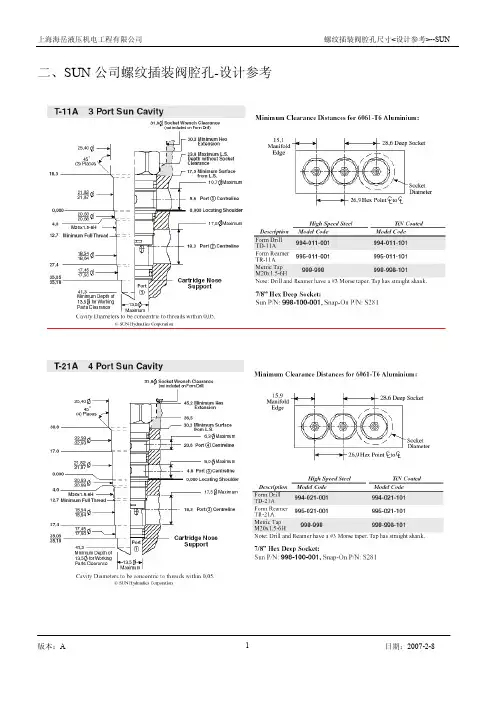
液压插装阀孔sae标准概述说明以及解释1. 引言概述:液压插装阀孔是一种常用的连接元件,在液压系统中起着至关重要的作用。
SAE (美国汽车工程师学会)标准是行业内广泛采用的规范,对液压插装阀孔的设计、尺寸以及材料要求进行了详细说明和解释。
文章结构:本文将以"液压插装阀孔sae标准概述说明以及解释"为题,从以下几个方面进行论述:首先简要介绍SAE标准的背景和重要性,然后详细说明液压插装阀孔的定义和在液压系统中的作用。
接下来,深入解析SAE J518系列标准,并探讨插装阀到液压管路的连接方式和尺寸要求,以及阀孔表面粗糙度和材质要求。
最后,对液压插装阀孔相关参数进行解释,包括阀座直径和安装宽度、螺纹类型和尺寸、以及阀板阻塞面积和流量特性等。
目的:通过本文的撰写,旨在全面介绍和解释液压插装阀孔的SAE标准,使读者对该标准有一个清晰的认识和了解。
同时,通过对液压插装阀孔相关参数的解释,帮助读者更好地理解和应用这些标准要求。
最终达到促进液压领域相关技术研究发展的目标。
2. 液压插装阀孔sae标准概述2.1 SAE标准简介SAE是国际汽车工程师学会(Society of Automotive Engineers)的缩写,该组织负责制定和发布汽车工程领域的标准。
液压插装阀孔sae标准是为了规范液压系统中插装阀孔的设计、尺寸和性能而制定的。
2.2 液压插装阀孔的定义液压插装阀孔是指液压系统中用于安装插装阀的孔或通道。
这些阀可用于控制流体的流动方向、压力和流量等参数。
插装阀孔通常位于液压管路中,具有固定的直径和深度尺寸。
2.3 插装阀孔在液压系统中的作用液压插装阀孔在液压系统中起到重要作用。
它们允许通过管路安装各种类型的插装阀,使得对流体流动进行精确控制成为可能。
通过合理配置和安装插装阀,可以实现对液压系统各部分进行连接、转换、调节和保护等功能。
总之,液压插装阀孔sae标准概述了SAE组织制定的液压插装阀孔的设计、尺寸和性能要求。
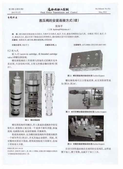
螺纹插装阀技术螺纹插装阀技术张海平2006-11目录目录前言1. 各类螺纹插装阀:构造,工作原理和性能2. 发展历史与现状3. 螺纹插装阀的应用4. 螺纹插装阀的局限性前言前言螺纹插装阀具有体积小、结构紧凑、应用灵活、使用方便、价格低等一系列优点,在欧美被广泛应用在农机、废物处理、起重机、拆卸设备、钻井、铲车、公路建设、消防车、林业机械、轮船、油井、矿井、扫路车、挖掘机、多用途车、金属切削、金属成型、机械手、铸造、成型、造纸、纺织、包装设备、动力单元、试验台等。
1. 各类螺纹插装阀:构造各类螺纹插装阀:构造,工作原理和性能,工作原理和性能,工作原理和性能插装阀(Cartridge Valve)从安装方式上可分为滑入式(Slip-in)和螺旋式(Screw-in)这两类。
滑入式即通常所称的二通插装阀或逻辑元件,它一般都还需要附加先导控制阀才能工作。
螺旋式即本文要述及的螺纹插装阀,它(装入安装孔后)一般都能独立完成一个或多个液压功能,如溢流阀、电磁方向阀、流量控制阀、平衡阀等。
以下摘取自一些国际市场上可见产品的使用说明书,供读者具体了解螺纹插装阀。
1.1单向阀单向阀Sterling 公司的D02B2:工作压力42MPa,最大流量80升/分,总长33.7mm,安装孔内部分长27.2mm。
1.2 溢流阀Sterling公司的A04R2M:工作压力0.5-35MPa,最大流量60升/分,总长123mm,安装孔内部分长46mm,直径22mm。
1.1.33电磁方向阀电磁方向阀::滑阀滑阀Hydraforce 公司的SV10-47C:工作压力21MPa,最大流量22升/分,总长188mm,孔内部分长62mm,直径22mm。
驱动线圈功率24W。
座阀座阀Sterling 公司的GS0408:工作压力35MPa,最大流量75升/分,总长94mm,孔内部分长33mm,直径22mm。
驱动线圈功率19W。
1.4 流量控制阀流量控制阀二通式:Hydraforce 公司的FR12-23,工作压力24MPa,最大流量77升/分,总长107mm,安装孔内部分长61mm,直径25mm。
安装孔内部分长74mm,直径30mm。
平衡阀1.1.55平衡阀SUN公司有很丰富的平衡阀品种,这里是其中一类,工作压力28MPa,最大流量480升/分。
比例压力阀1.6 比例压力阀Sterling公司的AP04G2YR,工作压力35MPa,最大流量95升/分,总长90mm,安装孔内部分长32mm,直径22mm。
比例流量阀1.1.77比例流量阀Hydraforce 公司的PV72-30,工作压力21MPa,最大流量64升/分,总长156mm,安装孔内部分长71mm,直径25mm。
由于螺纹插装阀结构相对简单,加工容易,通用件多,便于大批量生产,因此价格比相同功能的板式阀,管式阀低一些。
发展历史与现状发展历史与现状2.2.发展历史与现状液压出现于20世纪初,大发展则在二次大战期间。
1950年在美国出现了最早的螺纹插装阀—为美国空军,装在飞机燃料泵体上的溢流阀。
但直到60年代初,螺纹插装阀还局限于简单的功能,如止回阀,溢流阀和二位二通电磁阀。
由于重量轻,空间紧凑,被应用于农业、采矿,航海和建筑机械等中压低流量的场合。
在1970年前后,当时螺纹插装阀的主要生产商Fluid Control在欧美各地的代理商,纷纷建立了自己的生产基地和设计机构,发展自己的产品。
例如,Modular, Sun, Sterling, Wandflu, Comatrol等。
螺纹插装阀出现了大发展。
由于螺纹插装阀可以有4端口,甚至6端口,因此相对二通插装阀有大得多的变化可能性。
到了80年代,形成了全方位供应商,被市场普遍接受。
迄今世界上已有上百家公司可以提供螺纹插装阀、阀块,并为顾客设计专用集成块。
主要基地在美国的有Hydraforce、Sun hydraulics、Fluid Power Systems、Delta Power、Waterman-Parker Hannifin、Fluid Control (Danfoss)、Eaton-Vickers等,在英国的有Sterling hydraulics、Integrated hydraulics,在瑞士的有Wandfluh、Bucher-Frutigen,在意大利的有Comatrol、Oil-Control,在德国的有Bosch-Rexroth、HYDAC、IMAV、Tries、Fluid Team等等。
其中许多厂的螺纹插装阀及阀块的年销售值都达到几千万乃至上亿美元。
2002年,仅Bosch-Rexroth集团一家就生产了350万件螺纹插装阀。
螺纹插装阀经过许许多多大大小小公司成千上万的技术人员持续研究改良几十年,品种纷繁。
例如,Integrated Hydraulics 公司2003年的产品样本有约300页,260种基本类型,SUN 公司2001/02年的产品样本有四百余页,约280种基本类型;ST 公司2003年的产品样本有585页,约320种基本类型;HF 公司2003年的产品样本约900页,介绍了约400类产品。
他们为顾客提供特殊设计的产品品种还数倍于此。
例如, 溢流阀溢流阀普通溢流阀:直动型(a1) 球阀型、锥阀型、带增强阻尼型、侧面入流型、滑阀型、先导型(a2);压力保险阀(b1); 带反向单向阀的溢流阀(c1);双向型溢流阀(d1, d2);遥控型溢流阀:失压卸荷型(e1)、加压卸荷型(e2)、卸荷加压型(e3) 、气控比例(e4)、电控开关型(e5),电控比例型(e6、e7)。
还有许多特种溢流阀,如埋入式热保护,双通道先导用溢流阀,软溢流阀。
图2.2.1 1 1 各类制作成螺纹插装形式的溢流阀各类制作成螺纹插装形式的溢流阀各类制作成螺纹插装形式的溢流阀顺序阀顺序阀..图2.2.22 各类制作成螺纹插装形式的顺序阀二通常闭型顺序阀:普通型(a1)、保险型(a2)、加压开启型(a3)、加压卸荷型(a4)、带反向单向阀型 (a5)、气控比例型(a6);二通常开型顺序阀:加压关闭型(b3)、加压卸荷关闭型(b4);三通型顺序阀:普通型(c1)、保险型(c2)、外加压换向型(c3);平衡阀2.33各类制作成螺纹插装形式的平衡阀图2.a1)普通三通口型 a2)控制口带附加阻尼型 a3)带附加溢流阀型b1)四通口,带单独背压出口型 b2)无背压(背压通大气)型 b3)无背压无溢流阀型 电磁阀反向仅有少量泄漏 双向可通1a2a-.2 二位二通常闭型电磁阀的大致类型二位二通常闭型电磁阀的大致类型二位二通常闭型电磁阀的大致类型得电3关闭但不完全密封 仅单向关闭密封,反向可通关闭且双向密封3b表2.3.3 二位二通常开型电磁阀的大致类型二位二通常开型电磁阀的大致类型二位二通常开型电磁阀的大致类型a b cd ef1 f2 g图2.4二位三通的图形符号二位三通的图形符号这些生产商各有特色,相互竞争,相互学习。
没有生产商能够提供所有类型。
精益求精,不断创新已有宽广的产品型谱,相当的可靠性。
但还在不断改进,不断扩展,每年推出新产品,追求完美。
•平衡阀不同阻力特性,以适应不同负载速度的需要流量曲线节流特性不同的阀的控制压力--流量曲线图2.5节流特性不同的阀的控制压力•软溢流阀有效消除压力尖峰工作原理图2.6 工作原理图图2.6高集成度Integrated 液控单向阀x2 +溢流阀2.7 图形符号图形符号图2.7图2.8结构图3. 螺纹插装阀的应用螺纹插装阀的最大特点是应用灵活。
它可以单独装入与其配用的单阀块或双阀块(阀供货商一般都能同时提供这类阀块),成为管式元件。
它也可以装入液压马达、液压泵体,或液压缸接口处,作为控制阀。
它也可以装入带CETOP接口的阀块,成为竖式叠加阀、或横向片状组装阀。
它也可以装入二通插装阀的控制盖板,作为先导控制。
最后,它也可以装入自行设计的专用(纯)螺纹插装阀集成块,例如以下三个由笔者自行或指导设计的阀块。
例一。
这个回路可以控制一组单向液压缸,按预设定的速度升,靠自重降。
最大输入流量可达70升/分,输出流量0至30升/分,压力至21Mpa。
7个螺纹插装阀(Sterling公司)。
铝合金阀块135X 135X60mm,连阀占用空间245X225X 60mm。
例一例二。
这个回路使用比例流量阀和比例溢流阀,可以控制两组单向液压缸,独立或并行,按给定的速度升,靠自重降,限速,可调。
最大输入流量可达60升/分,两路输出流量分别为0至22升/分,压力至21Mpa。
10个螺纹插装阀,多为Hydraforce产品。
铝合金阀块140X140X80mm,连阀占用空间280X230X80mm。
例一和例二的纵向都限制在80mm以下,垂直和水平向所允许的空间也极其有限,包括其一些功能要求,都是用普通的管式和板式阀是很难实现的。
例二例三。
前二例皆为电控,此阀块系为配合手动阀而设计,可以分别控制两组半双向液压缸,按预设定的速度和压力升出和收回。
最大输入流量可达40升/分,压力至21Mpa。
14个螺纹插装阀,使用SUN和Sterling等的产品,铝合金阀块90X90 X198mm。
连阀占用空间90X186X288mm。
四个与阀连接的接口间距与阀的出口间距相同,因此可以用短直管连接。
比以前使用管式阀大大缩小了占用空间,缩短了组装时间,特别是在装配流水线上的组装时间,减少了可能泄漏的部位数,降低了管道与接头引起的压力损失,便于整块更换,降低了对现场维修人员的技术水平要求,缩短系统停工期。
例三螺纹插装阀的局限性4. 螺纹插装阀的局限性当然,螺纹插装阀也有其局限性,表现在以下几方面。
互换性差4.1互换性差除电磁线圈不兼容以外,安装孔也不一样,不能简单换。
从1982年起,就在蕴酿制定国际标准,统一安装孔形式,以改善互换性,但直到1998年使用公制螺纹的ISO7789才获多数通过。
但仅两年后,12个美国螺纹插装阀生产商就又提出了一个使用UN(Unified Coarse thread)和UNF(Unified Fine thread)螺纹的国际标准草案CAD17209,得到了不少赞成票,但在美国有重要市场地位的SUN公司既未参加也未拒绝。
欧洲许多专家则表示反对,一是认为安全问题未得到足够重视,二是反对一个产品两个标准。
另一方面ISO7789的市场化进展也非常缓慢,至今仍无一家公司推出完整的ISO系列阀。
正如所比喻的,“火车已经(向四面八方)开走了,”再要它们回到一条轨道上来,就很难了。
中小流量4.4.22中小流量由于螺纹强度和紧固扭矩的限制(500Nm),螺纹插装阀的直径只能做到48mm,相应于二通插装阀通径16,25,流量400、500升/分左右,再大就是二通插装阀的天地了。