EtherChannel基本配置
- 格式:docx
- 大小:255.90 KB
- 文档页数:4
EtherChannel(PAgP、LACP)基本配置--端⼝聚合--(转)EtherChannelEtherChannel(以太通道)也叫端⼝聚合或链路聚合,特别提⼀下。
建议我们在使⽤中,物理链路的汇聚,我们可以叫链路(端⼝)汇聚或链路(端⼝)聚合。
⽽VLAN的中继聚合,我们叫vlan聚合或VLAN汇聚,或直接叫trunk! 很容易搞混哦!是由Cisco研发的,应⽤于交换机之间的多链路捆绑技术。
它的基本原理是:将两个设备间多条相同特性的快速以太或千兆位以太物理链路捆绑在⼀起组成⼀条逻辑链路,从⽽达到带宽倍增的⽬的。
除了增加带宽外,EtherChannel还可以在多条链路上均衡分配流量,起到负载分担的作⽤;当⼀条或多条链路故障时,只要还有链路正常,流量将转移到其它的链路上,整个过程在⼏毫秒内完成,从⽽起到冗余的作⽤,增强了⽹络的稳定性和安全性。
在EtherChannel中,负载在各个链路上的分布可以根据源IP地址、⽬的IP地址、源MAC地址、⽬的MAC地址、源IP地址和⽬的IP地址组合,以及源MAC地址和⽬的MAC地址组合等来进⾏分布。
两台交换机之间是否形成EtherChannel也可以⽤协议⾃动协商。
⽬前有两个协商协议:PAgP和LACP,PAgP(端⼝汇聚协议 Port Aggregation Protocol)是Cisco私有的协议,⽽LACP(链路汇聚控制协议 Link Aggregation Control Protocol)是基于IEEE 802.3ad的国际标准。
能形成EtherChannel的模式总结:EtherChannel命令组合:如果想把端⼝配置为on:sw1(config-if-range)#channel-group 1 mode on如果想把端⼝配置为PAgP的desirable:sw1(config-if-range)#channel-protocol pagpsw1(config-if-range)#channel-group 1 mode desirable如果想把端⼝配置为PAgP的auto:sw1(config-if-range)#channel-protocol pagpsw1(config-if-range)#channel-group 1 mode auto如果想把端⼝配置为LACP的active:sw1(config-if-range)#channel-protocol lacpsw1(config-if-range)#channel-group 1 mode active如果想把端⼝配置为LACP的passive:sw1(config-if-range)#channel-protocol lacpsw1(config-if-range)#channel-group 1 mode passiveEtherChannel说明:①Cisco最多允许EtherChannel绑定8个端⼝;1>如果是快速以太⽹,总带宽可达1600Mbit/s;2>如果是Gbit以太⽹,总带宽可达16Gbit/s。

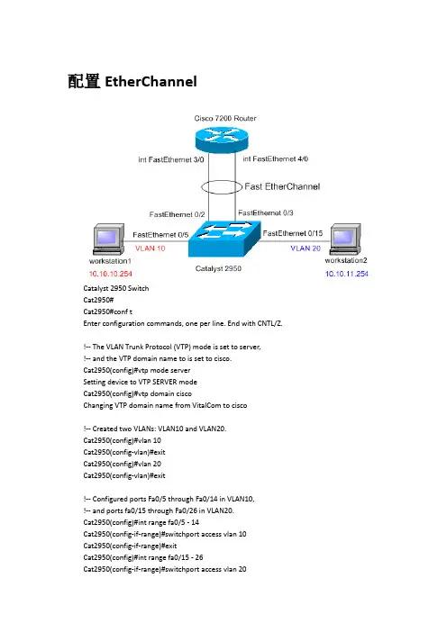
配置EtherChannelCatalyst 2950 SwitchCat2950#Cat2950#conf tEnter configuration commands, one per line. End with CNTL/Z.!-- The VLAN Trunk Protocol (VTP) mode is set to server,!-- and the VTP domain name to is set to cisco.Cat2950(config)#vtp mode serverSetting device to VTP SERVER modeCat2950(config)#vtp domain ciscoChanging VTP domain name from VitalCom to cisco!-- Created two VLANs: VLAN10 and VLAN20.Cat2950(config)#vlan 10Cat2950(config-vlan)#exitCat2950(config)#vlan 20Cat2950(config-vlan)#exit!-- Configured ports Fa0/5 through Fa0/14 in VLAN10,!-- and ports fa0/15 through Fa0/26 in VLAN20.Cat2950(config)#int range fa0/5 - 14Cat2950(config-if-range)#switchport access vlan 10Cat2950(config-if-range)#exitCat2950(config)#int range fa0/15 - 26Cat2950(config-if-range)#switchport access vlan 20Cat2950(config-if-range)#^ZCat2950#00:32:39: %SYS-5-CONFIG_I: Configured from console by console!-- Configured the management interface so that the switch!-- can be accessed remotely by using Telnet.Cat2950#conf tCat2950(config)#int vlan 10Cat2950(config-if)#ip address 10.10.10.10 255.255.255.0Cat2950(config-if)#no shutdown00:24:07: %LINK-3-UPDOWN: Interface Vlan10, changed state to upCat2950(config-if)#^Z00:24:12: %SYS-5-CONFIG_I: Configured from console by consoleCat2950#conf tEnter configuration commands, one per line. End with CNTL/Z.!-- Configured the default-gateway, which is the IP address of the sub-interface!-- on the router for VLAN 10, so that the switch can be accessed from any VLAN.Cat2950(config)#ip default-gateway 10.10.10.1!-- Configured a logical channel interface.Cat2950(config)#int port-channel 1Cat2950(config-if)#exit!-- Ports are assigned to the logical channel interface to form an EtherChannel.!-- Note: The channel mode on the switch is set to on because the Cisco 7200!-- router on the other end does not support Port Aggregation Protocol(PAgP).Cat2950(config)#int fa0/2Cat2950(config-if)#channel-group 1 mode onCat2950(config-if)#exitCat2950(config)#00:25:38: %LINK-3-UPDOWN: Interface Port-channel1, changed state to up00:25:39: %LINEPROTO-5-UPDOWN: Line protocol on Interface Port-channel1, changed state to upCat2950(config)#int fa0/3Cat2950(config-if)#channel-group 1 mode onCat2950(config-if)#exit!-- To configure trunking over EtherChannel, trunking!-- is enabled over the logical channel interface.Cat2950(config)#int port-channel 1Cat2950(config-if)#switchport mode trunkCat2950(config-if)#!-- Configured VLAN10 as the Native VLAN for untagged traffic.Cat2950(config-if)#switchport trunk native vlan 10Cat2950(config-if)#^Z00:24:12: %SYS-5-CONFIG_I: Configured from console by consoleCat2950#Cisco 7200 RouterCisco7200#Cisco7200#conf tEnter configuration commands, one per line. End with CNTL/Z.!-- Created a logical channel interface to form an EtherChannel.Cisco7200(config)#int port-channel 1Cisco7200(config-if)#exit!-- The ports fa3/0 and fa4/0 are configured as members of the!-- logical channel to form an EtherChannel group.Cisco7200(config)#int fa3/0Cisco7200(config-if)#channel-group 1FastEthernet3/0 added as member-1 to port-channel1Cisco7200(config-if)#exitCisco7200(config)#Cisco7200(config)#int fa4/0Cisco7200(config-if)#channel-group 1FastEthernet4/0 added as member-2 to port-channel1Cisco7200(config-if)#exit!-- Configured sub-interfaces over port-channel for VLAN10 and VLAN20 to configure !-- trunking over EtherChannel. The IP address is assigned to InterVLAN routing.!-- Configured VLAN10 as the Native VLAN for untagged traffic.Cisco7200(config)#int port-channel 1.10Cisco7200(config-subif)#encapsulation dot1Q 10 nativeCisco7200(config-subif)#ip address 10.10.10.1 255.255.255.0Cisco7200(config-subif)#exitCisco7200(config)#int port-channel 1.20Cisco7200(config-subif)#encapsulation dot1Q 20Cisco7200(config-subif)#ip address 10.10.11.1 255.255.255.0Cisco7200(config-subif)#exitCisco7200(config)#exitCisco7200#EtherChanneletherchannel特性在switch到switch、switch到router之间提供冗余的、高速的连接方式,简单说就是将两个设备间多条FE或GE物理链路捆在一起组成一条设备间逻辑链路,从而达到增加带宽,提供冗余的目的。

实验2.5 EtherChannel的配置1.实验目的通过实验可以掌握:(1)EtherChannel的工作原理(2)EtherChannel的配置2.实验拓扑EtherChannel配置实验拓扑如图2-1所示。
图2-1 EtherChannel配置实验拓扑3.实验步骤构成EtherChannel的端口必须具有相同的特性:Trunking的状态、Trunk的封装方式、双工、速率及所属的VLAN等。
配置EtherChannel有手动配置和自动配置(PAGP或者LACP)两种方法。
手动配置就是管理员指明哪些接口形成EtherChannel;自动配置就是让EtherChannel协商协议自动协商EtherChannel的建立,协商的协议有PAGP或者LACP两种。
(1)手动配置EtherChannelS1(config)#int f0/13S1(config-if)#shutdown//关闭不必要的接口,否则会影响测试S1(config)#int port-channel ?<1-48> Port-channel interface numberS1(config)#int port-channel 1//创建以太通道,需指定一个唯一的通道组号,组号的范围是1~48的正整数。
要取消EtherChannel时用“no interface port-channel 1”S1(config)#int range f0/14-15S1(config-if-range)#channel-group 1 mode ?active Enable LACP unconditionallyauto Enable PAgP only if a PAgP device is detecteddesirable Enable PAgP unconditionallyon Enable Etherchannel onlypassive Enable LACP only if a LACP device is detectedS1(config-if-range)#channel-group 1 mode on//将物理接口指定到已创建的通道中S1(config-if-range)#switchport trunk encapsulation dot1qS1(config-if-range)#switchport mode trunk//配置通道中的物理接口的属性,这里是配置trunkS1(config)#port-channel load-balance ?dst-ip Dst IP Addrdst-mac Dst Mac Addrsrc-dst-ip Src XOR Dst IP Addrsrc-dst-mac Src XOR Dst Mac Addrsrc-ip Src IP Addrsrc-mac Src Mac AddrS1(config)#port-channel load-balance dst-ip//配置EtherChannel的负载平衡方式S2(config)#int port-channel 2//链路两端的channel-group是可以不一样的,这个百年好只是本地有效。
Etherchannel介绍在AIX操作系统中,用户可以配置多个EtherChannel(网卡绑定)。
在AIX 5.2之前,我们要么只能选择active/active EtherChannel模式,要么,只能选择active/standby EtherChannel模式的绑定网卡。
所以,AIX 5.2中引入了新的网卡后备模式,用户可以为整个EtherChannel指定一块备份网卡,当整个EtherChannel失效时,这块网卡会自动顶替EtherChannel的功能。
这与AIX 5.2之前的EtherChannel网卡备份模式有很大区别,因此,在5.2以后可以出现更为复杂的复合网卡绑定模式。
一个EtherChannel中可以有2到8块网卡,一个AIX操作系统中可以配置多个EtherChannel。
但要记住每个EtherChannel都是一个新的以太网接口,用户也许需要通过no命令调整ifsize参数的值来保证以太网卡和EtherChannel的总数不超过ifsize,ifsize的默认值是8。
您可以使用任何AIX系统支持的网卡来组建EtherChannel。
但EtherChannel 的同一个通道成员网卡必须连接到支持EtherChannel的交换机上,备用通道可以接入到另外一个交换机,用于主通道的失败接管。
EtherChannel的所有成员网卡都应该设置成同样的速度和工作模式,如1000兆全双工。
要用作EtherChannel成员的网卡不能配置IP地址,如果已经配置了,必须要在开始配置EtherChannel前删除这些配置。
在Aix5.2以后,我们看看三种典型的配置方式1、双通道或者多通道的共同active模式,这个模式下,所有的网卡都处于active状态,也就是每个网卡都处于工作状态,他们共有一个IP地址与MAC地址,但是,所有网卡的目标必须在同一个交换机上,并且交换机的对应端口也要绑定。
这样做最大的好处就是,当其中一个网卡失效,或者一根网线失效的时候,不影响整个网络的工作,只有当所有的网卡通道失效的时候,网络才失效。
![5.13 L2 Etherchannel基本配置[共4页]](https://uimg.taocdn.com/41df42122cc58bd63086bd8b.webp)

配置三层EtherChannel若欲在三层设备(如三层交换机)之间实现高速连接,可以采用三层EtherChannel方式,从而避免由路由连接而产生的瓶颈。
1.创建Port-Channel逻辑接口当将IP地址从物理接口移动至EtherChannel时,必须先从物理接口中删除该IP地址。
第一步:进入全局配置模式。
Switch# configure terminal第二步:创建Port-Channel接口。
port_channel_number取值范围为1~48。
Switch(config)# interface port-channel port_channel_number第三步:将接口置于三层模式。
Switch(config-if)# no switchport第四步:为该EtherChannel指定IP地址和子网掩码。
Switch(config-if)# ip address ip_address mask第五步:退出配置模式。
Switch(config-if)# end第六步:校验配置。
Switch# show running-config interface port-channel port_channel_number2.配置为三层EtherChannel第一步:进入全局配置模式。
Switch# configure terminal第二步:选择欲配置的物理接口。
Switch(config)# interface {fastethernet | gigabitethernet} slot/port第三步:创建三层路由端口。
Switch(config-if)# no switchport第四步:确保该物理接口没有指定IP地址。
Switch(config-if)# no ip address第五步:将接口配置至port-channel,并指定PAgP或LACP模式。
Switch(config-if)# channel-group channel-group-number mode {auto [non-silent] | desirable [non-silent] | on} | {active | passive}第六步:退出配置模式。
思科Etherchannel链路聚合原理与配置⽅法详解本⽂讲述了思科Etherchannel链路聚合原理与配置⽅法。
分享给⼤家供⼤家参考,具体如下:Etherchannel(以太⽹信道)将多个(2-8,2-16)接⼝,逻辑的整合为⼀个接⼝,来转发流量,减少了阻塞端⼝的数量,提⾼了链路带宽,增加了⽹络的稳定性1.1 封装模式1.1.1 PAGP端⼝聚合协议,cisco私有,通过发送慢速hello(30s),协商成为echerchannel,最⼤⽀持在8条链路的协商,链路数量必须为2^x,2 4 8desirable:主动模式auto:auto模式包含了silent模式(安静模式),可以进⾏etherchannel协商1.1.2 LACP链路聚合控制协议(仅⽀持全双⼯接⼝),公有协议。
发送LACPDU进⾏以太信道的协商,最⼤⽀持在16条链路上进⾏以太信道协商,2 4 8 16,默认仅仅使⽤8条。
当使⽤16条链路进⾏协商,选择8条为主链路,其余8条为备份链路。
选择⽅法:1.较⼩优先级(优先级默认32768),2.最⼩的PID模式:active(主动)passive(被动)1.1.3 on模式⼿⼯模式,on模式不能与任何动态PAgP或LAGP建⽴ethechannel。
被动与被动不能形成.1.2 Ethechannel配置1.2.1 配置指南1.通道内所有端⼝必须⽀持ethechannel;同时注意必须连接相同设备(同⼀设备,同本地类型相同)2.这些物理接⼝必须具有相同的速率和双⼯模式(LACP必须为全双⼯)3.通道内不得使⽤span;若为三层通道,IP地址必须配置到逻辑接⼝上(channel-group)4.三层通道内的所有物理接⼝必须为三层接⼝,然后再channel⼝上配置IP地址5.若为⼆层通道,这些物理接⼝应该属于同⼀vlan或者均为trunk⼲道,且封装的类型⼀致,vlan的允许列表必须⼀致6.通道的属性改变将同步到物理接⼝,反之也可;若物理没有全部down,通道依然正常同时配置所有物理接⼝,或者之恶配置channel⼝,均可修改接⼝的属性1.2.2 ⼆层ethechannel配置SW1(config)#int range e0/1-2SW1(config-if-range)#channel-group 1 mode onSW1(config-if-range)#interface port-channel 1 #对逻辑接⼝进⾏管理SW1(config-if)#switchport trunk encapsulation dot1q #修改trunk封装模式SW1(config-if)#switchport mode trunk1.2.3三层ethechannel配置在没有三层ethechannel时,三层链路依然可以使⽤负载均衡来进⾏通信;建⽴三层ethechannel后,可以节省IP地址⽹段,间路路由条⽬的编辑(⼀般配置在核⼼层)SW1(config)#int range e0/1-2SW1(config-if-range)#no switchportSW1(config-if-range)#channel-group 1 mode onSW1(config-if-range)#exitSW1(config)#int port-channel 1 #在通道接⼝上配置IP地址SW1(config-if)#ip add 192.168.1.1 255.255.255.05.3 配置channel时的注意点⼆层通道基于负载分担转发流量,三层通道基于负载均衡转发流量负载均衡:访问同⼀⽬标时,将流量按为单位分割后,沿多条路径同时传输负载分担:访问不同⽬标时基于不同链路,或者不同元在访问⽬标时基于不同链路基于不同源MAC(src-mac)为默认规则。
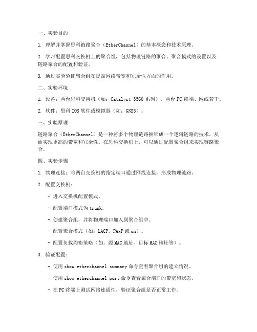
一、实验目的1. 理解并掌握思科链路聚合(EtherChannel)的基本概念和技术原理。
2. 学习配置思科交换机上的聚合组,包括物理链路的聚合、聚合模式的设置以及链路聚合的配置和验证。
3. 通过实验验证聚合组在提高网络带宽和冗余性方面的作用。
二、实验环境1. 设备:两台思科交换机(如:Catalyst 3560系列)、两台PC终端、网线若干。
2. 软件:思科IOS软件或模拟器(如:GNS3)。
三、实验原理链路聚合(EtherChannel)是一种将多个物理链路捆绑成一个逻辑链路的技术,从而实现更高的带宽和冗余性。
在思科交换机上,可以通过配置聚合组来实现链路聚合。
四、实验步骤1. 物理连接:将两台交换机的指定端口通过网线连接,形成物理链路。
2. 配置交换机:- 进入交换机配置模式。
- 配置端口模式为trunk。
- 创建聚合组,并将物理端口加入到聚合组中。
- 配置聚合模式(如:LACP、PAgP或on)。
- 配置负载均衡策略(如:源MAC地址、目标MAC地址等)。
3. 验证配置:- 使用show etherchannel summary命令查看聚合组的建立情况。
- 使用show etherchannel port命令查看聚合端口的带宽和状态。
- 在PC终端上测试网络连通性,验证聚合组是否正常工作。
五、实验结果与分析1. 聚合组建立情况:通过show etherchannel summary命令,可以看到聚合组的建立情况,包括聚合组ID、端口状态、链路状态等。
2. 聚合端口带宽:通过show etherchannel port命令,可以看到聚合端口的带宽和状态,包括端口聚合状态、带宽利用率等。
3. 网络连通性测试:在PC终端上测试网络连通性,可以发现聚合组正常工作,提高了网络带宽和冗余性。
六、实验总结通过本次实验,我们成功配置了思科交换机上的聚合组,并验证了其在提高网络带宽和冗余性方面的作用。
实验结果表明,链路聚合是一种有效的网络技术,可以满足大型网络对带宽和可靠性的需求。
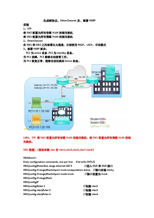
生成树协议,EtherChannel及、部署HSRP实验1、STP将SW2配置为所有奇数VLAN的根交换机将SW1配置为所有偶数VLAN的根交换机2、EtherChannel在SW1和SW2之间部署以太通道,分别使用PAGP、LACP、手动模式3、部署HSRP要求:PC1为active设备PC2为standby设备。
当PC1故障,PC2能够自动接替工作。
当PC1恢复正常,能够自动切换回Active状态。
LAB1:STP 将SW2配置为所有奇数VLAN的根交换机,将SW1配置为所有偶数VLAN的根交换机。
SW1配置:(假设奇数vlan有vlan1,vlan3,vlan5,vlan7,vlan9)SW1#conf tEnter configuration commands, one per line. End with CNTL/Z.SW1(config)#interface range ethernet 0/2-3 //进入E0/2和E0/3接口SW1(config-if-range)#switchport trunk encapsulation dot1q //接口封装dot1qSW1(config-if-range)#switchport mode trunk //接口设置为trunkSW1(config-if-range)#exitSW1(config)#SW1(config)#vlan 2 //创建vlan2SW1(config-vlan)#vlan 3 //创建vlan3SW1(config-vlan)#vlan 4 //创建vlan4SW1(config-vlan)#vlan 5 //创建vlan5SW1(config-vlan)#vlan 6 //创建vlan6SW1(config-vlan)#vlan 7 //创建vlan7SW1(config-vlan)#vlan 8 //创建vlan8SW1(config-vlan)#vlan 9 //创建vlan9SW1(config-vlan)#vlan 10 //创建vlan10SW1(config-vlan)#exitSW1(config)#spanning-tree mode mst //设置spanning-tree模式为mst SW1(config)#spanning-tree mst configuration //进入mst配置SW1(config-mst)#instance 1 vlan 1,3,5,7,9 //设置实例instance 1 关联奇数vlan SW1(config-mst)#instance 2 vlan 2,4,6,8,10 //设置实例instance 2关联奇数vlan SW1(config-mst)#name cisco //设置域名SW1(config-mst)#revision 1 //设置修订号SW1(config-mst)#exitSW1(config)#spanning-tree mst 1 root primary //设置mst 1本交换机的为根交换机SW1(config)#SW2配置:(假设偶数vlan有vlan2,vlan4,vlan6,vlan8.vlan10)SW2#conf tEnter configuration commands, one per line. End with CNTL/Z.SW2(config)#interface range ethernet 0/2-3 //进入E0/2和E0/3接口SW2(config-if-range)#switchport trunk encapsulation dot1q //接口封装dot1qSW2(config-if-range)#switchport mode trunk //接口设置为trunkSW2(config-if-range)#exitSW2(config)#SW2(config)#vlan 2 //创建vlan2SW2(config-vlan)#vlan 3 //创建vlan3SW2(config-vlan)#vlan 4 //创建vlan4SW2(config-vlan)#vlan 5 //创建vlan5SW2(config-vlan)#vlan 6 //创建vlan6SW2(config-vlan)#vlan 7 //创建vlan7SW2(config-vlan)#vlan 8 //创建vlan8SW2(config-vlan)#vlan 9 //创建vlan9SW2(config-vlan)#vlan 10 //创建vlan10SW2(config-vlan)#exitSW2(config)#spanning-tree mode mst //设置spanning-tree模式为mst SW2(config)#spanning-tree mst configuration //进入mst配置SW2(config-mst)#instance 1 vlan 1,3,5,7,9 //设置实例instance 1 关联奇数vlan SW2(config-mst)#instance 2 vlan 2,4,6,8,10 //设置实例instance 2关联奇数vlan SW2(config-mst)#name cisco //设置域名SW2(config-mst)#revision 1 //设置修订号SW2(config-mst)#exitSW2(config)#spanning-tree mst 2 root primary //设置mst 2本交换机的为根交换机SW2(config)#结果查看:LAB2: EtherChannel 在SW1和SW2之间部署以太通道,分别使用PAGP、LACP、手动模式.SW1配置:(手动模式)SW1>enable //用户模式进入到特权模式SW1#configure terminal //特权模式进入到全局配置模式Enter configuration commands, one per line. End with CNTL/Z.SW1(config)#interface range ethernet 0/2-3 //进入接口E0/2和E0/3SW1(config-if-range)#switchport trunk encapsulation dot1q //接口封装dot1qSW1(config-if-range)#switchport mode trunk //接口模式设置为trunkSW1(config-if-range)#shutdown //关闭接口SW1(config-if-range)#*Oct 27 17:19:17.164: %LINK-5-CHANGED: Interface Ethernet0/2, changed state toadministratively down*Oct 27 17:19:17.165: %LINK-5-CHANGED: Interface Ethernet0/3, changed state to administratively down*Oct 27 17:19:18.165: %LINEPROTO-5-UPDOWN: Line protocol on Interface Ethernet0/2, changed state to down*Oct 27 17:19:18.165: %LINEPROTO-5-UPDOWN: Line protocol on Interface Ethernet0/3, changed state to downSW1(config-if-range)#channel-group 6 mode on //手动开启channel通道Creating a port-channel interface Port-channel 6SW1(config-if-range)#no shutdown //开启接口SW1(config-if-range)#*Oct 27 17:19:51.060: %LINK-3-UPDOWN: Interface Ethernet0/2, changed state to up*Oct 27 17:19:51.060: %LINK-3-UPDOWN: Interface Ethernet0/3, changed state to upSW1(config-if-range)#*Oct 27 17:19:53.076: %LINEPROTO-5-UPDOWN: Line protocol on Interface Ethernet0/2, changed state to up*Oct 27 17:19:53.076: %LINEPROTO-5-UPDOWN: Line protocol on Interface Ethernet0/3, changed state to upSW1(config-if-range)#*Oct 27 17:19:55.080: %LINEPROTO-5-UPDOWN: Line protocol on Interface Port-channel6, changed state to upSW1(config-if-range)#SW2配置:(手动模式)SW2>enable //用户模式进入到特权模式SW2#configure terminal //特权模式进入到全局配置模式Enter configuration commands, one per line. End with CNTL/Z.SW2(config)#interface range ethernet 0/2-3 //进入接口E0/2和E0/3SW2(config-if-range)#switchport trunk encapsulation dot1q //接口封装dot1qSW2(config-if-range)#switchport mode trunk //接口模式设置为trunkSW2(config-if-range)#shutdown //关闭接口SW2(config-if-range)#*Oct 27 17:17:31.191: %LINK-5-CHANGED: Interface Ethernet0/2, changed state to administratively down*Oct 27 17:17:31.191: %LINK-5-CHANGED: Interface Ethernet0/3, changed state to administratively down*Oct 27 17:17:32.195: %LINEPROTO-5-UPDOWN: Line protocol on Interface Ethernet0/2, changed state to down*Oct 27 17:17:32.195: %LINEPROTO-5-UPDOWN: Line protocol on Interface Ethernet0/3, changed state to downSW2(config-if-range)#channel-group 6 mode on //手动开启channel通道Creating a port-channel interface Port-channel 6SW2(config-if-range)#no shutdown //开启接口*Oct 27 17:19:57.829: %LINK-3-UPDOWN: Interface Ethernet0/2, changed state to up*Oct 27 17:19:57.829: %LINK-3-UPDOWN: Interface Ethernet0/3, changed state to up*Oct 27 17:19:58.835: %LINEPROTO-5-UPDOWN: Line protocol on Interface Ethernet0/2, changed state to up*Oct 27 17:19:58.836: %LINEPROTO-5-UPDOWN: Line protocol on Interface Ethernet0/3, changed state to upSW2(config-if-range)#*Oct 27 17:20:01.829: %LINEPROTO-5-UPDOWN: Line protocol on Interface Port-channel6, changed state to upSW2(config-if-range)#etherchannel通道查看:SW1和SW2配置(PAGP模式)SW1配置:SW1>enable //用户模式进入到特权模式SW1#configure terminal //特权模式进入到全局配置模式Enter configuration commands, one per line. End with CNTL/Z.SW1(config)#interface range ethernet 0/2-3 //进入接口E0/2和E0/3SW1(config-if-range)#switchport trunk encapsulation dot1q //接口封装dot1qSW1(config-if-range)#switchport mode trunk //接口模式设置为trunkSW1(config-if-range)#shutdown //关闭接口SW1(config-if-range)#*Oct 27 17:19:17.164: %LINK-5-CHANGED: Interface Ethernet0/2, changed state to administratively down*Oct 27 17:19:17.165: %LINK-5-CHANGED: Interface Ethernet0/3, changed state to administratively down*Oct 27 17:19:18.165: %LINEPROTO-5-UPDOWN: Line protocol on Interface Ethernet0/2, changed state to down*Oct 27 17:19:18.165: %LINEPROTO-5-UPDOWN: Line protocol on Interface Ethernet0/3, changed state to downSW1(config-if-range)#channel-group 8 mode desirable //开启channel通道协商Creating a port-channel interface Port-channel 8SW1(config-if-range)#no shutdown //开启接口SW1(config-if-range)#*Oct 27 17:19:51.060: %LINK-3-UPDOWN: Interface Ethernet0/2, changed state to up*Oct 27 17:19:51.060: %LINK-3-UPDOWN: Interface Ethernet0/3, changed state to upSW1(config-if-range)#*Oct 27 17:19:53.076: %LINEPROTO-5-UPDOWN: Line protocol on Interface Ethernet0/2, changed state to up*Oct 27 17:19:53.076: %LINEPROTO-5-UPDOWN: Line protocol on Interface Ethernet0/3, changed state to upSW1(config-if-range)#*Oct 27 17:19:55.080: %LINEPROTO-5-UPDOWN: Line protocol on Interface Port-channel8, changed state to upSW1(config-if-range)#SW2配置:SW2>enable //用户模式进入到特权模式SW2#configure terminal //特权模式进入到全局配置模式Enter configuration commands, one per line. End with CNTL/Z.SW2(config)#interface range ethernet 0/2-3 //进入接口E0/2和E0/3SW2(config-if-range)#switchport trunk encapsulation dot1q //接口封装dot1qSW2(config-if-range)#switchport mode trunk //接口模式设置为trunkSW2(config-if-range)#shutdown //关闭接口SW2(config-if-range)#*Oct 27 17:17:31.191: %LINK-5-CHANGED: Interface Ethernet0/2, changed state to administratively down*Oct 27 17:17:31.191: %LINK-5-CHANGED: Interface Ethernet0/3, changed state to administratively down*Oct 27 17:17:32.195: %LINEPROTO-5-UPDOWN: Line protocol on Interface Ethernet0/2, changed state to down*Oct 27 17:17:32.195: %LINEPROTO-5-UPDOWN: Line protocol on Interface Ethernet0/3,changed state to downSW2(config-if-range)#channel-group 8 mode desirable //开启channel通道协商Creating a port-channel interface Port-channel 8SW2(config-if-range)#no shutdown //开启接口*Oct 27 17:19:57.829: %LINK-3-UPDOWN: Interface Ethernet0/2, changed state to up*Oct 27 17:19:57.829: %LINK-3-UPDOWN: Interface Ethernet0/3, changed state to up*Oct 27 17:19:58.835: %LINEPROTO-5-UPDOWN: Line protocol on Interface Ethernet0/2, changed state to up*Oct 27 17:19:58.836: %LINEPROTO-5-UPDOWN: Line protocol on Interface Ethernet0/3, changed state to upSW2(config-if-range)#*Oct 27 17:20:01.829: %LINEPROTO-5-UPDOWN: Line protocol on Interface Port-channel8, changed state to upSW2(config-if-range)#结果查看:SW1和SW2配置(LACP模式)SW1配置:SW1>enable //用户模式进入到特权模式SW1#configure terminal //特权模式进入到全局配置模式Enter configuration commands, one per line. End with CNTL/Z.SW1(config)#interface range ethernet 0/2-3 //进入接口E0/2和E0/3SW1(config-if-range)#switchport trunk encapsulation dot1q //接口封装dot1qSW1(config-if-range)#switchport mode trunk //接口模式设置为trunkSW1(config-if-range)#shutdown //关闭接口SW1(config-if-range)#*Oct 27 17:19:17.164: %LINK-5-CHANGED: Interface Ethernet0/2, changed state to administratively down*Oct 27 17:19:17.165: %LINK-5-CHANGED: Interface Ethernet0/3, changed state to administratively down*Oct 27 17:19:18.165: %LINEPROTO-5-UPDOWN: Line protocol on Interface Ethernet0/2, changed state to down*Oct 27 17:19:18.165: %LINEPROTO-5-UPDOWN: Line protocol on Interface Ethernet0/3, changed state to downSW1(config-if-range)#channel-group 1 mode active //开启channel通道协商Creating a port-channel interface Port-channel 1SW1(config-if-range)#no shutdown //开启接口SW1(config-if-range)#*Oct 27 17:19:51.060: %LINK-3-UPDOWN: Interface Ethernet0/2, changed state to up*Oct 27 17:19:51.060: %LINK-3-UPDOWN: Interface Ethernet0/3, changed state to upSW1(config-if-range)#*Oct 27 17:19:53.076: %LINEPROTO-5-UPDOWN: Line protocol on Interface Ethernet0/2, changed state to up*Oct 27 17:19:53.076: %LINEPROTO-5-UPDOWN: Line protocol on Interface Ethernet0/3, changed state to upSW1(config-if-range)#*Oct 27 17:19:55.080: %LINEPROTO-5-UPDOWN: Line protocol on Interface Port-channel1, changed state to upSW1(config-if-range)#SW2配置:SW2>enable //用户模式进入到特权模式SW2#configure terminal //特权模式进入到全局配置模式Enter configuration commands, one per line. End with CNTL/Z.SW2(config)#interface range ethernet 0/2-3 //进入接口E0/2和E0/3SW2(config-if-range)#switchport trunk encapsulation dot1q //接口封装dot1qSW2(config-if-range)#switchport mode trunk //接口模式设置为trunkSW2(config-if-range)#shutdown //关闭接口SW2(config-if-range)#*Oct 27 17:17:31.191: %LINK-5-CHANGED: Interface Ethernet0/2, changed state to administratively down*Oct 27 17:17:31.191: %LINK-5-CHANGED: Interface Ethernet0/3, changed state to administratively down*Oct 27 17:17:32.195: %LINEPROTO-5-UPDOWN: Line protocol on Interface Ethernet0/2, changed state to down*Oct 27 17:17:32.195: %LINEPROTO-5-UPDOWN: Line protocol on Interface Ethernet0/3, changed state to downSW2(config-if-range)#channel-group 1 mode active //开启channel通道协商Creating a port-channel interface Port-channel 1SW2(config-if-range)#no shutdown //开启接口*Oct 27 17:19:57.829: %LINK-3-UPDOWN: Interface Ethernet0/2, changed state to up*Oct 27 17:19:57.829: %LINK-3-UPDOWN: Interface Ethernet0/3, changed state to up*Oct 27 17:19:58.835: %LINEPROTO-5-UPDOWN: Line protocol on Interface Ethernet0/2, changed state to up*Oct 27 17:19:58.836: %LINEPROTO-5-UPDOWN: Line protocol on Interface Ethernet0/3, changed state to upSW2(config-if-range)#*Oct 27 17:20:01.829: %LINEPROTO-5-UPDOWN: Line protocol on Interface Port-channel1, changed state to upSW2(config-if-range)#结果查看:LAB3、部署HSRP要求:PC1为active设备PC2为standby设备。
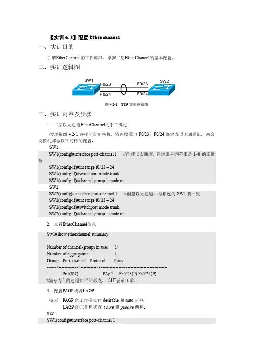
【实训4.2】配置Etherchannel一、实训目的了解EtherChannel 的工作原理,掌握二层EtherChannel 的基本配置。
二、实训逻辑图SW1F0/23F0/24图4.2-1 STP 实训逻辑图三、实训内容及步骤1.二层以太通道EtherChannel 的手工绑定:按逻辑图4.2-1连接两台交换机,将连接端口F0/23、F0/24绑定成以太通道组,两台交换机都做以下同样的配置。
SW1: SW1(config)#interface port-channel 1 //创建以太通道,通道组号的范围是1~6的正整数SW1(config-if)#int range f0/23 – 24SW1(config-if)#switchport mode trunkSW1(config-if)#channel-group 1 mode onSW2:SW2(config)#interface port-channel 1 //创建以太通道,与相连的SW1要一致 SW2(config-if)#int range f0/23 – 24SW2(config-if)#switchport mode trunkSW2(config-if)#channel-group 1 mode on2.查看EtherChannel 信息 Sw1#show etherchannel summary……Number of channel-groups in use: 1/Number of aggregators: 1Group Port-channel Protocol Ports------+-------------+-----------+----------------------------------------------1 Po1(SU) PAgP Fa0/23(P) Fa0/24(P)//编号为1的通道组已经形成,“SU”表示正常。
配置EtherChannel【提示】只有在固定端口(如双绞线端口或光纤端口)之间才能创建EtherChannel,而由GBIC或SFP插槽所创建的链路是不能用于创建EtherChannel的。
1.创建EtherChannel第一步:进入全局配置模式Switch# configure terminal第二步:选择欲配置为EtherChannel的物理接口。
PAgP EtherChannel组可以容纳8个(4对)同一类型和速度的端口。
LACP EtherChannel组最多可以容纳16个(8对)相同类型的端口,其中8个(4对)活动端口,以及最多8个(4对)备用端口。
Switch(config)# interface interface-id第三步:将所有端口指定为同一VLAN内的静态访问端口,或者配置为Trunk。
如果配置为静态端口,只能指定至一个VLAN,VLAN取值范围为1~4094。
Switch(config-if)# switchport mode {access | trunk} switchport access vlan vlan-id第四步:将接口指定至EtherChannel组,并指定PAgP或LACP模式。
EtherChannel端口组的取值范围为1~48。
PAgP或LACP模式:λauto,当侦测到PAgP设备时,将只启用PAgP。
将端口置于被动协商状态,可以对接收到的PAgP作出响应,但是,不能主动发送PAgP包进行协商。
λdesirable,无条件启用PAgP。
将接口置于主动协商状态,通过发送PAgP包,主动与其他接口进行协商。
λon,将接口强行指定至Channel。
只有两个on模式接口组连接时,EtherChannel才可用。
λnon-silent,如果交换机连接到有PAgP能力的伙伴,可以将接口配置为non silent(非沉默)运行。
如果没有为auto或desirable模式指定non-silent关键字,默认为silent。
cisco+端口链路聚合配置端口链路聚合(Port Channel)是一种将多个物理端口组合成一个逻辑链路的技术,通过增加带宽和提供冗余性,提高网络连接的可靠性和性能。
在Cisco设备上,端口链路聚合可以通过EtherChannel实现。
EtherChannel是Cisco的一种端口聚合技术,它允许将多个物理端口绑定成一个逻辑链路。
EtherChannel可以在交换机之间或交换机与服务器之间建立,可以使用不同的协议进行链路聚合,如LACP(Link Aggregation Control Protocol)或PAgP(Port Aggregation Protocol)。
下面是一个配置EtherChannel的示例:1. 配置物理接口:首先,需要将要聚合的物理接口配置为开启状态,并设置合适的速率和双工模式。
例如,假设我们要聚合的接口为GigabitEthernet1/1和GigabitEthernet1/2,可以使用以下命令进行配置:Switch(config)interface GigabitEthernet1/1Switch(config-if)no shutdownSwitch(config-if)speed 1000Switch(config-if)duplex fullSwitch(config)interface GigabitEthernet1/2Switch(config-if)no shutdownSwitch(config-if)speed 1000Switch(config-if)duplex full2. 创建端口聚合组:接下来,需要创建一个端口聚合组,用于将物理接口绑定成一个逻辑链路。
可以使用以下命令进行配置:Switch(config)interface Port-channel1Switch(config-if)switchport mode trunkSwitch(config-if)switchport trunk allowed vlan all3. 添加物理接口到端口聚合组:将之前配置的物理接口添加到创建的端口聚合组中。
简介:IBMp系列的AIX操作系统管理员可能因为各种原因对应用HACMP和EtherChannel的组合感兴趣,如一些软件可用性方案“反对”HACMP额外的备卡,通过使用EtherChannel, HACMP 的设置可以“遮掩”备卡,从而给这些用户一个他们熟悉的外部表现。
此外,一些用户可能喜欢EtherChannel带宽聚集,负载平衡以及高可用性,等等。
在给出的实例测试中,我们使用AIX5.2中的EtherChannel 功能实现一个“单一网卡”的IPAT。
EtherChannel 负责提供独立于HACMP之外的本地网卡交换。
HACMP是完全独立的,根本不知道EtherChannel的存在。
在HACMP中一般不只使用一个网卡,但是EtherChannel使这种情况可以接受,因为在一个EtherChannel 的伪设备中实际上有很多个物理网卡的存在。
因此,可以忽略集群(Cluster)同步时没有足够的网卡的警告信息。
本测试在不使用交换机的情况下实现EtherChannel,用“交叉网线”直接连接两个系统。
尽管PCI的热插拔以及硬件地址接管没有包括在HACMP的支持声明中,从我们的测试结果看来,PCI的热插拔在2004年5月软件升级中新加入的DAM (Adapter Membership)特点的支持下也能工作。
这意味着在SMIT中可以从一个运行的EtherChannel中移走网卡。
用户可以利用热插拔的特点更换网卡。
AIX EtherChannel 概述EtherChannel(EC)是一种端口聚合方法,多到八个以太网卡可以被定义作一个EtherChannel 通道,对于远端的系统而言,只能看到一个IP地址和MAC地址,但是得到了八倍的网络带宽。
数据流将按照标准的方法分布到各个网卡,如果某一个网卡不能够正常工作,数据将会被自动地发送到其它可用的网卡上,而不会中断连接,当主EC上只有一个连接活动的时候,一个“失效”测试将触发一个对可选备份网卡的快速检测。
EtherChannel 配置1. 实验目的通过本实验,读者可以掌握如下技能:(1) Etherchannel 的工作原理(2) Etherchannel 的配置2. 实验拓扑拓扑图3. 实验步骤注:1.构成EtherChannel的端口必须具有相同的特性,如双工模式、速度、Trunking 的状态等。
配置EtherChannel有手动配置和自动配置(PAGP或者LAGP)两种方法,自动配置就是让EtherChannel协商协议自动协商EtherChannel的建立。
2.配置PAGP 或者LAGP要想把接口配置为PAGP 的desirable 模式使用命令:“channel-group 1 mode desirable”;要想把接口配置为PAGP 的auto 模式使用命令:“channel-group 1 mode auto”;要想把接口配置为LACP 的active 模式使用命令:“channel-group 1 mode active”;要想把接口配置为LACP 的passive 模式使用命令:“channel-group 1 mode passive”。
3.EtherChannel的负载平衡方式,命令格式为“port-channel load-balance method ”,负载平衡的方式有:dst-ip、dst-mac、src-dst-ip、src-dst-mac 等。
4. 创建以太通道,要指定一个唯一的通道组号,组号的范围是1~6的正整数。
要取消EtherChannel时用“no interface port-channel 1”5 “SU”表示EtherChannel 正常,如果显示为“SD”,把EtherChannel 接口关掉重新开启。
sw1(config)#int port-channel 1 //以上是创建以太通道,要指定一个唯一的通道组号,组号的范围是1~6的正整数。
sw1(config-if)#int f*Mar 1 00:09:23.439: %LINK-3-UPDOWN: Interface Port-channel1, changed state to up*Mar 1 00:09:24.439: %LINEPROTO-5-UPDOWN: Line protocol on Interface Port-channel1, changed state to downsw1(config-if)#int f0/0sw1(config-if)#channel-group 1 mode on//以上将物理接口指定到已创建的通道中。
实验三交换机Fast Etherchannel的配置1.实验目的通过本实验,你将可以掌握以下技能:⑴了解和掌握Etherchannel的配置;⑵在Etherchannel上配置Trunk;⑶查看上述配置项目的有关信息。
2.实验拓扑如图1所示,用交叉网线分别把C2950A交换机的FastEthernetO/23、24端口和C2950B交换机的FastEthernet0/23、24端口连接起来。
图1 交换机的Etherchannel连接3.实验要求按照图1将两台交换机连接起来,用两条快速以太链路形成一条FastEtherChannel。
4.实验步骤电缆连接完成后,在超级终端正常开启的情况下,接通2950交换机的电源,实验开始。
第1步:手动配置EtherChannel⑴创建EtherChannel:C2950A(config)#interface port-channel 3⑵将物理接口指定到通道中:C2950A(config)# interface fa0/23C2950A(config-if)#channel-group 3 mode on此时交换机显示:00:21:06: %EC-5-BUNDLE: Interface Fa0/23 joined port-channel Po300:21:08: %LINK-3-UPDOWN: Interface Port-channel3, changed state to up00:21:09: %LINEPROTO-5-UPDOWN: Line protocol on Interface Port-channel3, changed state to up C2950A(config-if)# interface fa0/24C2950A(config-if)# channel-group 3 mode onC2950A(config-if)#00:21:26: %EC-5-BUNDLE: Interface Fa0/24 joined port-channel Po3⑶在以太通道上启用Trunking:C2950A(config)#interface port-channel 3C2950A(config-if)#switchport mode trunk⑷监测EtherChannel的状态:①C2950A# show etherchannel 3 summaryFlags: D - down P - in port-channelI - stand-alone s - suspendedR - Layer3 S - Layer2U - port-channel in useGroup Port-channel Ports-------+--------------+------------------------------------------------2 Po2(SU) Fa0/23(P) Fa0/24(P)②C2950A#show etherchannel 3 briefGroup state = L2Ports: 2 Maxports = 8Port-channels: 1 Max Port-channels = 1③C2950A#show running-configBuilding configuration...hostname C2950A……interface Port-channel3flowcontrol send off……interface FastEthernet0/23channel-group 3 mode on!interface FastEthernet0/24channel-group 3 mode on!……第2步:自动配置EtherChannel⑴ C2950A(config)#interface fa0/23C2950A(config-if)#channel-group 2 mode desirableC2950A(config-if)#switchport mode trunk此时交换机显示:Creating a port-channel interface Port-channel2⑵ C2950A(config-if)# interface fa0/24C2950A(config-if)# channel-group 2 mode desirable此时交换机无显示!⑶用show etherchannel 2 summary可以看到channel已存在,但显示接口和Port-channel都处于Down 状态。
CiscoPortChannel介绍(EtherChannel)链路聚合有成端口聚合,断口捆绑,英文名port trunking.功能是将交换机的多个低带宽端口捆绑成一条高带宽链路,可以实现链路负载平衡。
避免链路出现拥塞现象。
通过配置,可通过两个三个或是四个端口进行捆绑,分别负责特定端口的数据转发,防止单条链路转发速率过低而出现丢包的现象。
Trunking的优点:价格便宜,性能接近千兆以太网;不需要重新布线,也无需考虑千兆网传输距离极限问题;trunking可以捆绑任何相关的端口,也可以随时取消设置,这样提供了很高的灵活性还可以提供负载均衡能力以及系统容错。
port channel先介绍一下port group 的概念:port group 是配置层面上的一个物理端口组,配置到port group里面的物理端口才可以参加链路汇聚,并成为port channel里的某个成员端口。
在逻辑上,port group 并不是一个端口,而是一个端口序列。
加入port group 中的物理端口满足某种条件时进行端口汇聚,形成一个port channel,这个port channel 具备了逻辑端口的属性,才真正成为一个独立的逻辑端口。
端口汇聚是一种逻辑上的抽象过程,将一组具备相同属性的端口序列,抽象成一个逻辑端口。
port channel是一组物理端口的集合体,在逻辑上被当作一个物理端口。
对用户来讲,完全可以将这个port channel 当作一个端口使用,因此不仅能增加网络的带宽,还能提供链路的备份功能。
端口汇聚功能通常在交换机连接路由器、主机或者其他交换机时使用。
port channel 的带宽为4 个端口带宽的总和。
而s1如果有流量要经过port channel 传输到s2,s1 的portchannel 将根据流量的源mac 地址及目的mac地址的最低位进行流量分配运算,根据运算结果决定由port channel 中的某一成员端口承担该流量。
EtherChannel(PAgP、LACP)基本配置
EtherChannel
EtherChannel(以太通道)是由Cisco研发的,应用于交换机之间的多链路捆绑技术。
它的基本原理是:将两个设备间多条相同特性的快速以太或千兆位以太物理链路捆绑在一起组成一条逻辑链路,从而达到带宽倍增的目的。
除了增加带宽外,EtherChannel还可以在多条链路上均衡分配流量,起到负载分担的作用;当一条或多条链路故障时,只要还有链路正常,流量将转移到其它的链路上,整个过程在几毫秒内完成,从而起到冗余的作用,增强了网络的稳定性和安全性。
在EtherChannel中,负载在各个链路上的分布可以根据源IP地址、目的IP 地址、源MAC地址、目的MAC地址、源IP地址和目的IP地址组合,以及源MAC地址和目的MAC地址组合等来进行分布。
两台交换机之间是否形成EtherChannel也可以用协议自动协商。
目前有两个协商协议:PAgP和LACP,PAgP(端口汇聚协议Port Aggregation Protocol)是Cisco私有的协议,而LACP(链路汇聚控制协议Link Aggregation Control Protocol)是基于IEEE 802.3ad的国际标准。
能形成EtherChannel的模式总结:
EtherChannel命令组合:
如果想把端口配置为on:
sw1(config-if-range)#channel-group 1 mode on
如果想把端口配置为PAgP的desirable:
sw1(config-if-range)#channel-protocol pagp
sw1(config-if-range)#channel-group 1 mode desirable
如果想把端口配置为PAgP的auto:
sw1(config-if-range)#channel-protocol pagp
sw1(config-if-range)#channel-group 1 mode auto
如果想把端口配置为LACP的active:
sw1(config-if-range)#channel-protocol lacp
sw1(config-if-range)#channel-group 1 mode active
如果想把端口配置为LACP的passive:
sw1(config-if-range)#channel-protocol lacp
sw1(config-if-range)#channel-group 1 mode passive
EtherChannel说明:
①Cisco最多允许EtherChannel绑定8个端口;
1>如果是快速以太网,总带宽可达1600Mbit/s;
2>如果是Gbit以太网,总带宽可达16Gbit/s。
②EtherChannel不支持10M端口;
③EtherChannel编号只在本地有效,链路两端的编号可以不一样;
④EtherChannel默认使用PAgP协议;
⑤EtherChannel默认情况下是基于源MAC地址的负载平衡;
⑥一个EtherChannel内所有的端口都必须具有相同的端口速率和双工模式,LACP只能是全双工模式;
⑦channel-group接口会自动继承最小物理接口,或最先配置的接口模式;
⑧cisco的交换机不仅可以支持第二层EtherChannel,还可以支持第三层EtherChannel。
实验
命令:
sw1(config)#int port-channel 1 //创建以太通道,编号为1
sw1(config-if-range)#channel-group 1 mode on //将物理接口指定到已创建的通道中,模式为on
sw1(config)#port-channel load-balance dst-ip //配置以太通道的负载平衡方式,基于目的IP
说明:
①创建以太通道时要指定一个唯一的通道编号,编号范围是1-64的整数,这个编号只有本地有效,因此链路两端的编号可以不一样;
②以太通道的负载平衡方式有:dst-ip、dst-mac、src-dst-ip、src-dst-mac、src-ip、src-mac,默认情况下是基于源MAC地址的负载平衡。
sw1(config)#int port-channel 1
sw1(config)#int range f0/13 - 14
sw1(config-if-range)#switchport trunk encapsulation dot1q
sw1(config-if-range)#switchport mode trunk
sw1(config-if-range)#speed 100
sw1(config-if-range)#duplex full
sw1(config-if-range)#channel-group 1 mode on
sw1(config)#port-channel load-balance dst-ip
sw2(config)#int port-channel 1
sw2(config)#int range f0/13 - 14
sw2(config-if-range)#switchport trunk encapsulation dot1q
sw2(config-if-range)#switchport mode trunk
sw2(config-if-range)#speed 100
sw2(config-if-range)#duplex full
sw2(config-if-range)#channel-group 1 mode on
sw2(config)#port-channel load-balance dst-ip
特别说明:如果本试验中交换机sw2上接的是服务器,客户计算机接在sw1上,这时在交换机sw1上应该配置为基于src-ip的负载平衡方式,而在sw2上应该配置为基于dst-ip的负载平衡方式。
实验调试
sw1#show etherchannel summary //查看EtherChannel信息
sw1#show etherchannel load-balance //查看EtherChannel负载平衡方式
sw1#show etherchannel port-channel //查看指定的EtherChannel包含的接口
sw1#show etherchannel protocol //显示各个Channel-group使用的协商协议
接口如果进入err-disable状态有两种方法恢复:
①手动恢复:先shutdown,再no shutdown;
②自动恢复:errdisable recovery cause {all|arp-inspection|bpduguard|link-flap} 指定原因 errdisable recovery interval 30 指定自动恢复时间间隔。