TracePro光学仿真及WinTherm示例(legend08fda整理)
- 格式:pdf
- 大小:393.18 KB
- 文档页数:9
TracePro教程简介TracePro是一款先进的光学模拟软件,能够帮助工程师和设计师进行光学系统的设计和优化。
本教程将介绍TracePro的基本用法和常用功能,帮助读者快速上手和熟练使用该软件。
安装和配置在开始使用TracePro之前,首先需要安装该软件并进行必要的配置。
安装TracePro软件请按照软件提供商提供的安装指南,下载和安装TracePro软件。
安装完成后,确保软件已经成功运行并可以正常使用。
配置TracePro软件在使用TracePro之前,需要对软件进行一些配置,以确保软件的正常运行和满足用户特定的需求。
具体的配置步骤如下:1.打开TracePro软件,选择“Options”菜单,再选择“Preferences”选项。
2.在弹出的对话框中,可以进行多种配置操作,包括界面语言、文件保存路径、单位设置等。
根据实际需求,进行相应的配置调整。
3.点击“Apply”按钮,保存配置修改后的设置。
4.关闭对话框,已完成TracePro软件的配置。
创建新项目在开始进行光学系统的设计和优化之前,首先需要创建一个新的TracePro项目。
下面是创建新项目的步骤:1.打开TracePro软件,选择“File”菜单,再选择“NewProject”选项。
2.在弹出的对话框中,输入项目的名称和保存路径。
3.点击“OK”按钮,创建新项目。
4.创建完成后,可以在软件界面中看到新项目的文件结构和相关信息。
导入和编辑模型TracePro支持导入和编辑多种模型,包括几何模型、光学材料、光源等。
下面将介绍导入和编辑模型的方法。
导入模型要导入模型到TracePro项目中,需按照以下步骤操作:1.在软件界面的“Model”选项卡下,选择“Import”按钮。
2.在弹出的对话框中,选择要导入的模型文件,并点击“Open”按钮。
目前TracePro支持常见的模型文件格式,如STEP、IGES、STL等。
3.导入完成后,可以在软件界面中看到导入的模型,并对其进行进一步编辑和设置。
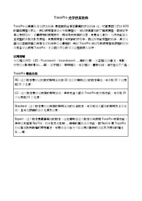
TracePro光学仿真软件TracePro这套高阶光学仿真软件,是目前市占有率最高的仿真软件,这一切都是因为它以ACIS 的固体模型为核心,所以使用者在设计分析模型时,可以非常直观的了解其模型。
而在赋予其对象材质时,不需特殊的使用技巧,即可完成所有的设定,更是令人激赏。
当然功能强大且完整的分析图形及表格,更是使用者不可或缺的好帮手。
而这样功能完整的软件,其学习曲线却目前市面上所有光学软件中公认最短的,所以TracePro可以帮助使用者在很短的时间内完全学会使用TracePro,不会因为冗长的学习过程而使人却步。
应用领域车灯相关(HID、LED、Fluorescent、Incandescent……等的灯源)、太空相关(杂散光、鬼影、热效应对影像的影响……等)、显示相关、照明相关、生医相关、雷射组件、消费性电子产品、TracePro等级分类RC:这个版本是针对反射式照明系统在3D设计环境所设计的版本等级,可分析35个对象和10个光源。
LC:这个版本是针对所有的照明系统,其中包含大部分TracePro的分析功能,可分析35个对象和10个光源。
Standard:这个版本是针对所有的照明系统的标准版本,可分析绝大部分的照明及光学系统,且可无限制的设计光源及对象。
Expert:这个版本是最高等级的版本,这也意味着这个版本将可使用TracePro所有功能,其中还包括有RepTile、热分析及双折射……等等的高阶设计功能。
而Reptile是TracePro针对背光板所新增的特殊算法,可用来设计百万个以上用来散射的点以及多棱镜的增光片……等。
汽车产业车灯设计方案(TracePro in the automobile industry lamp)Design Overview汽车产业车灯设计方案利用TracePro强大的分析运算及简易的操作接口,准确的设计出符合国际法规要求的车灯系统。
更可搭配外挂模块-Photo-realistic Rendering秀出人眼的实际视觉效果。
tracepro实验报告范文以下是一份TracePro实验报告的范文,供参考:实验报告标题:利用TracePro进行光学系统设计和分析实验目的:通过使用TracePro软件,了解和掌握光学系统设计和分析的基本原理和方法。
实验器材:个人电脑、TracePro软件实验原理:TracePro是一款专业的光学系统设计和分析软件,可以模拟和优化光线在光学系统中的传播和损失情况。
它使用光线追迹算法,通过设置光源、光学元件和检测器等参数,可以模拟出光线在光学系统中的传播路径和特性,如光线的强度分布、光程差、偏振亮度、折射率等。
实验步骤:1. 打开TracePro软件,新建一个光学系统。
2. 设置光源参数,如光源类型、功率、发射波长等。
3. 设置光学元件参数,如透镜的曲率半径、折射率、直径等。
4. 设置检测器参数,如检测器的位置、尺寸等。
5. 运行光线追迹算法,模拟光线在光学系统中的传播路径和特性。
6. 分析光线的强度分布、光程差、偏振亮度等参数。
7. 根据分析结果,优化光学系统设计参数。
实验结果:通过TracePro软件模拟光学系统的传播路径和特性。
得到了光线的强度分布图、光程差曲线和偏振分布图等结果。
根据分析结果,可以优化光学系统设计参数,如改变透镜的曲率半径、调整光源的位置等,以达到更好的光学性能。
结论:TracePro是一款功能强大的光学系统设计和分析软件,可以模拟和优化光学系统中光线的传播和特性。
通过TracePro的使用,可以了解和掌握光学系统设计和分析的基本原理和方法,并优化光学系统设计参数,以实现更好的光学性能。
参考文献:[1] TracePro, Lambda Research Corporation, 2021.注意:此范文仅供参考,请根据具体实验内容和要求进行修改和补充。
tracepro使用指南TracePro是一款用于光学和照明系统设计和分析的软件工具。
它具有强大的功能和灵活性,可以帮助用户快速准确地进行光学系统的设计和优化。
本文将为您介绍TracePro的使用指南,帮助您更好地了解和使用这一软件工具。
一、TracePro简介TracePro是美国Lambda Research公司开发的一款基于物理光学原理的软件工具。
它提供了一套完整的工具和功能,可以帮助用户进行光学系统的设计、分析和优化。
TracePro可以模拟和分析多种光学过程,包括散射、透射、反射、折射等。
它可以模拟光线的传播路径,并计算光学元件的性能参数,如光强分布、亮度、照度等。
二、TracePro的安装与启动2. 启动TracePro:启动TracePro后,可以选择新建一个项目或者打开一个已有的项目。
新建项目时,需要先选择一个工作目录和文件名,并设置项目的基本信息。
三、创建模型1. 创建模型:在TracePro中,可以通过两种方式创建模型,即创建几何模型和导入CAD文件。
创建几何模型时,可以选择从零开始创建或者使用预定义的几何体。
导入CAD文件时,可以选择支持的CAD文件格式,如STEP、IGES等。
2. 定义材料属性:在创建模型后,需要为模型定义材料属性。
可以从TracePro的数据库中选择预定义的材料属性,也可以手动定义或导入材料属性。
3.修改模型参数:可以对模型的参数进行修改,如几何体的大小、形状等。
也可以对模型的材料属性进行修改,如折射率、吸收率等。
四、设置光源和探测器1. 设置光源:在TracePro中,可以选择不同类型的光源,如点光源、平行光源、球面光源等。
可以设置光源的功率、波长、方向等参数。
2. 设置探测器:在TracePro中,可以选择不同类型的探测器,如粒子探测器、能量探测器、光强度探测器等。
可以设置探测器的位置、形状、大小等参数。
五、设置系统条件1. 设置边界条件:在TracePro中,可以设置系统的边界条件,如外部介质的折射率、吸收率等。
Tracepro学习教程Tracepro是一款强大的光学设计和仿真软件,广泛应用于光学系统设计和光学元件性能评估。
它提供了一套完整的工具和功能,可用于光学元件分析、衍射和散射分析、非球面镜设计、光学系统优化、发光二极管(LED)设计和非线性光学分析等。
1. Tracepro的安装和基本界面2. Tracepro的基本操作和数据输入在学习Tracepro之前,用户需要了解软件的基本操作和数据输入方式。
Tracepro可以通过输入光源、光学元件和材料等数据来进行光学设计和分析。
用户可以使用Tracepro提供的标准光源模型,也可以导入外部光源数据。
通过设置光源的参数和位置,用户可以模拟不同类型的光源,并观察其在光学系统中的传播和衍射情况。
对于光学元件的设计,用户可以选择使用Tracepro提供的标准元件模型,也可以自定义非球面镜、透镜等元件。
用户可以设置元件的参数和材料属性,并观察它们对光学系统的影响。
3.光学系统设计和优化Tracepro提供了丰富的工具和功能,用于光学系统设计和优化。
用户可以通过在光学系统中添加、删除或调整光学元件,来改变光学系统的传输特性。
用户可以观察光束的传播路径、聚焦性能和光线散射情况,以评估光学系统的性能。
在光学系统优化方面,Tracepro提供了多种优化算法和策略,例如遗传算法、步进法和灵敏度分析等。
用户可以根据需要选择合适的优化方法,并设置优化的目标和约束条件,以实现光学系统的最佳设计。
4.光学元件性能评估和分析5.LED设计和非线性光学分析除了常规光学设计和分析,Tracepro还提供了专门的功能和工具,用于发光二极管(LED)设计和非线性光学分析。
在LED设计方面,用户可以模拟LED光源的发射特性、发光度和色温等,并评估其在光学系统中的光衰情况。
在非线性光学分析方面,Tracepro可以模拟非线性光学效应,例如二次谐波生成(SHG)、三次谐波生成(THG)和光学放大等。
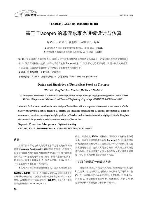
10.16638/ki.1671-7988.2020.13.028基于Tracepro的菲涅尔聚光透镜设计与仿真吴贺利1,杨帆2,罗晨晖2,柯婉頔2,吴满2(1.武汉外语外事职业学院机电技术学部,湖北武汉436500;2.武汉科技大学城市学院机电工程学部,湖北武汉436500)摘要:文章通过对太阳能聚光光伏发电研究中重要的聚光器菲涅尔透镜基本设计,完成太阳光的光谱数据提取与模拟、聚光器材料性能建模,并在光学仿真软件Tracepro中进行太阳光聚光光迹模拟追踪,实现太阳光光路仿真,并完成菲涅尔聚光透镜的结构设计分析以及其聚光光斑特性分析。
关键词:菲涅尔透镜;太阳光谱;光迹追踪中图分类号:P182.3 文献标识码:A 文章编号:1671-7988(2020)13-90-03Design and Simulation of Fresnel lens based on TraceproWu Heli1, Yang Fan2, Luo Chenhui2, Ke Wandi2, Wu Man2(1.Department of mechanical and electrical technology, Wuhan college of foreign language & foreign affairs, Hubei Wuhan 436500; 2.Department of Mechanical and Electrical Engineering, City college of WUST, Hubei Wuhan 436500)Abstract:In this paper, based on the basic design of Fresnel lens which is important concentrator in the research of solar photovoltaic power generation, complete the spectral data simulation of sunlight and the material performance modeling of concentrator, simulation tracking of sunlight spotlight in TracePro, realize the simulation of sunlight path, finally, Complete the structural design analysis and characteristic analysis of Fresnel lens.Keywords: Fresnel lens; Solar spectrum; Light trail trackingCLC NO.: P182.3 Document Code: A Article ID: 1671-7988(2020)13-90-03前言应用于高倍聚光光伏发电的菲涅尔聚光透镜是由法国物理学家Augustin Jean Fresnel在1822年所发明的一种透镜[1],由多个同轴排列或平行排列的棱镜所形成的一序列不连续曲面取代了一般透镜的连续球面,因此,菲涅尔透镜结构简单,便于制造,在重量和体积上比一般透镜更轻、更薄,在设计上可以获得更大的孔径与焦距比[2]。


光学工程师和结构工程师高度协同合作的光学模拟设计分析软件TracePro TracePro是美国Lambda Research公司开发的一款光学模拟设计分析软件。
它是世界上第一款以ACIS内核的光学软件,历经25年的不断发展,已成为全球知名的光学软件,并多次荣获软件设计大奖。
它具有相当高的准确性,简易的操作接口及很短的学习曲线。
其应用涵盖了当今能涉及光学产业的众多领域。
与CAD软件搭建有效平台光学系统的设计,公差分析和精度等的要求需要光学工程师和结构工程师高度协同合作。
设计团队要面对越来越短的研发周期和更低的研发预算。
为了有效管理协调合作流程,TracePro不仅要方便光学工程师使用,同时还要能让整个设计流程中其他部门的工程师使用。
图片来自:张智鸿博士TracePro对档案的共享是双向的。
一个复杂结构的系统模型可以通过不同的CAD软件如Pro-E、Solidworks,UG,Catia等画好后,直接读入TracePro进行光学分析,读取后的模型是实体的,不仅仅是面和线,从而保证CAD模型的完整性。
TracePro Rayviz For SolidWorksRayViz 作为 SolidWorks 的一个扩展插件,不仅可以在 SolidWorks 工作环境中直接定义和保存模型光学属性,而且还可以在该 CAD 工作环境中直接进行光线追迹。
通过 RayViz, 把 TracePro 和 Solidworks 链接了起来,一个模型可以在 TracePro 中用于光学计算和分析,也可以在 Solidworks 中进行机械设计并应用光学属性。
RayViz 在 Soldiworks 中增加光线追迹功能以便于进行初步的模型验证、光线走向和光路分析。
该插件界面简洁,易学易用,灯具结构工程师也方便快捷掌握,可明显缩短产品设计周期20—50%,并提高产品品质。

Tracepro实例学习教程TracePro是一个强大的光学仿真软件,可以帮助工程师和科学家设计和分析光学系统。
本教程将介绍TracePro的基本操作和主要功能。
通过几个实例案例,你将学会如何使用TracePro进行光线追踪、光线分析和优化等。
实例一:透镜系统设计假设我们要设计一个简单的透镜系统,主要包括一个凸透镜和一个凹透镜。
我们首先打开TracePro,创建一个新的项目,并选择“凸透镜”和“凹透镜”作为初始模型。
然后,我们可以设置透镜的物理属性,如曲率半径、折射率等。
接下来,我们需要定义光源。
在TracePro中,我们可以选择不同类型的光源,如点光源、方向光源等。
我们可以通过拖动光源调整其位置和方向,以模拟实际情况。
在设置完透镜和光源后,我们需要设置接收器,即检测光线的位置。
可以选择光强、光通量、光能量等作为接收器参数。
通过选择不同的接收器参数,可以得到不同的光学性能结果。
最后,我们可以通过点击“分析”按钮开始光线追踪。
TracePro会模拟光线在透镜系统中的传播和折射,然后显示光强分布、光通量等结果。
我们可以通过对比不同参数设置下的结果,来优化透镜系统的设计。
实例二:光学元件分析在这个实例中,我们将学习如何使用TracePro对光学元件进行性能分析。
假设我们使用一个平面反射镜作为光路中的一个元件。
我们打开TracePro,创建一个新的项目,并选择“平面反射镜”作为初始模型。
首先,我们需要设置反射镜的物理属性,如尺寸、反射率等。
然后,我们选择一个合适的光源,并设置接收器。
在设置完光源和接收器后,我们可以通过点击“分析”按钮开始光线追踪。
TracePro会模拟光线在反射镜上的反射,然后显示反射效果、光强分布等结果。
我们可以通过对比不同参数设置下的结果,来优化反射镜的设计。
实例三:光学系统优化在这个实例中,我们将学习如何使用TracePro对光学系统进行优化。
假设我们有一个复杂的光学系统,包括多个透镜、反射镜、棱镜等。
LED(Tracepro官⽅LED建模光学仿真设计教程)RequirementsModels: None Properties: NoneEditions: TracePro LC, Standard and ExpertIntroductionIn this example you will build a source model for a Siemens LWT676 surface mount LED based on the manufacturer’s data sheet. The dimensions will be used to build a solid model and the source output will be defined to match the LED photometric curve.Copyright ? 2013 Lambda Research Corporation.Create a Thin SheetFirst analyze the package to determine the best method of constructing the geometry in TracePro. The symmetry of the package suggests starting from a Thin Sheet and extruding the top and bottom halves with a small draft angle. Construct Thin Sheet in the XY plane.1. Start TracePro2. Select View|Profiles|XY or click the View XY button on the toolbar, and switch to silhouette mode, View|Silhouette.3. Select Insert|Primitive Solid and select the Thin Sheet tab.4. Enter the four corners of the Thin Sheet in mm in the dialog box, as shown below, and click Insert.5. Click the Zoom All button or select View|Zoom|All to see the new object.Selecting a SurfaceTracePro uses surface and object selections for many operations.1. Close the Insert Primitive Solid dialog box. The thin sheet object has only one surface.2. Select View|Profiles|YZ or click the View YZ button on the toolbar to view the profile of the Thin Sheet.3. Select the surface using by selecting Edit|Select|Surface (or clicking the Select Surface button), then use the mouse to “pick” the rod end, which is Surface 0 as shown in the figure below, After selecting the surface it will be highlighted in black in the model view.Use Sweep to Form a SolidThe package has a small angle of about 4 degrees so you will extrude the sheet using Edit|Surface|Sweep.1. Select Edit|Surface|Sweep or right-click on the surface and select Sweep.2. Enter a sweep distance of 0.9 mm and a draft angle of 4 degrees.3. Click Apply. The surface will be swept along the plane’s surface normal, in this case along the Z axis.4. Make sure Surface 4 is selected for the next sweep to complete the object.Complete the SolidPerform two more sweep operations to complete the solid according to the data sheet.1. Select Surface 4.2. Sweep by 0.2 with draft=0 to create the central portion of the package.3. Select Surface 8.4. Sweep again by 0.9 with a –4 degree draft to complete the construction.Create a Conical HoleNext you can add the cone reflector which holds the LED die. To create the conical hole, first create a cone, then perform a Boolean Subtract operation.1. Select Insert|Primitive Solid and select the Cylinder/Cone tab.2. Select the Cone option and enter the values shown, then click Insert to create the cone.Subtract the Cone from the PackageBoolean Operations use a concept of Body and Tools. The Body is the item you wish to keep and the tools are items which will have some effect on the Body. Here you want to remove the volume occupied by the cone from the package. In this example the Body is the package and the Tool is the cone.1. Select the Package object from the System Tree by clicking on the Thin sheet 1 object.2. Select the Cone 1 object from the System Tree using Ctrl+Click to add it to the selection.3. Select Edit|Boolean|Subtract or use the Boolean Subtract button as shown in the figure.4. Cone 1 will be removed from the System Tree as shown in the bottom figure with 15 surfaces shown in the Thin Sheet ObjectYou also need to add a diffuser. This will be a thin cylinder joined to the package. You will make the inner surface of the diffuser scattering and the inside of the cone a perfect mirror.1. Select Insert|Primitive Solid, Cylinder/C one tab.2. Enter the values shown, Major Radius 1.2, Length .01 and Base Position 1.99.3. Click Insert to create the cylinder.Now you will add the LED chip itself. The dimensions are not given, but you can estimate from the data sheet that it is 0.4 x 0.4 x0.15 mm.1. From the Insert|Primitive Solid dialog box, select the Block tab2. Enter the values shown in the Block dialog shown below. Make sure you name the object by typing LED in the Name box3. The center of the LED has a Z-value 1.175 to position the block so that it is on the bottom of the conical hole.4. Click Insert to create the block.5. The other 2 objects could have been named when they were created, but they can also be renamed at any time. Selecteach object in turn with 2 slow clicks to get the name in edit mode, then name them “Package”, and “Diffuser”.Diffusing Surface PropertyYou will make three assumptions about the optical properties of this LED package. First, that the Diffuser is a perfect Lambertian transmitter with no losses. Second, the inside of the conical hole is a perfect reflector without any losses. Third, the LED is a perfect reflective diffuser. These simple-minded assumptions could be improved with more data from the manufacturer.1. TracePro includes a Perfect Mirror Surface Property so you only need to add the diffuser property.2. Select Define|Edit Property Data|Surface Properties.3. Click the Add Property button, enter the property name Lambertian Diffuser, select ABg for the Scatter Model, andclick the OK button to enter data into the surface property editor spreadsheet.4. Set the absorptance value to 0.0 (a lossless surface) and select Solve for BTDF (Bidirectional Transmission DistributionFunction) from the drop-down list. The BTDF is the scattering portion of the surface property with three coefficients.(See the TracePro User’s Manual for information about the ABg scattering model). Make sure you save the property by either clicking on the Save button or selecting File|Save. You should see the completion message that the property was saved successfully as shown in the figure below.Make the inside surface of the Diffuser the scattering surface.1. Select Define|Apply Properties to open the Apply Properties dialog box and select the Surface option from the list onthe left.2. Select the inner surface of the Diffuser by either:clicking on it in the System TreeSelecting Edit|Select|Surface and clicking on the surface in the model window.3. You may want to zoom in on the diffuser to see which surface is which (as shown).4. Select Lambertian Diffuser from the Surface Property Name dropdown list.5. Click Apply to apply the property to the diffuser.The next step is to apply a mirror surface property to the base and sides of the conical hole in the package.1. Select the Package object and select surfaces 0 and1. After selecting one surface, you can add to the selection by holding down the Ctrl key and selecting additional surfaces.2. Select Perfect Mirror from the Surface Property Name drop-down list.3. Click Apply to apply the property to the selected surfaces.Define LED Source1. Select Raytrace|Raytrace Options to open the Raytrace Options dialog box.2. On the Options tab, select Photometric for the Analysis Units type.3. Click Apply and close the dialog box.4. Select the top surface of the LED (surface 0).5. In the Apply Properties dialog box, select the Surface Source menu item.6. Enter the values and selections shown, 50000 rays, .54 microns7. Click Apply to create an LED that emits 0.05 lumens in a Lambertian patternPerform the RaytraceNow the model is ready for raytracing.1. Begin a ray-trace by:Raytrace|Trace RaysselectingTracePro will perform an Audit of the model and report any invalid properties or geometry, and then the ray-trace will start.Candela Plot Options1. Select Analysis|Candela Options.2. Select the Orientation and Rays tabs.3. Set the Normal and Up vectors as shown in the top illustration.4. Select the Candela Distributions tab and enter the settings shown in the bottom illustration.5. Click Apply to apply the changes to the plot.Display Candela PlotThe candela plot from TracePro can be compared to the photometric curve from the data sheet. 1. Select Analysis|Candela Plots|Polar Candela Distribution or press the Polar Candela Distribution button. 2. Compare the data from the datasheet with TracePro’s results.。
Chengdu(中国玻璃库)Baf3 钡火石玻璃Coating(保护层;涂层)AL203 氧化铝ALF3 氟化铝Bi203 三氧化二铋性状:黄色重质粉末CeF3 氟化铈(晶体)ciromirxHfF4 PbF2和LiF能增大玻璃的折射率,SrF和HfF4能降低玻璃的折射率HF02 氧化物:Zr02、A1203、Hf02、Th02HF02 氟化镁氟化镁【用途】用于制造陶瓷、玻璃;冶金镁金属的助熔剂;光学仪器中镜头和滤光器的涂层;阴极射线屏的荧光材料;焊剂等。
Sc203Si0 硅Si02 纯二氧化硅二氧化硅性质:SiO2又称硅石,如石英、石英砂等ta205 钽Ti02 具有优异的紫外线屏蔽性,再加上它的透明性Ai02 氧化铝的熔点很高(2800摄氏度),用来制造防火材料ZnS 【硫化锌】化学式ZnS,式量97.43。
白色或微黄色粉末。
α变体为无色六方晶体,密度3.98克/厘米3,熔点1700±28℃(202.66千帕——20大气压);β变体为无色立方晶体,密度4.102克/厘米3,于1020℃转化为α型。
不溶于水、易溶于酸。
见阳光色变暗。
久置潮湿空气中转变为硫酸锌。
若在晶体ZnS 中加入微量的Cu、Mn、Ag做活化剂,经光照后,能发出不同颜色的荧光。
用作分析试剂、涂料、制油漆、白色和不透明玻璃,充填橡胶、塑料,以及用于制备荧光粉。
由硫跟锌共热制得。
Zr02 高温结构强度高,1000℃时耐压强度可达1200~1400MPa。
导电性好Corning(康宁公司是特殊玻璃和陶瓷材料的全球领导厂商,航天飞机创造玻璃窗户)Glass(玻璃)Fused Silica 装有保险丝的/二氧化硅Pyrex 耐热玻璃Zerodur 微晶玻璃Hikari(是光的意思<日本>玻璃材料)BAF10 熔断器保险丝BAF系列BAF11E-BK7 光学玻璃E-F16 绝热吸声材料E-FK01 无色光学玻璃E-K3 无色光学玻璃E-KF6 光学玻璃E-LAF 光学玻璃E-LAK 光学玻璃E-LLF1 国内望远镜生产工厂分布和望远镜渠道E-SK11 无色光学玻璃SK9 弹簧钢HOYA(豪雅)ADC1 铝锭BACD11 光学玻璃BAF11 中国新华光(光学玻璃)LF5 防锈铝FD8 光学玻璃IR_Materials(红外材料)Liquids(液体)MTI(活动目标指示器)Plastic(塑料)Tissue(组织)Vitron(德国Vitron 公司远红外光学玻璃、晶体)(注:文档可能无法思考全面,请浏览后下载,供参考。
tracepro仿真设计实例三、实验步骤下面以导光管为例:1.运行Tracepro并用File|New打开一个新模型;2.打开Insert|Primative Solid对话框,并选择Cylinder/Cone标签;3.输入主半径为2,长度为30,并按下Insert按钮;4.按下Zoom All缩放全部或者View|菜单以便看到新物件5.用Edit|Select|Surface菜单选择棒的右端面right end;用鼠标“选取”棒的端面。
6.选择Edit|Surface|Revolve Surface Selection旋转填料选项;7.输入角度90°与弯曲半径25;8.将轴置于点(0,-25,30),并定义轴的指向为空间中的X轴方向;9.按下旋转填料Revolve Surface按钮来进行弯曲;10.通过Edit|Surface|Sweep打开表面拉伸填料选项Sweep Surface Selection对话框;11.在拉伸长度Distance框中输入15,拉伸角度Draft angle为-2°,表面沿着设定长度被拉伸的同时,以2°的角度逐渐变细:12.用Edit|Select|Object菜单选择导光管,并用鼠标点击导光管;13.用Define|Apply Properties(设定材料),打开Apply Properties应用特性对话框:14.选择Plastic目录Catalog,选择名称Acrylic并按下Apply按钮;15.选择菜单Insert|Lens Element,透镜参数为Surface1 Radius : 25,Thickness 3.5mm,Material BK7,Position (0, 0, -40)在导光管前安置一汇聚透镜,以达到较好的光路耦合性能。
16.设定光源,菜单选择,Analysis|Grid Raytrace,网格光线沿圆周排列Annular,半径Outer Radius 10mm,网格光线圆周数量Rings : 10,光线的起点位置 (0, 0, -48).四、仿真结果按下各点光源Grid Raytrace对话框中的Apply&Trace Rays按钮,进行光线追迹。
基于TracePro的光学仿真实验教学唐小村(淮海工学院理学院,江苏连云港 222005)摘 要:阐述了将光学设计软件应用到实验教学中的意义与可行性。
利用TracePro模拟设计了偏振光分离和转换的实验光路,可以通过变换光路中的条件和参数,获得各种偏振状态的光线。
专业光学仿真设计软件的引入,为仿真实验教学开辟了新的途径,对于光学仿真实验教学的进一步研究具有参考价值。
关键词:TracePro;仿真实验;偏振光中图分类号:O435.1 文献标志码:A 文章编号:1002-4956(2013)01-0094-03Simulation experimental teaching of optics based on TraceProTang Xiaocun(School of Science,Huaihai Institute of Technology,Lianyungang 222005,China)Abstract:The meaning and feasibility of the optical design software applications to the experimental teachingare discussed.Using TracePro software,the experimental optical path of the polarized light separation andconversion is simulated.By changing the conditions and parameters in the optical path,a variety of polarizationstates of light can be obtained.The introduction of professional optical simulation design software has openedup new avenues for the simulation teaching,which has reference value in the further study for simulation ex-perimental teaching of optics.Key words:TracePro;simulation experiment;polarized light收稿日期:2012-04-13作者简介:唐小村(1976—),男,江西宜春,本科,实验师,主要从事实验室教学与管理工作.E-mail:tangxc76@163.com 在光学实验教学中,计算机的数值仿真技术已经得到广泛应用,光学仿真实验能够将抽象、难懂的光学概念和规律通过仿真界面,以图像的形式进行描述。
TraceProTracePro是一套普遍用于照明系统、光学分析、辐射度分析及光度分析的光线模拟软体。
它是第一套以ACIS solid modeling kernel为基本的光学软体。
第一套结合真实固体模型、强大光学分析功能、资料转换能力强及易上手的使用介面的模拟软体。
TracePro可利用在显示器产业上,它能模仿所有类型的显示系统,从背光系统,到前光、光管、光纤、显示面板和LCD投影系统。
比起传统的原形方法,TracePro在建立显示系统的原型时,在时间上和成本上要降低30-50%。
应用领域包括:照明、导光管、背光模组、薄膜光学、光机设计、投影系统、杂散光、雷射邦浦常建立的模型:照明系统、灯具及固定照明、汽车照明系统(前头灯、尾灯、内部及仪表照明)、望远镜、照相机系统、红外线成像系统、遥感系统、光谱仪、导光管、积光球、投影系统、背光板。
TracePro作为下一代偏离光线分析软件,需要对光线进行有效和准确地分析。
为了达到这些目标,TracePro具备以下这些功能:处理复杂几何的能力,以定义和跟踪数百万条光线;图形显示、可视化操作以及提供3D实体模型的数据库;导入和导出主流CAD软件和镜头设计软件的数据格式。
在使用上,TracePro使用十分简单,即使是新手也可以很快学会。
TracePro使用上只要分5步:1、建立几何模型;2、设置光学材质;3、定义光源参数;4、进行光线追迹;5、分析模拟结果。
其实原则上来讲,此次的TracePro大版本的更新在功能增强上的增加并不是特别突出,现在更多用户的更加需要的是能够进行Auto Design的优化功能。
TracePro的优化功能是基于自身的Macro语言的,而其Scheme 语言的功能很强大,可是对于用户而言,尤其是初学者而言非常苦涩难懂。
针对这样的现状,TracePro中文站已经解决了包括效率优化、准直优化、均匀照明优化的常用优化的自主开发。
让用户可以方便的进行优化设计。