LED(Tracepro官方LED建模光学仿真设计教程)
- 格式:pdf
- 大小:1.25 MB
- 文档页数:16
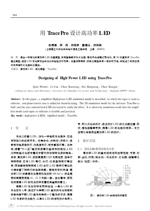
用T racePro设计高功率L ED钱雯磊,李 筠,陈晓荣,戴曙光,陈祥熙(上海理工大学光学与电子信息工程学院 上海 200093)摘 要:提出一种简化的高功率L ED仿真模型,采用圆锥面作为反光碗,增加平凸透镜汇聚光线,用3D仿真软件TracePro 建立模型,追迹L ED发光面发出的光线并检验设计效果。
仿真结果表明,该简化模型具有一定的可行性,并验证了实际应用中采用锥形反光碗的合理性。
关键词:高功率L ED;简化模型;TraceProDesigning of High2Pow er L ED using T raceProQian Wenlei,Li J un,Chen Xiaorong,Dai Shuguang,Chen Xiangxi (College of O ptics and Elect ronics,Universit y of S hanghai f or S cience and Techno log y,S hanghai200093,China)Abstract:In t his paper,a simplified High2power L ED simulation model is described,in which t he taper is used as reflector,and plane2convex lens is added for beam2focusing.The3D simulation model by t he software TracePro is built and the rays emitted from L ED are traced to verify t he effect.It is shown by simulation result t hat t he simpli2 fied model used taper as reflector is feasible and practical.K ey w ords:high2power L EDS;implified model;TracePro1 引 言发光二极管(L ED),作为一种电致发光器件,已经有较悠久的应用历史。

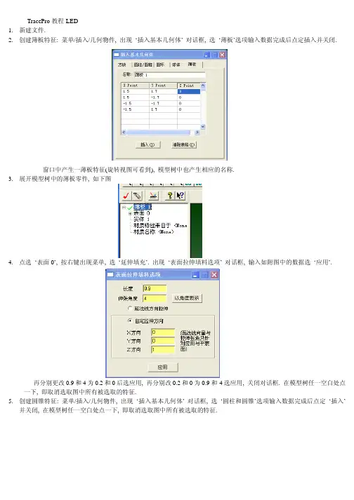
TracePro教程-LED1.新建文件.2.创建簿板特征: 菜单/插入/几何物件, 出现‘插入基本几何体’ 对话框, 选‘薄板’选项输入数据完成后点定插入并关闭.窗口中产生一薄板特征(旋转视图可看到), 模型树中也产生相应的名称.3.展开模型树中的薄板零件, 如下图4.点选‘表面0’, 按右键出现菜单, 选‘延伸填充’. 出现‘表面拉伸填料选项’ 对话框, 输入如附图中的数据选‘应用’.再分别更改0.9和4为0.2和0后选应用, 再分别改0.2和0为0.9和-4选应用, 关闭对话框. 在模型树任一空白处点一下, 即取消选取图中所有被选取的特征.5.创建圆锥特征: 菜单/插入/几何物件, 出现‘插入基本几何体’ 对话框, 选‘圆柱和圆锥’选项输入数据完成后点定‘插入’并关闭, 在模型树任一空白处点一下, 即取消选取图中所有被选取的特征.6.进行布尔运算: 在模型树中先选‘薄板 1’, 再按住Ctrl键选‘圆锥 1’. 菜单/编辑/布林运算/差集.7.慢速点选模型树中‘薄板 1’ 两次, 改名为 ‘Package’. 在模型树任一空白处点一下, 即取消选取图中所有被选取的特征.8.创建圆柱特征做散光板: 菜单/插入/几何物件, 出现‘插入基本几何体’ 对话框, 选‘圆柱和圆锥’选项输入数据完成后点‘插入’ 并关闭. 在模型树任一空白处点一下, 即取消选取图中所有被选取的特征.9.创建方块特征做LED: 菜单/插入/几何物件, 出现‘插入基本几何体’ 对话框, 选‘方块’选项输入数据完成后点‘插入’ 并关闭. 在模型树任一空白处点一下, 即取消选取图中所有被选取的特征.10.关键的来了, 设置三部曲:首先, 在模型树选取散光板特征(不是选展开后的某一面), 定义散光板的材质属性, 菜单/定义/编辑材质/表面材质, 出现对话框, 左侧选‘新增特性’ 按钮, 又出现‘输入一个新的表面特性’ 对话框, 如图设置并确定.然后, 将‘吸收率’ 设置为0, 将‘求解’ 设置为 BTDF, 按保存, 如下图:会自出现 ‘BTDF 符合能量守恒’ 的提示, 按确定后关闭, 再关闭‘表面材质编辑器’ 对话框.选择模型树中的 ‘Diffuser’按右边加号展开, 选择‘表面 1’, 也就是散光板的内侧, 然后按右键, 选菜单中的‘属性’,出现‘应用特性’对话框, 按下图设置后按‘应用’ 并关闭.12.第三步设置 ‘Package’ 上的凹槽的面属性.选择模型树中的 ‘Package’按右边加号展开, 选择‘表面0和表面 1’, 也就是凹槽的底面和侧面, 然后按右键, 选菜单中的‘属性’, 出现‘应用特性’对话框, 按下图设置后按‘应用’ 并关闭. 在模型树任一空白处点一下, 即取消选取图中所有被选取的特征.13.菜单/分析/光线追迹选项, 出现‘光线追迹选项’ 对话框, 照下图输入内容后‘应用/关闭’.14.设置LED光源:选择模型树中LED展开, 选择‘表面 0’ 即LED上表面, 右键出‘应用特性’ 对话框, 设置表面光源后按‘应用/关闭’.15.一切模型都设置完必, 就待分析了.16.菜单/开始光线追踪, 出现‘光线追踪’对话框, 选择追迹光线按钮/应用/关闭.17.菜单/分析/Candela Plots选项, 出现 ‘Candela选项’ 对话框, 选‘方位与光线’选项, 输入数据/应用.再选Candela 分布选项, 输入数据/应用/关闭.18.菜单/分析/Candela Plots/Polar Candela Distribution.。
TracePro实例教程第一步是创建一个新项目。
在启动TracePro后,点击“File”菜单中的“New”选项,然后选择“Project”命令。
在弹出的对话框中,输入项目的名称和路径,并选择模板。
我们选择“General”模板,它提供了一个基础的空白项目。
第二步是设置光线追迹的参数。
在项目创建后,我们需要设置光线追迹的参数,以便进行模拟和分析。
在左侧的“Configuration tree”窗口中,选择“Model”节点,并点击右键,在弹出菜单中选择“Add Model”。
在弹出的对话框中,选择“Ray Trace”模块,并点击“OK”按钮。
然后,在右侧的属性窗口中,设置光线源的类型和位置,以及其他相关参数。
第三步是绘制光学系统。
在项目中,我们需要绘制光学系统的几何形状。
在左侧的“Configuration tree”窗口中,选择“Geometry”节点,并点击右键,在弹出菜单中选择“Add Surface”。
然后,在右侧的属性窗口中,设置表面的类型和位置,例如球面、棱镜等。
通过重复这个过程,我们可以添加多个表面来构建完整的光学系统。
第四步是定义材料属性。
在光学系统设计中,材料的光学特性非常重要。
在左侧的“Configuration tree”窗口中,选择“Materials”节点,并点击右键,在弹出菜单中选择“Add Material”。
然后,在右侧的属性窗口中,设置材料的光学参数,例如折射率、透射率等。
第五步是设置分析和输出参数。
在光学系统设计完成后,我们可以通过模拟和分析来评估其性能。
在左侧的“Configuration tree”窗口中,选择“Analysis”节点,并点击右键,在弹出菜单中选择“Add OutputAnalysis”。
然后,在右侧的属性窗口中,选择要分析的参数和结果的输出格式。
第六步是运行模拟和分析。
在完成了上述的设置后,我们可以点击“Run”按钮来运行模拟和分析。
TracePro将根据设置的参数进行光线追迹,并生成相应的结果。

如何使用TracePro模拟LED光源效果使用的TracePro版本是3.3.7实验目的:36颗LED环形排列,调整环形的半径和光源平面与物体的距离,观察何种光源参数比较合适实验步骤:1. 在YZ平面上建立初始面片Thin Sheet,使用坐标参数如下:(0,1,1)(0,1,-1)(0,-1,-1)(0,-1,1)2. 将这个面片Move(30,0,0)3. 设置其Surface Source为如下参数:Flux, 1 Watts, Total 10,0004. 将其Rotate ,以10度为间隔,About Z ,点击35次copy 生成总共36颗环形排列的LEDS U M E C O L L E C T I O N5. 插入一个受光物体,Insert Primitive Solids,使用Cylinder/Cone,采用参数为:Major 25(表示直径25mm),Base Position (0,0,-5)6. 点击Source Trace生成追踪光线7. 选择受光物体,选择受光面,选择菜单“Select Surface”,在“%Starting Rays to Display”中填写“1”,这样只显示1% 的光线,避免显示太多看不清楚8. 选择菜单“Analysis / Irradiance Map Options”,设置辉度图/照度图的选项,在“Ray to Plot”中选择“incident”即针对入射光线进行分析9. 然后选择“Analysis / Irradiance Map”即可显示辉度图/照度S U M E C O L L E CT I O N}360,000根光线总计运行时间约23秒实验环境:CPU:Pentium M 1.3GHz内存:512+256 MBsume@20100905S U M E C OL L E CT I O N。


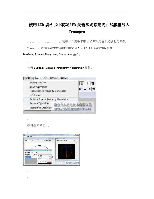
使用LED规格书中获取LED光谱和光强配光曲线模型导入Tracepro,,,,,,,,,,,,,,,,,,,,,,,使用LED规格书中获取LED光谱和光强配光曲线, TracePro,表面光源生成器的使用实例1-获取LED光谱数据,打开Surface,Source,Property,Generator插件,,打开Surface,Source,Property,Generator插件。
,,,,插件整体界面。
,,,,首先,我们需要获取LED的光谱特性数据。
针对XP-G型号的光源,我们以5000K~8300K为例。
,光谱曲线导入方法,,从规格书中获取蓝色曲线为其光谱图。
,,,,将此图片复制并粘贴到插件的波长编辑器中。
点击波长编辑器右下角的helper 按钮展开光谱图形识别窗口。
,,,,光谱曲线定位,,开始进行光谱数据识别前,需要定义两个坐标点,即矩形窗口的左下角及右上角所代表的数据点。
,,点击Set,Ref,1,然后点击矩形窗口左下角即可看到一个蓝色的圈,此点代表波长为,400nm,相对强度为0。
,,将第二坐标修改为对应0.75,和,1。
,,,,点击Set,Ref,2,然后点击矩形窗口右上角即可看到一个蓝色的圈,此点代表波长为,750nm,相对强度为1。
,,开始光谱图形数据识别,,用鼠标连续的在蓝色光谱曲线上取点即可拟合出一条绿色的曲线。
,,为了保证数据准确,必须让绿色曲线和蓝色光谱尽量完全重合,如下图所示:,,光谱数据取样,,完成后,我们一次获得光谱数据。
将右下角的Auto,Sample更改为100,代表我们要获取这条光谱曲线上的100个数据采样。
,,然后点击,Sample按钮,这样我们获得了这100个采用的光谱数据。
,,TracePro,表面光源生成器的使用实例2-获取LED配光曲线,获取光强数据,, ,首先,获取XP-G,LED,5000K~8300K的光强数据-配光曲线。
,,,,我们使用Beam,Shape,Profile,Editer来获取光强数据。

如何使用TracePro模拟LED光源效果使用的TracePro版本是3.3.7实验目的:36颗LED环形排列,调整环形的半径和光源平面与物体的距离,观察何种光源参数比较合适实验步骤:1. 在YZ平面上建立初始面片Thin Sheet,使用坐标参数如下:(0,1,1)(0,1,-1)(0,-1,-1)(0,-1,1)2. 将这个面片Move(30,0,0)3. 设置其Surface Source为如下参数:Flux, 1 Watts, Total 10,0004. 将其Rotate ,以10度为间隔,About Z ,点击35次copy 生成总共36颗环形排列的LEDS U M E C O L L E C T I O N5. 插入一个受光物体,Insert Primitive Solids,使用Cylinder/Cone,采用参数为:Major 25(表示直径25mm),Base Position (0,0,-5)6. 点击Source Trace生成追踪光线7. 选择受光物体,选择受光面,选择菜单“Select Surface”,在“%Starting Rays to Display”中填写“1”,这样只显示1% 的光线,避免显示太多看不清楚8. 选择菜单“Analysis / Irradiance Map Options”,设置辉度图/照度图的选项,在“Ray to Plot”中选择“incident”即针对入射光线进行分析9. 然后选择“Analysis / Irradiance Map”即可显示辉度图/照度S U M E C O L L E CT I O N}360,000根光线总计运行时间约23秒实验环境:CPU:Pentium M 1.3GHz内存:512+256 MBsume@20100905S U M E C OL L E CT I O N。
应用tracepro的LED路灯光学设计光学人生,你的精彩人生!1. 技术背景LED固态半导体照明技术被认为是21世纪的战略节能技术。
中国、欧洲和北美的许多国家和城市都已经进行了LED道路照明技术的开发和大力推广,相比于金属卤素灯(MH)和高压钠灯(HPS),LED路灯拥有更长的寿命(大于5倍);除此之外,LED路灯还具有更好的可控性和光效,可以节能50%之多。
LED路灯的另一个绿色能源的特征是光源本身不含有害物质汞。
光学方面,LED芯片的小光源特性可以比较容易实现精确的配光和二次光学的优化设计,准确控制光线的方向,把光充分的分配到所需要照明的马路上,防止光污染和眩光。
二次光学设计是决定LED路灯的配光曲线、输出光效、均匀度、以及眩光指数的一项重要技术。
现有市场上大部分的高功率白光LED 的光度分布是郎伯分布,光斑是圆形的,峰值光强一半位置处的光束角的全宽度约为120°。
LED路灯如果没有经过二次光学的配光设计,那么照在马路上的光斑会是一个'圆饼',如图1(a)所示,大约1半左右的光斑会散落到马路之外而浪费掉,并且光斑的中间会比较亮,到周围会逐渐变暗。
这种灯装在马路上之后,路灯之间会形成很明显的明暗相间的光斑分布,对司机造成视觉疲劳,引发事故。
这种情况下的LED路灯就不能叫做'节能'和'绿色照明'了。
国家城市道路照明设计标准要求LED路灯的光斑如图 1(b)所示,光斑为长方形,正好可以覆盖马路,并且有很好的均匀性。
LED的二次光学技术,不同于其他的学科,是一门涵盖非成像光学和3维曲面建模的交叉学科,二次光学的设计可以有效解决LED路灯的出光效率、均匀性、配光角度、眩光和安全性等问题,提供符合于国家标准所要求的配光,真正实现环保和绿色的照明。
另外LED路灯有较好的显色指数(CRI),根据需要可以调节不同的色温使其可以满足白天、晚上、晴天和雨天等不同的环境。
RequirementsModels: NoneProperties: NoneEditions: TracePro LC, Standard and ExpertIntroductionIn this example you will build a source model for a Siemens LWT676 surface mount LED based on the manufacturer’s data sheet. The dimensions will be used to build a solid model and the source output will be defined to match the LED photometric curve. Copyright © 2013 Lambda Research Corporation.Create a Thin SheetFirst analyze the package to determine the best method of constructing the geometry in TracePro. The symmetry of the package suggests starting from a Thin Sheet and extruding the top and bottom halves with a small draft angle. Construct Thin Sheet in the XY plane.1. Start TracePro2. Select View|Profiles|XY or click the View XY button on the toolbar, and switch to silhouette mode, View|Silhouette.3. Select Insert|Primitive Solid and select the Thin Sheet tab.4. Enter the four corners of the Thin Sheet in mm in the dialog box, as shown below, and click Insert.5. Click the Zoom All button or select View|Zoom|All to see the new object.Selecting a SurfaceTracePro uses surface and object selections for many operations.1. Close the Insert Primitive Solid dialog box. The thin sheet object has only one surface.2. Select View|Profiles|YZ or click the View YZ button on the toolbar to view the profile of the Thin Sheet.3. Select the surface using by selecting Edit|Select|Surface (or clicking the Select Surface button), then use the mouse to “pick” the rod end, which is Surface 0 as shown in the figure below, After selecting the surface it will be highlighted in black in the model view.Use Sweep to Form a SolidThe package has a small angle of about 4 degrees so you will extrude the sheet using Edit|Surface|Sweep.1. Select Edit|Surface|Sweep or right-click on the surface and select Sweep.2. Enter a sweep distance of 0.9 mm and a draft angle of 4 degrees.3. Click Apply. The surface will be swept along the plane’s surface normal, in this case along the Z axis.4. Make sure Surface 4 is selected for the next sweep to complete the object.Complete the SolidPerform two more sweep operations to complete the solid according to the data sheet.1. Select Surface 4.2. Sweep by 0.2 with draft=0 to create the central portion of the package.3. Select Surface 8.4. Sweep again by 0.9 with a –4 degree draft to complete the construction.Create a Conical HoleNext you can add the cone reflector which holds the LED die. To create the conical hole, first create a cone, then perform a Boolean Subtract operation.1. Select Insert|Primitive Solid and select the Cylinder/Cone tab.2. Select the Cone option and enter the values shown, then click Insert to create the cone.Subtract the Cone from the PackageBoolean Operations use a concept of Body and Tools. The Body is the item you wish to keep and the tools are items which will have some effect on the Body. Here you want to remove the volume occupied by the cone from the package. In this example the Body is the package and the Tool is the cone.1. Select the Package object from the System Tree by clicking on the Thin sheet 1 object.2. Select the Cone 1 object from the System Tree using Ctrl+Click to add it to the selection.3. Select Edit|Boolean|Subtract or use the Boolean Subtract button as shown in the figure.4. Cone 1 will be removed from the System Tree as shown in the bottom figure with 15 surfaces shown in the Thin Sheet ObjectYou also need to add a diffuser. This will be a thin cylinder joined to the package. You will make the inner surface of the diffuser scattering and the inside of the cone a perfect mirror.1. Select Insert|Primitive Solid, Cylinder/C one tab.2. Enter the values shown, Major Radius 1.2, Length .01 and Base Position 1.99.3. Click Insert to create the cylinder.Now you will add the LED chip itself. The dimensions are not given, but you can estimate from the data sheet that it is 0.4 x 0.4 x0.15 mm.1. From the Insert|Primitive Solid dialog box, select the Block tab2. Enter the values shown in the Block dialog shown below. Make sure you name the object by typing LED in the Name box3. The center of the LED has a Z-value 1.175 to position the block so that it is on the bottom of the conical hole.4. Click Insert to create the block.5. The other 2 objects could have been named when they were created, but they can also be renamed at any time. Selecteach object in turn with 2 slow clicks to get the name in edit mode, then name them “Package”, and “Diffuser”.Diffusing Surface PropertyYou will make three assumptions about the optical properties of this LED package. First, that the Diffuser is a perfect Lambertian transmitter with no losses. Second, the inside of the conical hole is a perfect reflector without any losses. Third, the LED is a perfect reflective diffuser. These simple-minded assumptions could be improved with more data from the manufacturer.1. TracePro includes a Perfect Mirror Surface Property so you only need to add the diffuser property.2. Select Define|Edit Property Data|Surface Properties.3. Click the Add Property button, enter the property name Lambertian Diffuser, select ABg for the Scatter Model, andclick the OK button to enter data into the surface property editor spreadsheet.4. Set the absorptance value to 0.0 (a lossless surface) and select Solve for BTDF (Bidirectional Transmission DistributionFunction) from the drop-down list. The BTDF is the scattering portion of the surface property with three coefficients.(See the TracePro User’s Manual for information about the ABg scattering model). Make sure you save the property by either clicking on the Save button or selecting File|Save. You should see the completion message that the property was saved successfully as shown in the figure below.Make the inside surface of the Diffuser the scattering surface.1. Select Define|Apply Properties to open the Apply Properties dialog box and select the Surface option from the list onthe left.2. Select the inner surface of the Diffuser by either:• clicking on it in the System Tree• Selecting Edit|Select|Surface and clicking on the surface in the model window.3. You may want to zoom in on the diffuser to see which surface is which (as shown).4. Select Lambertian Diffuser from the Surface Property Name dropdown list.5. Click Apply to apply the property to the diffuser.The next step is to apply a mirror surface property to the base and sides of the conical hole in the package.1. Select the Package object and select surfaces 0 and1. After selecting one surface, you can add to the selection by holdingdown the Ctrl key and selecting additional surfaces.2. Select Perfect Mirror from the Surface Property Name drop-down list.3. Click Apply to apply the property to the selected surfaces.Define LED Source1. Select Raytrace|Raytrace Options to open the Raytrace Options dialog box.2. On the Options tab, select Photometric for the Analysis Units type.3. Click Apply and close the dialog box.4. Select the top surface of the LED (surface 0).5. In the Apply Properties dialog box, select the Surface Source menu item.6. Enter the values and selections shown, 50000 rays, .54 microns7. Click Apply to create an LED that emits 0.05 lumens in a Lambertian patternPerform the RaytraceNow the model is ready for raytracing.1. Begin a ray-trace by:Raytrace|Trace Rays• selectingTracePro will perform an Audit of the model and report any invalid properties or geometry, and then the ray-trace will start.Candela Plot Options1. Select Analysis|Candela Options.2. Select the Orientation and Rays tabs.3. Set the Normal and Up vectors as shown in the top illustration.4. Select the Candela Distributions tab and enter the settings shown in the bottom illustration.5. Click Apply to apply the changes to the plot.Display Candela PlotThe candela plot from TracePro can be compared to the photometric curve from the data sheet.1. Select Analysis|Candela Plots|Polar Candela Distribution or press the Polar Candela Distribution button.2. Compare the data from the datasheet with TracePro’s results.。
LED光源与灯具设计设计报告作品名称:LED混光优化目录一、LED三基色混光原理 (3)1、三基色波长 (3)2、混光比例 (3)3、LED芯片封装 (3)4、散热对混光的影响 (4)二、TracePro软件模拟 (5)1、设置“格点光源” (5)2、设置观察屏 (5)3、光线追迹 (6)4、照度分析图 (6)三、LED混光优化设计 (7)1、打开Options. (7)2、相关参数设置 (7)3、开始优化 (8)4、优化结束 (8)一、LED三基色混光原理1、三基色波长三种LED芯片发出的光的主波长一般是:红光为615~620mm,绿光为530~540mm,蓝光为460~470nm.要达到最佳光效,可在这三种光的主波长范围内经过实验选择最佳的主波长配比。
如果为了提高显色指数,可采用蓝光(460nm)、绿光(525nm)、黄光(580nm)、红光(635nm)组合,这种光的主波长配比可得到最佳的显色指数(达95以上),光效可达35~40lm/W,最低色温可做到2700K。
为了兼顾出光效率和显色指数,三种LED芯片发出的光的主波长和发光强度需要进行优化组合。
根据所用的模式和材料多做几次实验,可得到最佳效果。
2、混光比例对于三种LED红、绿、蓝芯片的发光强度的比例,一般选择为3(红):6(绿):1(蓝),但是要考虑到不同芯片光衰不一样;而且当点亮发热后,三基色光的主波长漂移也不同。
同时考虑这几个因素,进行综合的实验来得到最好的效果,所以上述的只作为参考的比例,而不是固定的结论.3、LED芯片封装如果将三种LED芯片简单地排列封装在一起,那么这样不能使三种LED的颜色光很好地混合成白光。
图1给出了RGB三色混合的示意图,只有A区是三种颜色都有的区域,所以只有A区才是白光,其他区域都不是白光.RGB三种芯片发出的光能量主要分布在以光源光轴为中心的一定角度之内,因此不同位置上由不同芯片发出的光要传播一定距离后,才可能发生交叠进而混色。
RequirementsModels: NoneProperties: NoneEditions: TracePro LC, Standard and ExpertIntroductionIn this example you will build a source model for a Siemens LWT676 surface mount LED based on the manufacturer’s data sheet. The dimensions will be used to build a solid model and the source output will be defined to match the LED photometric curve. Copyright © 2013 Lambda Research Corporation.Create a Thin SheetFirst analyze the package to determine the best method of constructing the geometry in TracePro. The symmetry of the package suggests starting from a Thin Sheet and extruding the top and bottom halves with a small draft angle. Construct Thin Sheet in the XY plane.1. Start TracePro2. Select View|Profiles|XY or click the View XY button on the toolbar, and switch to silhouette mode, View|Silhouette.3. Select Insert|Primitive Solid and select the Thin Sheet tab.4. Enter the four corners of the Thin Sheet in mm in the dialog box, as shown below, and click Insert.5. Click the Zoom All button or select View|Zoom|All to see the new object.Selecting a SurfaceTracePro uses surface and object selections for many operations.1. Close the Insert Primitive Solid dialog box. The thin sheet object has only one surface.2. Select View|Profiles|YZ or click the View YZ button on the toolbar to view the profile of the Thin Sheet.3. Select the surface using by selecting Edit|Select|Surface (or clicking the Select Surface button), then use the mouse to “pick” the rod end, which is Surface 0 as shown in the figure below, After selecting the surface it will be highlighted in black in the model view.Use Sweep to Form a SolidThe package has a small angle of about 4 degrees so you will extrude the sheet using Edit|Surface|Sweep.1. Select Edit|Surface|Sweep or right-click on the surface and select Sweep.2. Enter a sweep distance of 0.9 mm and a draft angle of 4 degrees.3. Click Apply. The surface will be swept along the plane’s surface normal, in this case along the Z axis.4. Make sure Surface 4 is selected for the next sweep to complete the object.Complete the SolidPerform two more sweep operations to complete the solid according to the data sheet.1. Select Surface 4.2. Sweep by 0.2 with draft=0 to create the central portion of the package.3. Select Surface 8.4. Sweep again by 0.9 with a –4 degree draft to complete the construction.Create a Conical HoleNext you can add the cone reflector which holds the LED die. To create the conical hole, first create a cone, then perform a Boolean Subtract operation.1. Select Insert|Primitive Solid and select the Cylinder/Cone tab.2. Select the Cone option and enter the values shown, then click Insert to create the cone.Subtract the Cone from the PackageBoolean Operations use a concept of Body and Tools. The Body is the item you wish to keep and the tools are items which will have some effect on the Body. Here you want to remove the volume occupied by the cone from the package. In this example the Body is the package and the Tool is the cone.1. Select the Package object from the System Tree by clicking on the Thin sheet 1 object.2. Select the Cone 1 object from the System Tree using Ctrl+Click to add it to the selection.3. Select Edit|Boolean|Subtract or use the Boolean Subtract button as shown in the figure.4. Cone 1 will be removed from the System Tree as shown in the bottom figure with 15 surfaces shown in the Thin Sheet ObjectYou also need to add a diffuser. This will be a thin cylinder joined to the package. You will make the inner surface of the diffuser scattering and the inside of the cone a perfect mirror.1. Select Insert|Primitive Solid, Cylinder/C one tab.2. Enter the values shown, Major Radius 1.2, Length .01 and Base Position 1.99.3. Click Insert to create the cylinder.Now you will add the LED chip itself. The dimensions are not given, but you can estimate from the data sheet that it is 0.4 x 0.4 x0.15 mm.1. From the Insert|Primitive Solid dialog box, select the Block tab2. Enter the values shown in the Block dialog shown below. Make sure you name the object by typing LED in the Name box3. The center of the LED has a Z-value 1.175 to position the block so that it is on the bottom of the conical hole.4. Click Insert to create the block.5. The other 2 objects could have been named when they were created, but they can also be renamed at any time. Selecteach object in turn with 2 slow clicks to get the name in edit mode, then name them “Package”, and “Diffuser”.Diffusing Surface PropertyYou will make three assumptions about the optical properties of this LED package. First, that the Diffuser is a perfect Lambertian transmitter with no losses. Second, the inside of the conical hole is a perfect reflector without any losses. Third, the LED is a perfect reflective diffuser. These simple-minded assumptions could be improved with more data from the manufacturer.1. TracePro includes a Perfect Mirror Surface Property so you only need to add the diffuser property.2. Select Define|Edit Property Data|Surface Properties.3. Click the Add Property button, enter the property name Lambertian Diffuser, select ABg for the Scatter Model, andclick the OK button to enter data into the surface property editor spreadsheet.4. Set the absorptance value to 0.0 (a lossless surface) and select Solve for BTDF (Bidirectional Transmission DistributionFunction) from the drop-down list. The BTDF is the scattering portion of the surface property with three coefficients.(See the TracePro User’s Manual for information about the ABg scattering model). Make sure you save the property by either clicking on the Save button or selecting File|Save. You should see the completion message that the property was saved successfully as shown in the figure below.Make the inside surface of the Diffuser the scattering surface.1. Select Define|Apply Properties to open the Apply Properties dialog box and select the Surface option from the list onthe left.2. Select the inner surface of the Diffuser by either:• clicking on it in the System Tree• Selecting Edit|Select|Surface and clicking on the surface in the model window.3. You may want to zoom in on the diffuser to see which surface is which (as shown).4. Select Lambertian Diffuser from the Surface Property Name dropdown list.5. Click Apply to apply the property to the diffuser.The next step is to apply a mirror surface property to the base and sides of the conical hole in the package.1. Select the Package object and select surfaces 0 and1. After selecting one surface, you can add to the selection by holdingdown the Ctrl key and selecting additional surfaces.2. Select Perfect Mirror from the Surface Property Name drop-down list.3. Click Apply to apply the property to the selected surfaces.Define LED Source1. Select Raytrace|Raytrace Options to open the Raytrace Options dialog box.2. On the Options tab, select Photometric for the Analysis Units type.3. Click Apply and close the dialog box.4. Select the top surface of the LED (surface 0).5. In the Apply Properties dialog box, select the Surface Source menu item.6. Enter the values and selections shown, 50000 rays, .54 microns7. Click Apply to create an LED that emits 0.05 lumens in a Lambertian patternPerform the RaytraceNow the model is ready for raytracing.1. Begin a ray-trace by:Raytrace|Trace Rays• selectingTracePro will perform an Audit of the model and report any invalid properties or geometry, and then the ray-trace will start.Candela Plot Options1. Select Analysis|Candela Options.2. Select the Orientation and Rays tabs.3. Set the Normal and Up vectors as shown in the top illustration.4. Select the Candela Distributions tab and enter the settings shown in the bottom illustration.5. Click Apply to apply the changes to the plot.Display Candela PlotThe candela plot from TracePro can be compared to the photometric curve from the data sheet.1. Select Analysis|Candela Plots|Polar Candela Distribution or press the Polar Candela Distribution button.2. Compare the data from the datasheet with TracePro’s results.。