Voltage and Frequency Control of Inverter Based Weak LV Network Microgrid
- 格式:pdf
- 大小:6.04 MB
- 文档页数:6
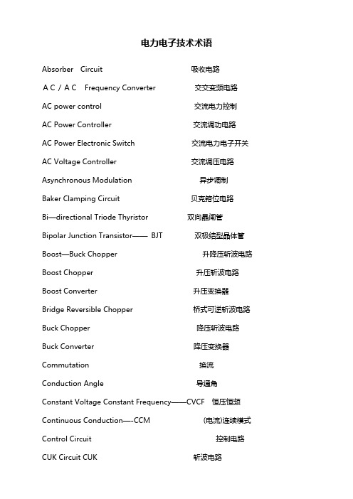
电力电子技术术语Absorber Circuit 吸收电路AC/ACFrequency Converter 交交变频电路AC power control 交流电力控制AC Power Controller 交流调功电路AC Power Electronic Switch 交流电力电子开关AC Voltage Controller 交流调压电路Asynchronous Modulation 异步调制Baker Clamping Circuit 贝克箝位电路Bi—directional Triode Thyristor 双向晶闸管Bipolar Junction Transistor——BJT 双极结型晶体管Boost—Buck Chopper 升降压斩波电路Boost Chopper 升压斩波电路Boost Converter 升压变换器Bridge Reversible Chopper 桥式可逆斩波电路Buck Chopper 降压斩波电路Buck Converter 降压变换器Commutation 换流Conduction Angle 导通角Constant Voltage Constant Frequency——CVCF恒压恒频Continuous Conduction—-CCM (电流)连续模式Control Circuit控制电路CUK Circuit CUK 斩波电路Current Reversible Chopper 电流可逆斩波电路Current Source Type Inverter——CSTI 电流(源)型逆变电路Cycloconvertor 周波变流器DC—AC—DC Converter 直交直电路DC Chopping 直流斩波DC Chopping Circuit直流斩波电路DC—DC Converter 直流-直流变换器Device Commutation 器件换流Direct Current Control 直接电流控制Discontinuous Conduction mode (电流)断续模式Displacement Factor 位移因数Distortion Power 畸变功率Double End Converter 双端电路Driving Circuit 驱动电路Electrical Isolation 电气隔离Fast Acting Fuse 快速熔断器Fast Recovery Diode 快恢复二极管Fast Recovery Epitaxial Diodes 快恢复外延二极管Fast Switching Thyristor 快速晶闸管Field Controlled Thyristor 场控晶闸管Flyback Converter 反激电流Forced Commutation 强迫换流Forward Converter 正激电路Frequency Converter 变频器Full Bridge Converter 全桥电路Full Bridge Rectifier 全桥整流电路Full Wave Rectifier 全波整流电路Fundamental Factor 基波因数Gate Turn-Off Thyristor--GTO可关断晶闸管General Purpose Diode 普通二极管Giant Transistor-—GTR 电力晶体管Half Bridge Converter 半桥电路Hard Switching 硬开关High Voltage IC 高压集成电路Hysteresis Comparison 带环比较方式Indirect Current Control 间接电流控制Indirect DC—DC Converter 直接电流变换电路Insulated-Gate Bipolar Transistor——IGBT 绝缘栅双极晶体管Intelligent Power Module—-IPM 智能功率模块Integrated Gate—Commutated Thyristor—-IGCT集成门极换流晶闸管Inversion 逆变Latching Effect 擎住效应Leakage Inductance 漏感Light Triggered Thyristo---LTT 光控晶闸管Line Commutation 电网换流Load Commutation 负载换流Loop Current 环流元件设备三绕组变压器:three—column transformer ThrClnTrans 双绕组变压器:double-column transformer DblClmnTrans 电容器:Capacitor并联电容器:shunt capacitor电抗器:Reactor母线:Busbar输电线:TransmissionLine发电厂:power plant断路器:Breaker刀闸(隔离开关):Isolator分接头:tap电动机:motor状态参数有功:active power无功:reactive power电流:current容量:capacity电压:voltage档位:tap position有功损耗:reactive loss无功损耗:active loss功率因数:power—factor功率:power功角:power—angle电压等级:voltage grade空载损耗:no—load loss铁损:iron loss铜损:copper loss空载电流:no—load current阻抗:impedance正序阻抗:positive sequence impedance负序阻抗:negative sequence impedance 零序阻抗:zero sequence impedance电阻:resistor电抗:reactance电导:conductance电纳:susceptance无功负载:reactive load 或者QLoad有功负载: active load PLoad遥测:YC(telemetering)遥信:YX励磁电流(转子电流):magnetizing current 定子:stator功角:power—angle上限:upper limit下限:lower limit并列的:apposable高压:high voltage低压:low voltage中压:middle voltage电力系统power system发电机generator励磁excitation励磁器excitor电压voltage电流current母线bus变压器transformer升压变压器step—up transformer高压侧high side输电系统power transmission system输电线transmission line固定串联电容补偿fixed series capacitor compensation 稳定stability电压稳定voltage stability功角稳定angle stability暂态稳定transient stability电厂power plant能量输送power transfer交流AC装机容量installed capacity电网power system落点drop point开关站switch station双回同杆并架double—circuit lines on the same tower 变电站transformer substation补偿度degree of compensation高抗high voltage shunt reactor无功补偿reactive power compensation故障fault调节regulation裕度magin三相故障three phase fault故障切除时间fault clearing time极限切除时间critical clearing time切机generator triping高顶值high limited value强行励磁reinforced excitation线路补偿器LDC(line drop compensation)机端generator terminal静态static (state)动态dynamic (state)单机无穷大系统one machine - infinity bus system 机端电压控制AVR电抗reactance电阻resistance功角power angle有功(功率)active power无功(功率) reactive power功率因数power factor无功电流reactive current下降特性droop characteristics斜率slope额定rating变比ratio参考值reference value电压互感器PT分接头tap下降率droop rate仿真分析simulation analysis传递函数transfer function框图block diagram受端receive—side裕度margin同步synchronization失去同步loss of synchronization 阻尼damping摇摆swing保护断路器circuit breaker电阻:resistance电抗:reactance阻抗:impedance电导:conductance电纳:susceptance导纳:admittance电感:inductance电容:capacitance一般术语电力电子变流器的型式(表1-2)电力电子开关和交流电力电子控制器电力电子设备的基本元件电力电子设备的电路和电路单元电力电子设备的运行电力电子设备的性能电力电子变流器的特性曲线稳定电源。
Utilities Policy7(1998)87–94Voltage control in a changing US electricity industryBrendan Kirby*,Eric HirstEnergy Division,Oak Ridge National Laboratory,Oak Ridge,TN37831-6206,USAAbstractAs the US electricity industry is restructured,the generation,transmission,and system-control equipment and functions that maintain voltages within the appropriate ranges are being deintegrated.These changes in industry structure require new institutional rules and markets to plan for additional voltage-support capacity,to reserve capacity for future use,and to deploy capacity in real time to meet current and contingency conditions.These services can be obtained through engineering mandates or through markets. Whether the location-specific nature of voltage control will permit the creation of competitive markets is not yet known. Voltage control is accomplished by managing reactive power on an alternating-current power system.Reactive power can be produced and absorbed by both generation and transmission equipment.Reactive-power devices differ substantially in the magnitude and speed of response and in their capital costs.System operators,transmission owners,generators,customers,power marketers, and government regulators need to pay close attention to voltage control as they restructure the US electricity industry.When generators are required to supply excessive amounts of reactive power,their real-power production must be curtailed. These opportunity costs are not currently compensated for in most regions.Current tariffs are based on embedded costs.These embedded-cost tariffs average about$0.51/MWh,equivalent to$1.5billion annually for the United States as a whole.Although this cost is low when compared with the cost of energy,it still aggregates to a significant amount of money.This paper explains why power systems require reactive power.It then examines the various types of generation and transmission resources used to supply reactive power and to control voltage.Finally it discusses how these resources are deployed and paid for in several reliability regions around the country.©1998Elsevier Science Ltd.All rights reserved.Keywords:Voltage control;Ancillary services;Reactive power;Restructuring;Deregulation1.BackgroundVoltage control and reactive-power management are two aspects of a single activity that both supports reliability and facilitates commercial transactions across transmission networks.The Federal Energy Regulatory Commission(FERC,1996,1997a)recognized the importance of voltage control by including it as an ancil-lary service in Order888,Reactive Supply and Voltage Control from Generation Sources.FERC differentiated generation-based activities from transmission-system-based activities,with the latter to be addressed under the basic transmission tariff.In this paper we examine both transmission and generator provision of the service to gain a fuller understanding of the overall situation. Generators and various types of transmission equip-ment are used to maintain voltages throughout the trans-mission system.Injecting reactive power into the system *Corresponding author.0957-1787/98/$19.00©1998Elsevier Science Ltd.All rights reserved. PII:S0957-1787(98)00006-X raises voltages,and absorbing reactive power lowers voltages.Voltage-support requirements are a function of the location and magnitudes of generator outputs and customer loads.These requirements can differ substan-tially from location to location and can change rapidly as the locations and magnitudes of generation and load change or if the transmission-system configuration changes.At very low levels of system load,transmission lines act as capacitors and increase voltages.At high loads,however,transmission lines absorb reactive power and lower voltages.Most transmission-system equip-ment(e.g.,capacitors,inductors,and tap-changing transformers)can respond to changes in voltage require-ments only slowly and in discrete steps.Some trans-mission-system equipment[e.g.,static VAR compen-sators(SVCs)]and generators can respond within cycles to changing reactive-power requirements.Voltages must be controlled for three reasons.First, both customer and power-system equipment is designed to operate within a range of voltages,usually within±5%of the nominal voltage.At low voltages,many types88 B.Kirby,E.Hirst/Utilities Policy7(1998)87–94of equipment perform poorly;light bulbs provide less illumination,induction motors can overheat and be dam-aged,and some electronic equipment will not operate at all.High voltages can damage equipment and shorten their lifetimes.Second,reactive power consumes transmission and generation capacity.To maximize the amount of real power that can be transferred across a congested trans-mission interface,reactive-powerflows must be minim-ized.Similarly,reactive-power production can limit a generator’s real-power capability.Third,moving reactive power on the transmission sys-tem incurs real-power losses.Both capacity and energy must be supplied to replace these losses.Voltage control is complicated by two additional fac-tors.First,the transmission system itself is a nonlinear consumer of reactive power,depending on system load-ing.System reactive requirements vary in time as load levels and load and generation patterns change. Second,the bulk-power system is composed of many pieces of equipment,any one of which can fail at any time.Therefore,the system is designed to withstand the loss of any single piece of equipment and to continue operating without impacting any customers.These two factors result in a dynamic reactive-power requirement.The loss of a generator or a major trans-mission line can have the compounding effect of reduc-ing the reactive supply and,at the same time,reconfig-uringflows such that the system is consuming additional reactive power.At least a portion of the reactive supply must be capable of responding quickly to changing reactive-power demands and to maintain acceptable volt-ages throughout the system.Thus,just as an electrical system requires real-power reserves to respond to contin-gencies,so too it must maintain reactive-power reserves. Loads can also be both real and reactive.Reactive loads incur more voltage drop and reactive losses in the transmission system than do similar size(MVA)real loads.Vertically integrated utilities often included charges for provision of reactive power to loads in their rates.With restructuring,the trend is to restrict loads to operation at near zero reactive-power demand(i.e.,a power factor1of1).The California ISO limits loads to power factors between0.97lagging(absorbing reactive power)and0.99leading(generating reactive power) (Pacific Gas and Electric et al.,1997).The significant differences between the real and reactive ancillary services are:Real power can be delivered over much greater dis-tances so the supplying resources are not as location 1The power factor(PF)is the ratio of real power(in MW)to appar-ent power(MVA).Apparent power is related to real and reactive power(MVAR)according to MVA=√[(MW)2+(MVAR)2].constrained,whereas reactive resources must be dis-tributed throughout the power system.Generation of real power requires the conversion from an energy resource,such as chemical or nuclear fuel,sunlight,or a mechanical resource like wind or waterflow,whereas reactive power requires almost no“fuel”to produce.Much of the complication associated with voltage control comes from combining these various aspects into a single service.Rather than splitting this service along functional lines,FERC and the industry elected to split the service based on commercial ownership of the resources that supply the service.The requirements and compensation for generation-based resources fall under FERC’s voltage-control service.Transmission-based resources are addressed under the general transmission tariff.The range of physical requirements(speed of response,need for contingency reserve,etc.)still exist, but they are not addressed in the basic definitions as they are for real-power services.As with most ancillary services,the need for voltage control stems from an overall system requirement, requires resources capable of supplying that need,and must have a central-control function directing those resources to meet the requirement in real time.Suppliers of the resources are not able to independently determine the system’s voltage-control needs.Only the system operator has sufficient information to know the system requirements,both current and contingency,and to deploy those resources effectively.Similarly,while ser-vice requirements result from customer choices in terms of load patterns and generation choices,the customers do not have sufficient information about the configur-ation of the transmission system or the actions of other customers to know what reactive-power requirements will result ahead of time from their choices.Again,the system operator is needed to deploy resources to meet requirements and to transmit appropriate price signals to customers.2.Transmission-system voltage controlIn moving power from generators to loads,the trans-mission network introduces both real and reactive losses. Real-power losses arise because aluminum and copper (the materials most often used for transmission lines)are not perfect conductors;they have resistance.The reactive nature of transmission lines is associated with the geometry of the conductors themselves(primarily the radius of the conductor)and the conductor configuration (the distances between each conductor and ground and the distances among conductors).The reactive-power behavior of transmission lines is89B.Kirby,E.Hirst /Utilities Policy 7(1998)87–94Fig.1.Transmission lines supply reactive power to the system when lightly loaded but absorb reactive power when heavily loaded.These results are for a 100-mile line with voltages supported at both ends.complicated by their inductive and capacitive character-istics.As shown in Fig.1,at low line loadings,the capacitive effect dominates,and generators and trans-mission-related reactive equipment must absorb reactive power to maintain line voltages within their appropriate limits.On the other hand,at high line loadings,the inductive effect dominates,and generators,capacitors,and other reactive devices must produce reactive power.The balance point at which the inductive and capacitive effects cancel each other (what is called surge-imped-ance loading)is typically about 40%of the line’s ther-mal capacity.Fig.1also shows that at both low and high line load-ings (but not around the surge-impedance loading),reactive losses are greater than real losses.At full line loading,reactive losses are five times greater than real losses for a 230kV line and nine times higher for a 345kV line.(At 50%of line loading,the factors are two and four for the 230and 345kV lines,respectively.)If uncompensated,these line losses reduce the amount of real power that can be transmitted from generators to loads.Fig.2shows how transmission-linecapacityFig.2.Absent reactive compensation to maintain voltages,trans-mission-line capacity is limited to shorter lengths.decreases as the line length increases if there is no volt-age support on the line.At short distances,the line’s capacity is limited by thermal considerations;at inter-mediate distances the limits are related to voltage drop;and beyond roughly 300–350miles,stability limits dominate.An East Central Area Reliability Coordination Agreement (1997)study showed that the addition of ser-ies capacitors to boost voltages would increase the capacity of a particular transmission line by about 60%.3.Voltage-control equipmentPower-system designers and operators can use various devices to control voltages by injecting,absorbing,or forcing the flow of reactive power.These devices differ in several important characteristics:response speed,con-tinuity of control,response to system voltage changes,and capital and operating costs (Table 1).Kirby and Hirst (1997)provide details on these alternatives.For brevity,we discuss only generation here,because FERC separated generator provision of voltage control from transmission provision.3.1.GenerationA generator’s primary function is to convert fuel (or some other energy resource)into electric power.Almost all synchronous generators also have considerable con-trol over their terminal voltage and reactive-power out-put.The ability of a generator to provide reactive support depends on its real-power production.Fig.3shows the combined limits on real and reactive production for a typical generator.The generator prime mover (e.g.,the steam turbine)is usually designed with less capacity than the electric generator,resulting in the prime-mover limit in Fig.3.The designers recognize that the generator will be producing reactive power most of the time.This gen-erator,at maximum real-power output,can produce 0.62MVAR for every megawatt of real-power output,based on the 0.85lagging power-factor limit.Or it can absorb 0.41MVAR for every megawatt of real-power output,based on the leading power-factor limit.To produce or absorb additional VARs beyond these limits would require a reduction in the real-power output of the unit.Historically,only the capital and operating costs that could be associated with the extra equipment (e.g.,parts of the stator,rotor,voltage regulator,and exciter plus the operating costs associated with field losses)required for voltage control were charged to the voltage-control function.In a restructured industry,the opportunity costs associated with reduced real-power sales when excessive reactive power is required will be a key part of the cost90 B.Kirby,E.Hirst /Utilities Policy 7(1998)87–94Table 1Characteristics of voltage-control equipment Equipment typeSpeed of responseAbility to supportCosts voltageCapital (per kVAR)Operating Opportunity GeneratorFast Excellent,additional Difficult to separate High Yes short-term capacity Synchronous condenser FastExcellent,additional $30–35High No short-term capacity Capacitor Slow,stepped Poor,drops with V 2$8–10None No SVC aFast Poor,drops with V 2$45–50Moderate No STATCOM aFast Fair,drops with V $50–55Moderate No Distributed generationFast Fair,drops with VDifficult to separateHighYesaSVC,static VAR compensator;STATCOM,static synchronouscompensator.Fig.3.Reactive-power capability depends on real-power production for a synchronous generator.of providing voltage control from generation.2Generator reactive-power capability is determined during the design of the machine.Because capital costs are involved in providing this capability,builders of new generating units will likely not include voltage-support capability unless (1)the market or a regulated tariff com-pensates the generators or (2)voltage-support capability is a requirement of connecting to the grid.3.2.Differences among equipment typesGenerators,synchronous condensers,SVCs,and STATCOMs all provide fast,continuously controllable voltage control.Load-tap changer transformers provide2The costs and prices for voltage support will likely be highly non-linear with system load (Hirst and Kirby,1997).At very high loads,the opportunity cost of voltage support will far exceed the embedded cost because of the required cut in real-power output and the likely high energy price during such peak-demand periods.nearly continuous voltage control but they are slow.Because the transformer moves reactive power from one bus to another,the control gained at one bus is at the expense of the other.Capacitors and inductors are not variable and offer control only in large steps.An unfortunate characteristic of capacitors and capaci-tor-based SVCs is that output drops dramatically when voltage is low and support is needed most.STATCOMs provide more support under low-voltage conditions than do capacitors or SVCs because their capability drops lin-early with voltage.The output of rotating machinery (i.e.,generators and synchronous condensers)generally rises with dropping voltage.Generators and synchronous condensers generally have additional emergency capacity that can be used for a limited time.Voltage-control characteristics favor the use of gener-ators and synchronous condensers.Costs,on the other hand,favor capacitors.Generators have extremely high capital costs because they are designed to produce real power,not reactive power.Even the incremental cost of reactive support from generators is high,although it is difficult to unambiguously separate reactive-from real-power costs.Operating costs for generators are high as well because they can involve real-power losses.Finally,because generators have other uses,they experience opportunity costs when called on simultaneously to pro-vide high levels of reactive and real power.Synchronous condensers have the same characteristics as generators;but,because they are built solely to provide reactive sup-port,their capital costs are not as high and they incur no opportunity costs.SVCs and STATCOMs are high-cost devices as well,although their operating costs are lower than those for synchronous condensers and gener-ators.4.Emerging issues on voltage controlSystem operation has three objectives when managing reactive power and voltages.First,it must maintain91 B.Kirby,E.Hirst/Utilities Policy7(1998)87–94adequate voltages throughout the transmission system for both current and contingency conditions.Second,it seeks to minimize congestion of real-powerflows.Third, it seeks to minimize real-power losses.These were the system-control objectives before restructuring,and they will continue to be the objectives after restructuring of the US electricity industry.Restructuring will almost surely change the mech-anisms that system operators use to acquire and deploy reactive-power resources.Historically,the system oper-ator,generators,transmission devices,and transmission system were all owned and operated by the same entity. In the future,the entities that own and operate generation may differ from those that own transmission,and both may differ from the system operator(which likely will control the transmission system).These changes will require the creation of market structures plus require-ments for connection to the transmission system and the operation of certain equipment.Absent new coordinating functions,voltage-control investments will no longer be optimized across generation and transmission alterna-tives.The system operator must have the authority to deploy resources to meet the system’s voltage-control objectives;this authority is required for operational plan-ning(up to a day ahead)and real-time operation.Not surprisingly,more progress has been made in addressing the technical objectives of managing voltages than in developing market structures to perform this function in a restructured industry.The North American Electric Reliability Council(1996)guidance focuses on the concept of control-area responsibility for controlling voltage and reactive resources,allowing control areas to develop appropriate rules.Control areas are to maintain sufficient reactive resources to support voltages under first-contingency conditions.Each control area should take care of its own needs and avoid placing a burden on other control areas.The North American Electric Reliability Council policies offer little guidance on what resources should be available or how the system operator should acquire and deploy them,leaving these decisions to the regional reliability councils and the individual control areas.4.1.Technical guidance and compensation rules Regional councils differ in the level of detailed guid-ance they offer their members.The Southwest Power Pool,the Southeastern Electric Reliability Council,and the Florida Reliability Coordinating Council provide only general guidance to their members on maintaining adequate voltage support during normal and contingency conditions.Individual control-area operators use the authority of these directives to order specific actions directed at voltage support.The Electric Reliability Council of Texas(1997)provides additional direction on required generator capability and authorizes control-area operators to use each generator’s full reactive capability to maintain system voltages.Regions containing tight power pools,such as the Mid-Atlantic Area Council and the Northeast Power Coordinating Council along with their member pools, have more detailed rules concerning both generator-capability requirements and system operations to main-tain voltages.These rules govern which conditions to study when determining voltage-support requirements and generator-reactive-capability requirements as well as their use.Rules governing voltage-control actions to be taken by system operators generally use the lowest-cost resourcesfirst and delay expensive actions,such as redispatching generator real-power output.When the problem is addressed at all,generators are typically com-pensated at cost if they are required to adjust their real-power output to support voltages.The Northeast Power Coordinating Council(1992)operating guide provides a typical example of the order of control actions: Low-cost transmission-system and generation-con-trol actionsadjust transformer tapsswitch capacitors and reactorsadjust SVCsuse full reactive capability of online generatorsHigher-cost adjustments to economical energy pro-ductionstart additional generationmodify economy transactions with other areas and/ordeviate from economic dispatchoperate hydro units as synchronous condensers,where possiblereschedule pumped-hydro units to generate or pumppurchase energyAdjustments to the transmission-system configur-ationswitch out transmission lines if security limits willnot be violatedNone of the previously mentioned organizations has fully addressed voltage control in a restructured,com-petitive generation market.California’s efforts at restruc-turing have extended,or at least made more explicit,the relationships among the various parties when providing reactive power(Pacific Gas and Electric et al.,1997). California’s ISO is charged with the planning and operating responsibilities associated with maintaining reliability and facilitating markets.One of these responsibilities involves assuring the adequacy and reliability of voltage support.But the California ISO has no generation resources of its own.The ISO obtains reactive-power-generation resources by making them a condition of connection to the grid.All generators are required to have a continuous operating range from0.9092 B.Kirby,E.Hirst/Utilities Policy7(1998)87–94power factor lag to0.95power factor lead.The ISO has the right to direct generators—without compensation—to operate anywhere within this range.Only if the ISO requires a generator to operate outside this range will the ISO compensate the generator.4.2.Requirements in a restructured industryISO management of reactive resources involves equipment capability and actual delivery.That is,the ISO must acquire(either by mandate or purchase)the right to specified amounts of reactive-power capability. That power must then be delivered(or absorbed)in response to the time-varying and location-specific requirements of the system.The system operator uses computer models to help determine what voltage-control resources are needed and,to a lesser extent,how to deploy those resources most efficiently.A constrained optimal-power-flow analysis can determine the reactive-power dispatch that minimizes real-power losses or can calculate location-specific reactive-power prices(El-Keib and Ma,1997). Including physical limits,bus voltage requirements,and contingencies as constraining conditions assures that the calculated solutions meet the physical requirements.If all costs are presented to the system operator,the optimal powerflow can be used tofind a least-cost solution. Unfortunately,the computed marginal prices for reactive power are very sensitive to the particular configuration of the electrical grid,which can change quite rapidly(Li and David,1994).Application of alternative objective functions can lead to very different uses of reactive-power devices.Accord-ing to one analysis,traditional VAR dispatch seeks to minimize control actions(Dandachi et al.,1996).Mini-mizing the cost of voltage control could lower voltage-support costs by about one fourth.The resulting solution, however,leads to an entirely different voltage profile that requires many more control actions,such as adjust-ments of transformer taps.In a competitive environment,determination of who has provided what service will be more e of claimed capability may not be adequate.The actual VAR output from a generator may not match the manu-facturer’s capability specifications.Public Service Com-pany of Colorado found that operating limits often pre-vent generators from providing full rated VAR output. Adjustment of tap settings on the step-up(and other) transformers,adjustment of station service voltage lev-els,and recalibrating and setting alarms and meters are often needed to increase the actual VAR output.Better training of operators on the use of voltage-control equip-ment is also important.This utility achieved a500-MVAR increase in actual capability at13generating units,a50%increase in output(Panvini and Yohn, 1995).Because actual and predicted performance might not match well,the East Central Area Reliability Coordi-nation Agreement(1996)developed methods for rating the real-and reactive-power performance of generating units under normal operating conditions.The reactive-power tests must be conducted at least once every two years and require maintenance of scheduled voltages for at least two hours.ISOs will likely develop and implement similar methods to be sure that the reactive supplies contracted to the ISO can and do perform as specified.A corresponding set of penalties must also be developed to deter persistent noncompliance.ISOs can acquire reactive resources either through mandates or purchases.The California ISO(as noted above)chose the mandatory approach.To the extent that reactive supplies are not geographically restricted,it might be possible to create competitive markets for the acquisition of such resources.Many believe that the location limitations on reactive resources are sufficiently great that competitive markets cannot develop for this service.Other ISOs plan to pay generators their embedded costs for reactive resources.Unfortunately,determining the embedded cost of generator-provided reactive power is ambiguous at best.This ambiguity occurs because the same equipment is used to provide both real and reactive power.What percentages,for example,of the exciter, generator stator,generator rotor,turbine assembly,and step-up transformer should be assigned to each function?A generation-owning utility has a strong incentive to shift as much of these joint costs to the regulated func-tion(voltage control in this case)and away from the competitive function(energy).This cost shifting,if suc-cessful,would increase the regulated return on voltage control and improve the generators’competitive position by reducing thefixed costs it has to recover in competi-tive energy markets.A Southern Company proceeding before FERC illus-trates well these complexities.(We have no opinion on the reasonableness of either Southern’s request or FERC’s decision.)Southern proposed to assign some of the cost of the turbines and100%of the costs of the exciter and its cooling system to reactive power.FERC (1997b)disagreed and assigned100%of the turbine cost to real-power production.Southern computed its reactive-power charges on the basis of a pair of load-flow studies,a base case and a transaction case.Southern used the difference in reactive-power requirements between the two cases as the basis for its proposed charges.FERC rejected the use of incremental pricing for generator reactive power because Southern was using embedded-cost pricing for transmission-supplied reactive power.Finally,the ISOs and the other participants in bulk-power markets will need to decide which entity has the responsibility and authority to plan for and determine the。
第45卷第1期Vol.45 N o.1计算机工程Computer Engineering2019年1月January2019•体系结构与软件技术• 文章编号:1000-3428(2019)01-0023-06 文献标志码:A 中图分类号:TP399混合关键性系统寿命优化的任务调度算法鞠芊蕾,曹坤,梁文彬,魏同权(华东师范大学计算机科学技术系,上海2000(2)摘要:为延长混合关键性系统的设备寿命,考虑瞬时性、永久性2种故障并采取容错方案满足安全需求,提出一种两阶段解决方案。
利用动态电压频率调整技术为每个任务确定运行频率,确保热循环对设备寿命的损害最小。
使用重执行技术,在可靠性约束和可调度性约束下对设备寿命进行分析,构建一个多目标非线性规划问题,从而得到最优解。
仿真结果表明,与R A N D、M F P R、M R P F、D P A S4种算法相比,该算法在保证系统可调度与可靠性的前提下,可使系统寿命最多延长47%。
关键词:混合关键性系统;寿命感知;可调度性;动态电压频率调整;调度机制中文引用格式:鞠芊蕾,曹坤,梁文彬,等.混合关键性系统寿命优化的任务调度算法[J].计算机工程,2019,45(1):23-28 .英文引用格式:JU Qianlei,C A O K u n,L I A N G Wenbin,et al.Task scheduling algorithm for lifetimeoptimization ofmixed-critical systems'J].Computer Engineering,2019,45 (1) :23-28.Task Scheduling Algorithm for Lifetime Optimization of Mixed-critical SystemsJ U Qianlei,C A O K u n,L I A N G W e n b i n,W E I Tongquan(D epartm ent of Com puter Science and Techno l o g y,East China N orm a l Universit;^,Shanghai 2000(2,C hina)[Abstract]In order to extend the l i f e of equipment for mixed-critical systems,consideringerors and taking f ault-tolerant solutions to meet safety requirements,a two-stage solution i s proposed.The DynamicVoltage Frequency Scaling(D V F S)t echnique i s used to determine the operating frequency for each task,ensuring thatthermal cycling minimizes damage to equipment li f e.By using the re-execution technolog under the constraint o f re l i a b i l i t y constraint and schedulability,and a multi-objective nonlinear programming problem i sconstructed to obtain the optimal solution.Simulation results show that compared with the four a R A N D、M F P R、M R P F a n d D P A S,t h is algorithm can extend the l i f e of the system by up to47% under the premise ofensu,ing system scheduling and,eliability.[Keywords]mixed-critical systems&lifetime-aware&schedulability&Dynamic VoltageFrequency Scaling(D V F S) &scheduling mechanismDOI:10.19678/j.issn.1000-3428.00493620概述关键性系统是指系统必须高度可靠,即随着系 统扩展仍然可以维持可靠性,而不会产生高昂的成 本[1]。
第22卷第2期2002年2月 中 国 电 机 工 程 学 报Proceedings of the CSEEV ol.22N o.F eb.20022002Chin.Soc.for Elec.Eng.文章编号:0258 8013(2002)02 0099 04电压源型逆变器三角载波电流控制新方法戴朝波,林海雪(中国电力科学研究院,北京100085)A NOVEL TRIANGULAR CARRIER CURRENT C ONTROLFOR VOLTAGE SOURCE INVERTERSDAI Chao bo LIN H ai xue(China Electric Power Research Institute,Beijing100085,China)ABSTRAC T:T his paper analyzes the frequency character istics of the conventional triangular carr ier current control for voltage source inver ters and the frequency character i stics are influenced by the integral coefficient of t he PI r eg ulator.It is a v ery roug h approx imation that the current contro l s behavior of the voltage source inverter i s r epresented by the first order time delay trans fer function.T herefo re,the analysis based on this approximation may be inappropr iate or inaccurate in some situations.Based on t he g iven inter ference pre compensation,a novel tr iangular carri er curr ent control is put forward through the addition of the two g iven distur bance signals pre compensation to a closed loop feed back control system.T he no vel control takes full advantag e of merits both of the forward system and of the feedback system.It is undeniable that the novel control carr ies more w eight than the conventional control as far as the tracking performance is con cer ned.T he analysis in t he frequency domain and the results of applications in two examples,i.e.trapezoidal current w aveform and activ e power filters,confir m the conclusion.M orever,the cost of the nov el control is manifested in the incr eased number of basic blocks such as gain,der ivative and addition,however t hey are easy to implement and economical.KEY WORDS:modulation technique;voltage sour ce inver ter; t riangular carrier control摘要:该文分析了三角载波电流控制传统方法的频率特性和PI调节器中的积分系数取值对该频率特性的影响,如果用一阶惯性环节去近似地模拟逆变器的频率特性,则会有一定的误差。

DFIG在微电网中的电压频率协调控制策略赵晶晶,徐成斯,洪婉莎,徐传琳(上海电力学院电气工程学院,上海 200090)摘要:为了抑制双馈感应风电机组(Doubly-fed Induction Generator,DFIG)因自身有功输出波动导致的微电网电压频率波动,提高其对微电网孤岛运行下的电压频率支撑能力,研究分析了DFIG有功虚拟惯量控制以及定子侧无功功率极限,提出了一种基于f-P和V-Q下垂控制的DFIG电压频率协调控制策略。
在DFIG V-Q下垂控制中引入逻辑积分环节,在不额外使用补偿装置下有效抑制电压频率的持续波动,并且在微电网电压频率跌落时,能够与其他采用下垂控制的分布式电源(Distributed Generator,DG)构成对等控制策略,共同为微电网提供电压频率支撑。
最后在DIgSILENT仿真软件中搭建了微电网模型,仿真结果验证了控制策略的有效性。
关键词:微电网;双馈感应风力发电机;对等控制;频率控制;电压控制;下垂控制中图分类号:文献标志码:A 文章编号:Voltage and Frequency Coordination Control Strategy ofDFIG in Micro-gridZHAO Jingjing,XU Chengsi,HONG Wansha,XU Chuanlin (School of Electrical Engineering,Shanghai University of Electric Power,Shanghai 200090,China)Abstract:In order to suppress the micro-grid voltage and frequency fluctuation caused by the active power output fluctuation of the doubly fed wind turbine, improve its voltage and frequency support ability, the DFIG active virtual inertia control and stator reactive power limit are analyzed. Based on f-P, V-Q droop control,the voltage and frequency coordination control strategy of DFIG with a logic integration added in V-Q droop control is presented. This control strategy allows DFIG to suppress the continuous voltage fluctuation itself without additional compensation device.When there is voltage-frequency drop, it allows DFIG to constitute a peer-to-peer control strategy with other distributed generator to provide support for the voltage and frequency of micro grid. Finally, the DIgSILENT simulation software is built to simulate the micro grid model. The simulation results verify the effectiveness of the proposed control strategy.Key words:micro-grid; doubly-fed induction generator; peer to peer control strategy; frequency control; voltage control; droop control微电网并网运行时,微电网电压频率可由外部大电网提供支撑;微电网孤岛运行时,微电网电压频率稳定由其内部分布式电源(Distributed Generator,DG)控制来实现。
常见电力电子专业英语词汇电压源voltage source 电流源current source理想电压源ideal voltage source理想电流源ideal current source伏安特性volt-ampere characteristic电动势electromotive force电压voltage 电流current 电位potential电位差potential difference 欧姆Ohm 伏特Volt安培Ampere 瓦特Watt 焦耳Joule 电路circuit电路元件circuit element 电阻resistance 电阻器resistor 电感inductance电感器inductor 电容capacitance电容器capacitor电路模型circuit model 参考方向reference direction参考电位reference potential 欧姆定律Ohm’s law基尔霍夫定律Kirchhoff’s law基尔霍夫电压定律Kirchhoff’s voltage law(KVL)基尔霍夫电流定律Kirchhoff’s current law(KCL)结点node 支路branch 回路loop 网孔mesh支路电流法branch current analysis 网孔电流法mesh current analysis结点电位法node voltage analysis 电源变换source transformations叠加原理superposition theorem 网络network无源二端网络passive two-terminal network有源二端网络active two-terminal network戴维宁定理Thevenin’s theorem诺顿定理Norton’s theorem开路(断路)open circuit 短路short circuit开路电压open-circuit voltage 短路电流short-circuit current直流电路direct current circuit (dc)交流电路alternating current circuit (ac)正弦交流电路sinusoidal a-c circuit 平均值average value有效值effective value均方根值root-mean-squire value (rms) 瞬时值instantaneous value电抗reactance 感抗inductive reactance 容抗capacitive reactance法拉Farad 亨利Henry 阻抗impedance 复数阻抗complex impedance相位phase 初相位initial phase 相位差phase difference相位领先phase lead 相位落后phase lag 倒相,反相phase inversion频率frequency 角频率angular frequency 赫兹Hertz相量phasor 相量图phasor diagram有功功率active power 无功功率reactive power视在功率apparent power 功率因数power factor功率因数补偿power-factor compensation串联谐振series resonance 并联谐振parallel resonance谐振频率resonance frequency 频率特性frequency characteristic幅频特性amplitude-frequency response characteristic相频特性phase-frequency response characteristic截止频率cutoff frequency 品质因数quality factor通频带pass-band 带宽bandwidth (BW) 滤波器filter一阶滤波器first-order filter 二阶滤波器second-order filter低通滤波器low-pass filter 高通滤波器high-pass filter带通滤波器band-pass filter 带阻滤波器band-stop filter转移函数transfer function 波特图Bode diagram 傅立叶级数Fourier series三相电路three-phase circuit 三相电源three-phase source对称三相电源symmetrical three-phase source对称三相负载symmetrical three-phase load相电压phase voltage 相电流phase current线电压line voltage 线电流line current三相三线制three-phase three-wire system三相四线制three-phase four-wire system三相功率three-phase power 星形连接star connection(Y-connection)三角形连接triangular connection(D- connection ,delta connection)中线neutral line 暂态transient state 稳态steady state暂态过程,暂态响应transient response换路定理low of switch 一阶电路first-order circuit三要素法three-factor method 时间常数time constant 积分电路integrating circuit 微分电路differentiating circuit磁路与变压器磁场magnetic field 磁通flux磁路magnetic circuit 磁感应强度flux density磁通势magnetomotive force 磁阻reluctance直流电动机dc motor 交流电动机ac motor异步电动机asynchronous motor 同步电动机synchronous motor三相异步电动机three-phase asynchronous motor单相异步电动机single-phase asynchronous motor旋转磁场rotating magnetic field 定子stator 转子rotor 转差率slip起动电流starting current 起动转矩starting torque额定电压rated voltage 额定电流rated current 额定功率rated power机械特性mechanical characteristic按钮button 熔断器fuse 开关switch 行程开关travel switch继电器relay 接触器contactor常开(动合)触点normally open contact常闭(动断)触点normally closed contact时间继电器time relay 热继电器thermal overload relay中间继电器intermediate relay可编程控制器programmable logic controller语句表statement list 梯形图ladder diagram本征半导体intrinsic semiconductor 掺杂半导体doped semiconductorP型半导体P-type semiconductorN型半导体N--type semiconductor自由电子free electron 空穴hole 载流子carriersPN结PN junction 扩散diffusion 漂移drift 二极管diode硅二极管silicon diode 锗二极管germanium diode 阳极anode 阴极cathode发光二极管light-emitting diode (LED) 光电二极管photodiode稳压二极管Zener diode 晶体管(三极管)transistorPNP型晶体管PNP transistor NPN型晶体管NPN transistor发射极emitter 集电极collector 基极base电流放大系数current amplification coefficient场效应管field-effect transistor (FET) P沟道p-channel N沟道n-channel结型场效应管junction FET(JFET)金属氧化物半导体metal-oxide semiconductor (MOS)耗尽型MOS场效应管depletion mode MOSFET(D-MOSFET)增强型MOS场效应管enhancement mode MOSFET(E-MOSFET)源极source 栅极grid 漏极drain跨导transconductance 夹断电压pinch-off voltage热敏电阻thermistor 开路open 短路shorted放大器amplifier 正向偏置forward bias 反向偏置backward bias静态工作点quiescent point (Q-point) 等效电路equivalent circuit电压放大倍数voltage gain 总的电压放大倍数overall voltage gain饱和saturation 截止cut-off放大区amplifier region 饱和区saturation region截止区cut-off region 失真distortion饱和失真saturation distortion 截止失真cut-off distortion零点漂移zero drift 正反馈positive feedback 负反馈negative feedback串联负反馈series negative feedback并联负反馈parallel negative feedback共射极放大器common-emitter amplifier 射极跟随器emitter-follower共源极放大器common-source amplifier 共漏极放大器common-drain amplifier多级放大器multistage amplifier阻容耦合放大器resistance-capacitance coupled amplifier直接耦合放大器direct- coupled amplifier输入电阻input resistance 输出电阻output resistance负载电阻load resistance 动态电阻dynamic resistance负载电流load current旁路电容bypass capacitor 耦合电容coupled capacitor直流通路direct current path 交流通路alternating current path直流分量direct current component 交流分量alternating current component变阻器(电位器)rheostat 电阻(器)resistor 电阻(值)resistance电容(器)capacitor 电容(量)capacitance 电感(器,线圈)inductor 电感(量),感应系数inductance 正弦电压sinusoidal voltage 差动放大器differential amplifier运算放大器operational amplifier(op-amp)失调电压offset voltage 失调电流offset current共模信号common-mode signal 差模信号different-mode signal共模抑制比common-mode rejection ratio (CMRR)积分电路integrator(circuit)微分电路differentiator(circuit)有源滤波器active filter 低通滤波器low-pass filter高通滤波器high-pass filter 带通滤波器band-pass filter带阻滤波器band-stop filter 波特沃斯滤波器Butterworth filter切比雪夫滤波器Chebyshev filter 贝塞尔滤波器Bessel filter截止频率cut-off frequency 上限截止频率upper cut-off frequency下限截止频率lower cut-off frequency 中心频率center frequency带宽Bandwidth 开环增益open-loop gain 闭环增益closed-loop gain 共模增益common-mode gain 输入阻抗input impedance电压跟随器voltage-follower 电压源voltage source 电流源current source单位增益带宽unity-gain bandwidth 频率响应frequency response频响特性(曲线)response characteristic 波特图the Bode plot稳定性stability 补偿compensation 比较器comparator迟滞比较器hysteresis comparator 阶跃输入电压step input voltage仪表放大器instrumentation amplifier 隔离放大器isolation amplifier 对数放大器log amplifier 反对数放大器antilog amplifier反馈通道feedback path 反向漏电流reverse leakage current相位phase 相移phase shift 锁相环phase-locked loop(PLL)锁相环相位监测器PLL phase detector 和频sum frequency差频difference frequency 振荡器oscillator RC振荡器RC oscillator LC振荡器LC oscillator正弦波振荡器sinusoidal oscillator三角波发生器triangular wave generator方波发生器square wave generator 幅度magnitude 电平level饱和输出电平(电压)saturated output level功率放大器power amplifier交越失真cross-over distortion甲类功率放大器class A power amplifier乙类推挽功率放大器class B push-pull power amplifier OTL功率放大器output transformerless power amplifier OCL功率放大器output capacitorless power amplifier半波整流full-wave rectifier 全波整流half-wave rectifier电感滤波器inductor filter 电容滤波器capacitor filter串联型稳压电源series (voltage) regulator开关型稳压电源switching (voltage) regulator集成稳压器IC (voltage) regulator晶闸管及可控整流电路晶闸管thyristor单结晶体管unijunction transistor(UJT)可控整流controlled rectifier可控硅silicon-controlled rectifier峰点peak point 谷点valley point控制角controlling angle 导通角turn-on angle 二进制binary二进制数binary number 十进制decimal 十六进制hexadecimal二-十进制binary coded decimal (BCD)门电路gate三态门tri-state gate 与门AND gate 或门OR gate 非门NOT gate 与非门NAND gate 或非门NOR gate异或门exclusive-OR gate 反相器inverter布尔代数Boolean algebra 真值表truth table 卡诺图the Karnaugh map逻辑函数logic function 逻辑表达式logic expression组合逻辑电路combination logic circuit 译码器decoder 编码器coder 比较器comparator 半加器half-adder 全加器full-adder七段显示器seven-segment display时序逻辑电路sequential logic circuit R-S触发器R-S flip-flop D触发器 D flip-flop J-K触发器J-K flip-flop主从型触发器master-slave flip-flop 置位set 复位reset直接置位端direct-set terminal 直接复位端direct-reset terminal 寄存器register异或门exclusive-OR gate 反相器inverter布尔代数Boolean algebra 真值表truth table 卡诺图the Karnaugh map逻辑函数logic function 逻辑表达式logic expression组合逻辑电路combination logic circuit 译码器decoder 编码器coder 比较器comparator 半加器half-adder 全加器full-adder七段显示器seven-segment display时序逻辑电路sequential logic circuit R-S触发器R-S flip-flop D触发器 D flip-flop J-K触发器J-K flip-flop主从型触发器master-slave flip-flop 置位set 复位reset直接置位端direct-set terminal 直接复位端direct-reset terminal寄存器register 移位寄存器shift register双向移位寄存器bidirectional shift register 计数器counter同步计数器synchronous counter 异步计数器asynchronous counter加法计数器adding counter 减法计数器subtracting counter 定时器timer清除(清0)clear 载入load时钟脉冲clock pulse 触发脉冲trigger pulse 上升沿positive edge下降沿negative edge 时序图timing diagram 波形图waveform单稳态触发器monostable flip-flop 双稳态触发器bistable flip-flop无稳态振荡器astable oscillator 晶体crystal555定时器555 timer 模拟信号analog signal 数字信号digital signalAD转换器analog -digital converter (ADC)DA转换器digital-analog converter (DAC)半导体存储器只读存储器read-only memory(ROM)随机存取存储器random-access memory(RAM)可编程ROM programmable ROM(PROM)发电机generator 励磁excitation 励磁器excitor 电压voltage电流current 升压变压器step-up transformer 母线bus变压器transformer 空载损耗:no-load loss铁损:iron loss 铜损:copper loss空载电流:no-load current 有功损耗:reactive loss 无功损耗:active loss输电系统power transmission system 高压侧high side输电线transmission line 高压: high voltage 低压:low voltage 中压:middle voltage 功角稳定angle stability 稳定stability电压稳定voltage stability 暂态稳定transient stability电厂power plant 能量输送power transfer 交流AC 直流DC电网power system 落点drop point开关站switch station 调节regulation高抗high voltage shunt reactor 并列的:apposable 裕度margin故障fault 三相故障three phase fault分接头:tap 切机generator triping 高顶值high limited value 静态static (state)动态dynamic (state) 机端电压控制AVR电抗reactance 电阻resistance功角power angle 有功(功率)active power 电容器:Capacitor电抗器:Reactor 断路器:Breaker 电动机:motor功率因数:power-factor 定子:stator 阻抗:impedance 功角:power-angle电压等级:voltage grade 有功负载: active load PLoad无功负载:reactive load 档位:tap position 电阻:resistor电抗:reactance 电导:conductance电纳:susceptance 上限:upper limit 下限:lower limit正序阻抗:positive sequence impedance负序阻抗:negative sequence impedance零序阻抗:zero sequence impedance 无功(功率)reactive power功率因数power factor 无功电流reactive current 斜率slope额定rating 变比ratio 参考值reference value电压互感器PT 分接头tap 仿真分析simulation analysis下降率droop rate 传递函数transfer function 框图block diagram受端receive-side功率因数:power-factor 定子:stator阻抗:impedance 功角:power-angle 电压等级:voltage grade有功负载: active load PLoad 无功负载:reactive load档位:tap position 电阻:resistor 电抗:reactance 电导:conductance电纳:susceptance 上限:upper limit 下限:lower limit正序阻抗:positive sequence impedance负序阻抗:negative sequence impedance零序阻抗:zero sequence impedance 无功(功率)reactive power功率因数power factor 无功电流reactive current 斜率slope额定rating 变比ratio 参考值reference value 电压互感器PT分接头tap 仿真分析simulation analysis 下降率droop rate传递函数transfer function 框图block diagram 受端receive-side数字电子技术Digital Electrical Technique电路原理实验Lab. of principle of circuits电气工程讲座Lectures on electrical power production电力电子基础Basic fundamentals of power electronics高电压工程High voltage engineering电子专题实践Topics on experimental project of electronics电气工程概论Introduction to electrical engineering电子电机集成系统electronic machine system电力传动与控制Electrical Drive and Control电力系统继电保护Power System Relaying Protectioninduction machine 感应式电机horseshoe magnet 马蹄形磁铁magnetic field 磁场eddy current 涡流right-hand rule 右手定则left-hand rule 左手定则slip 转差率induction motor 感应电动机rotating magnetic field 旋转磁场winding 绕组stator 定子rotor 转子induced current 感生电流time-phase 时间相位exciting voltage 励磁电压solt 槽lamination 叠片laminated core 叠片铁芯short-circuiting ring 短路环squirrel cage 鼠笼rotor core 转子铁芯cast-aluminum rotor 铸铝转子bronze 青铜horsepower 马力random-wound 散绕insulation 绝缘ac motor 交流环电动机end ring 端环alloy 合金coil winding 线圈绕组form-wound 模绕performance characteristic 工作特性frequency 频率revolutions per minute 转/分regeneration 再生, 后反馈放大coaxial 共轴的,同轴的high-performance 高性能的carrier 载波mature 成熟的Single Side Band(SSB) 单边带coupling capacitor 结合电容propagate 传导传播modulator 调制器demodulator 解调器line trap 限波器shunt 分路器Amplitude Modulation(AM 调幅Frequency Shift Keying(FSK) 移频键控tuner 调谐器attenuate 衰减incident 入射的two-way configuration 二线制generator voltage 发电机电压dc generator 直流发电机polyphase rectifier 多相整流器boost 增压time constant 时间常数forward transfer function 正向传递函数error signal 误差信号regulator 调节器stabilizing transformer 稳定变压器time delay 延时direct axis transient time constant 直轴瞬变时间常数transient response 瞬态响应solid state 固体buck 补偿operational calculus 算符演算gain 增益pole 极点feedback signal 反馈信号dynamic response 动态响应voltage control system 电压控制系统mismatch 失配error detector 误差检测器excitation system 励磁系统field current 励磁电流transistor 晶体管high-gain 高增益boost-buck 升压去磁feedback system 反馈系统reactive power 无功功率feedback loop 反馈回路automatic Voltage regulator(AVR)自动电压调整器reference Voltage 基准电压magnetic amplifier 磁放大器amplidyne 微场扩流发电机self-exciting 自励的limiter 限幅器manual control 手动控制block diagram 方框图linear zone 线性区potential transformer 电压互感器stabilization network 稳定网络stabilizer 稳定器air-gap flux 气隙磁通saturation effect 饱和效应saturation curve 饱和曲线flux linkage 磁链per unit value 标么值shunt field 并励磁场magnetic circuit 磁路load-saturation curve 负载饱和曲线air-gap line 气隙磁化线polyphase rectifier 多相整流器circuit components 电路元件circuit parameters 电路参数electrical device 电气设备electric energy 电能primary cell 原生电池energy converter 电能转换器conductor 导体heating appliance 电热器direct-current 直流time invariant 时不变的self-inductor 自感mutual-inductor 互感the dielectric 电介质storage battery 蓄电池e.m.f = electromotive force 电动势。
OPERATION MANUAL U2811D LCR MeterEUCOL (CHANGZHOU) Electronic Technology Co., Ltd.CHAPTER 1 PREPARATION....................................................................................................................1-11.1U NPACKING AND I NSPECTION.................................................................................................................1-1 1.2P OWER R EQUIREMENTS.........................................................................................................................1-1 1.3F USE S ELECTION....................................................................................................................................1-1 1.4O PERATION E NVIRONMENT....................................................................................................................1-2 1.5U SE T EST F IXTURE.................................................................................................................................1-2 1.6W ARM-UP AND C ONTINUOUS W ORKING T IME.......................................................................................1-2 1.7O THER FEATURES...................................................................................................................................1-2CHAPTER 2 PANEL DESCRIPTION.......................................................................................................2-32.1A T OUR OF THE F RONT P ANEL...............................................................................................................2-3 2.2A T OUR OF THE R EAR P ANEL.................................................................................................................2-5 2.3D ISPLAY A REA D EFINITION.....................................................................................................................2-6 CHAPTER 3 OPERATION.........................................................................................................................3-93.1P OWER O N..............................................................................................................................................3-9 3.2M EASUREMENT F UNCTION.....................................................................................................................3-9 3.3T EST F REQUENCY.................................................................................................................................3-10 3.4T EST S IGNAL L EVEL.............................................................................................................................3-10 3.5M EASUREMENT S PEED.........................................................................................................................3-11 3.6E QUIVALENT C IRCUIT............................................................................................................................3-11 3.6.1S ERIES AND P ARALLEL C IRCUIT S ETUP............................................................................................3-11 3.6.2H OW TO S ELECT THE M EASUREMENT C IRCUIT M ODE....................................................................3-11 3.7S IGNAL S OURCE O UTPUT I MPEDANCE................................................................................................3-12 3.8M EASUREMENT R ANGE........................................................................................................................3-13 3.9T RIG M ODE............................................................................................................................................3-13 3.10C OMPARATOR F UNCTION...................................................................................................................3-13 3.11C ORRECTION.......................................................................................................................................3-13 CHAPTER 4 THE SPECIFICATIONS....................................................................................................4-164.1M EASUREMENT F UNCTIONS.................................................................................................................4-16 4.2E QUIVALENT M EASUREMENT C IRCUIT.................................................................................................4-16 4.3M EASUREMENT R ANGE........................................................................................................................4-17 4.4T RIGGER M ODE.....................................................................................................................................4-18 4.5M EASUREMENT T ERMINALS.................................................................................................................4-18 4.6M EASUREMENT S PEED.........................................................................................................................4-18 4.7B ASIC A CCURACY.................................................................................................................................4-18 4.7.1M AXIMUM AND M INIMUM V ALUES U SED FOR A CCURACY C ALCULATION........................................4-19 4.7.2M EASUREMENT S PEED F ACTOR KS..................................................................................................4-19 4.7.3M EASUREMENT V OLTAGE L EVEL F ACTOR KV...................................................................................4-19 4.7.4M EASUREMENT F REQUENCY F ACTOR KF.........................................................................................4-19 4.8M EASUREMENT F REQUENCY................................................................................................................4-19 4.9T EST S IGNAL L EVEL.............................................................................................................................4-19 4.10O UTPUT I MPEDANCE...........................................................................................................................4-19 4.11D ISPLAY R ANGE..................................................................................................................................4-20 4.12C ORRECTION F UNCTION.....................................................................................................................4-20 4.13C OMPARATOR F UNCTION...................................................................................................................4-20 4.14R ANGING M ODE..................................................................................................................................4-20WarrantyThis EUCOL instrument product is warranted against defects in material and workmanship for a period of one year from the date of shipment. Other items such as test fixtures, test cables are warranted for 90 days from the date of shipment. During the warranty period, we will, at our option, either repair or replace products which prove to be defective.For warranty service or repair, this product must be returned to a service facility designated by EUCOL. Purchaser shall prepay shipping charges to EUCOL and EUCOL shall pay for the return of the product to Buyer. However, Buyer shall pay all shipping charges, duties, taxes, and any other charges for products returned to EUCOL from another country.Limitation of WarrantyThis warranty does not apply to defects resulting from improper or inadequate maintenance and care by Buyer, Buyer-supplied software or interfacing, unauthorized modification or misuse, operation outside of the environmental specifications for the product, or improper site preparation or maintenance.No other warranty is expressed or implied. EUCOL specially disclaims the implied warranties of merchantability and fitness for a particular use.EUCOL’s responsibility to repair or replace defective products is the sole and exclusive remedy provided to the customer for breach of this warranty. EUCOL shall not be liable for any direct, indirect, special, incidental, or consequential damages, whether based on contract, tort, or any other legal theory.Safety PrecautionsThe following safety precautions must be observed to avoid injury and prevent damage to this product or any products connected to it. To avoid potential hazards, read the operating information carefully before using the product and use this product only as specified.NOTE:This product complies with INSTALLATION CATEGORY I as well as POLLUTION DEGREE 2. This product is an INDOOR USE product.z Ground the InstrumentBefore operating the instrument, make sure the instrument chassis is grounded with the 3-pole power cable.z Don’t operate in an explosive atmosphereTo prevent explosion or file, don’t operate the instrument in the presence of inflammable gases or fumes.z Use the proper fuseReplace the broken fuse with the same type and rating for continuous protection against fire hazard.z Keep away from live circuitsDon’t remove the instrument covers when operating the instrument. Component replacement and internal adjustment can only be done by qualified personnel. Don’t replace components with the power cable connected. Dangerous voltage may remain even after the power cable has been disconnected. Always remove the power cable from the instrument and discharge circuits before touching them.Chapter 1 PreparationThis chapter provides the information necessary for performing an incoming inspection and setting up the instrument before operation.1.1 Unpacking and InspectionThank you for purchasing and using our product. Inspect the shipping container for damage. If the shipping container or cushioning material is damaged, it should be kept until the contents of the shipment have been checked for completeness and the U2811D has been checked mechanically and electrically. The contents of the shipment should be as listed in the packing list. If the contents are incomplete, if there is mechanical damage or defect, if the instrument does not work normally, notify our company or our local representative. Keep the shipping container and packing material for future use such as returning for re-calibration or service.1.2 Power Requirements(1) Voltage: 198 to 242 Vac,(2) Frequency: 47.5 to 63 Hz(3) Power: 20 VA maximum(4) In accordance with internal safety standards, this instrument is equipped with a three-wire power cable. When connected to an appropriate ac power outlet, this cable grounds the instrument frame.(5) The instrument is carefully designed in order to reduce the disturbance induced by ACpower supply, however, low noise environment is recommended. Sometimes a power source filter is needed.Warning: For protection from electrical shock, the power cable ground must not be defeated. The power plug must be plugged into an outlet that provides ap rotective earth ground connection.1.3 Fuse SelectionThe instrument has been equipped with the 500 mA fuse before leaving factory. Use only fuses with the required current rating and of the specified type as replacements. Do not use a mended fuse or short-circuit the fuse-holder in order to by-pass a blown fuse. Find out what caused the fuse to blow!1.4 Operation Environment(1) The Please do not operate the instrument in places where there is dusty, vibrant, underdirect sunlight, or where there is corrosive air.(2) In order to maintain good measurement accuracy, the U2811D must be operated underthe following environment conditions:Temperature: 0°C ~ 40°CHumidity: ≤ 75% RH at 40°C.(3) The instrument is carefully designed in order to reduce the disturbance induced by ACpower supply, however, low noise environment is recommended. Sometimes a power source filter is needed.(4) Please store the instrument in the place where the temperature is between 5°C and40°C, humidity is less than 85% RH. If the instrument will not be put in use for a time, please have it properly packed with its original box or a similar box for storage.(5) The instrument, especially the test leads, should be kept far away from strongelectromagnetic field to avoid interference with measuring precision.1.5 Use Test FixtureOriginal test fixture and test clip leads should be used in order to ensure correct and accurate measuring results. At the same time, test fixture, test clip leads and pins of DUT should be kept clean in order to connect well between DUT and test fixture. Test fixture and test clip leads are connected to Hcur、Hpot、Lcur and Lpot 4 terminals on the front panel.For DUT which has shield, please connect the shield to the ground terminal “” of the instrument.1.6 Warm-up and Continuous Working TimeWarm up the instrument for a minimum time of 15 minutes in order to ensure measuring precision.Continuous working time should be less than 16 hours.1.7 Other features(1) Power consumption:≤20VA(2) Dimension(W*H*D):310mm*105mm*295mm(3) Weight: about 3.5kgChapter 2 Panel DescriptionThis chapter provides information including a tour of the front and rear panel and display area definition, which will help you to quickly learn how to operate the U2811D.2.1 A Tour of the Front PanelFigure 2-1 shows the brief description of each key on the U2811D’s front panel.(1) Brand and ModelMark and model of instrument(2) LCDDisplay the measurement results and test conditions, etc.(3) Comparator IndicationDisplay the comparator sorting results: NG, 1%, 5%, 10%, and 20%.(4) Power on/offPower on/off switch. In the “ON” position all operating voltages are applied to the instrument. In the “OFF” position NO operating voltages are applied to the instrument.(5) KeysFigure 2-2 Keybaorda) PAR A key:The function is the setup key of main test parameter.b) PAR B key:The function is the setup key of second test parameter.c) FREQ key:The function is the setup key of test frequency.d) TOL key:The function is the setup key of comparator..e) EQU key:The function is the equivalent circuit setup key.f) SPEED key:The function is the setup key of measurement speed.g) LEVEL key:The function is the setup key of test voltage level.h) CLEAR key:The function is the setup key of correction function.i) RANGE key:The function is the setup key of range HOLD or AUTO. j) 30/100 key:The function is signal source output impedance setup key.k) TRIG MODE key:The function is the trig mode setup key.l) TRIGGER key:The function is the trigger key.(6) Test TerminalsThere are 4 test terminals used to connect a 4-terminal test fixture or test leads formeasuring the device under test.H CUR:High currentH POT:High potentialL POT:Low potentialL CUR:Low current(7) Frame TerminalThis is the frame terminal which is tied to the instrument’s chassis and which can be used for measurements that require guarding.2.2 A Tour of the Rear PanelFigure 2-3 shows a brief description of the U2811D’s rear panel.(1) Name PlateName plate is used to provide the information of date, model, lot number and manufacturer etc.(2) Line Input Receptacle and Fuse HolderAC power cord receptacle.(3) Fuse HolderFuse holder for TH2811D’s power supply.2.3 Display Area DefinitionFigure 2-4 shows the display area definition of the U2811D LCD screen.Figure 2-4 Display Area Definition(1) Test Signal Frequency Indication“100 Hz” is on:The current test signal frequency is 100 Hz.“120 Hz” is on:The current test signal frequency is 120 Hz.“1 kHz” is on:The current test signal frequency is 1 kHz.“10 kHz” is on:The current test signal frequency is 10 kHz.(2) Test Signal Level Indication“0.1 V” is on:The current test signal voltage is 0.1 V.“0.3 V” is on:The current test signal voltage is 0.3 V.“1.0 V” is on:The current test signal voltage is 1.0 V.(3) Signal Source Output Impedance Indication“30Ω” is on:Signal source output impedance is 30 Ω.“100Ω” is on:Signal source output impedance is 100 Ω.(4) Measurement Speed Indication“Fast” is on: Fast measurement speed“Med” is on: Medium measurement speed“Slow” is on: Slow measurement speed(5) Range IndicationIndicate the current ranging mode and the current range number.“Auto” is on:Range AUTO“Hold” is off:Range HOLD(6) Trigger Mode Indication“Int” is on: Internal trigger mode“Man” is on: M anual trigger mode(7) Equivalent Circuit Mode Indication“” is on: S eries equivalent circuit mode.“” is on: Parallel equivalent circuit mode.(8) The primary Parameter IndicationIndicate the current measuring primary parameter user selected.“L:” is on:Inductance is measured and displayed.“C:” is on:Capacitance is measured and displayed.“R:” is on:Resistance is measured and displayed.“Z:” is on: Impedance is measured and displayed.(9) The Primary Parameter DisplayDisplay the current measurement result of the primary parameter. (10) Unit of The primary Parameter IndicationIndicate the current unit of measurement result of the primary parameter.Unit of inductance:μH, mH, H.Unit of capacitance:pF, nF, μF, mF.Unit of resistance/impedance:Ω, kΩ, MΩ.(11) Unit of The second Parameter IndicationIndicate the current unit of measurement result of the second parameter.Unit of phase angle:Rad、Deg.Unit of reactance / equivalent series resistance:mΩ,Ω,kΩ,MΩ.(12) The Secondary Parameter DisplayDisplay the current measurement result of the secondary parameter.(13) The Secondary Parameter IndicationIndicate the current measuring secondary parameter user selected.(14) Comparator Function Indication“” is on: The comparator function is turned on.“” is off: The comparator function is turned off.(15) Alarm Indication“”is on: Alarm buzzer is turned on.“”is off: Alarm buzzer is turned off.Chapter 3 Operation3.1 Power On1) Press power switch to turn on the instrument.2) Version number of the instrument is first displayed on the LCD screen.3) The instrument enters the measurement status after a short delay. Figure 3.1shows the information displayed in measurement status. It maybe different with the actual display due to different measurement setup.3.2 Measurement FunctionU2811D measures two components of the complex impedance parameters at the same time in a measurement cycle. The primary and secondary measurement parameters are listed as follows.Primary ParameterL: InductanceC: CapacitanceR: Resistance|Z|: Absolute value of impedanceSecondary ParameterD: Dissipation factorQ: Quality factorθ: Phase angleX : ReactanceESR: Equivalent series resistance|Z| is the absolute value of impedance, so it is always a positive value; While L/ C/ R maybe a positive value or sometimes a negative value.When measurement function is C-D and the primary parameter measurement result isnegative, this means the component under test is probably an inductor.When measurement function is L-Q and the primary parameter measurement result is negative, this means the component under test is probably a capacitor.When measurement function is R-Q and the measurement result of resistor is negative, this is due to over zero correction, please perform open and short correction correctly.U2811D provides 4 combinations of primary and secondary parameters:L-QC-DR-XZ-θPerform the following steps to set the measurement function.1. Assume that current measurement function is L-Q. Primary parameter indication is “L”,secondary parameter indication is “Q”.2. Press PAR A key, measurement function is changed to C-D. Primary parameterindication is “C”, secondary parameter indication is “D”.3. Press PAR A key, measurement function is changed to R-X. Primary parameterindication is “R”, secondary parameter indication is “X”.4. Press PAR A key, measurement function is changed to Z-θ. Primary parameterindication is “Z”, secondary parameter indication is “θ”.5. Keep on pressing PAR A key, until the measurement function required is indicated.6. Keep on pressing PAR B key, until the secondary parameter required is indicated.3.3 Test FrequencyU2811D provides 4 typical frequency points:100Hz, 120Hz, 1kHz and 10kHz. The current test frequency is displayed on the LCD.Perform the following steps to set the test frequency.1. Assume the current test frequency of the instrument is 100Hz. “100Hz” is indicated onthe LCD.2. Press FREQ key, test frequency is changed to 120 Hz, and “120Hz” is indicated on theLCD.3. Keep on pressing FREQ key, until the test frequency required is indicated on the LCD.3.4 Test Signal LevelU2811D provides 3 kinds of test signal voltage levels: 0.1V RMS, 0.3 V RMS and 1.0 V RMS. Perform the following steps to set the test signal level.1. Assume the current test signal level 1.0V, and “1.0V” indicated on the bottom of LCD.2. Press LEVEL key, test signal level is changed to 0.1V, and “0.1V” is indicated on theLCD.3. Press LEVEL key, test signal level is changed to 0.3V, and “0.3V” is indicated on theLCD.4. Press LEVEL key, test signal level is changed back to 1.0V, and “1.0V” is indicated onthe LCD.5. Keep on pressing LEVEL key, until the test signal level required is indicated on theLCD.3.5 Measurement SpeedU2811D provides 3 kinds of measurement speeds: Fast, Med and Slow. Generally, a slow measurement speed will result in more stable and accurate measurement results.Fast: 20 meas/secMed: 7 meas/secSlow: 3 meas/secPerform the following steps to set the measurement speed1. Assume the current measurement speed is FAST, and “FAST” is indicated on the LCD.2. Press SPEED key, the measurement speed is changed to MED, and “MED” is indicatedon the LCD.3. Press SPEED key, the measurement speed is changed to SLOW, and “SLOW” isindicated on the LCD.4. Press SPEED key, the measurement speed is changed back to FAST, and “FAST” isindicated on the LCD.5. Keep on pressing SPEED key, until the measurement speed required is indicated onthe LCD.3.6 Equivalent Circuit3.6.1 Series and Parallel Circuit SetupU2811D provides the series and parallel equivalent circuit modes for measuring the L, C, and R.Perform the following steps to set the equivalent circuit mode1. Press EQU key to switch between the series mode and parallel mode, and the currentequivalent circuit mode is displayed on the bottom of LCD.3.6.2 How to Select the Measurement Circuit ModeGuide lines for selecting the capacitance measurement circuit mode.Small capacitance yields large reactance, which implies that the effect of the parallel resistance has relatively more significance than that of series resistance. The low value of the series resistance has negligible significance compared with the large capacitive reactance, so the parallel circuit mode should be used.Large capacitance yields small reactance, which implies that the effect of the series resistance has relatively more significance than that of parallel resistance. The large value of the parallel resistance has negligible significance compared with the low capacitive reactance, so the series circuit mode should be used.The following is a rule of thumb for selecting the circuit mode according to the impedance of the capacitor.Above approx. 10kΩ: use parallel circuit modeBelow approx. 10Ω: use series circuit modeBetween above values: follow the manufacturer’s recommendationGuide lines for selecting the inductance measurement circuit mode.The reactance of a large inductance at a given frequency is relatively large (compared with that of a small inductance), so the parallel resistance becomes more significant than the series component. So, a measurement in the parallel equivalent circuit mode is more suitable.Conversely, for low values of inductance the reactance becomes relatively small (compared with that of a large inductance), so the series resistance component is more significant. So, the series equivalent circuit mode is the appropriate choice.The following is a rule of thumb for selecting the circuit mode according to the impedance of the inductor.Below approx. 10Ω: use series circuit modeAbove approx. 10kΩ: use parallel circuit modeBetween above values: follow the manufacturer’s recommendation3.7 Signal Source Output ImpedanceU2811D provides two different signal output impedance 30Ω and 100Ω. The measurement current through the DUT will be different with different signal output impedance under the test same signal voltage level. The current sensitive components, for example the inductors with cores, will get different measurement results under different signal source output impedance. In order to be compatible with other well-known instruments in the world, use the same signal source output impedance for each instrument.Perform the following steps to set the signal source output impedance1. If “100Ω” is displayed on the LCD, this means the current signal source outputimpedance is 100Ω.2. Press 30/100 key to set the current source output impedance to 30Ω, and “30Ω” will bedisplayed on the LCD.3. Repeat step 2 and 3, signal source output impedance will be switched between 30Ωand 100Ω.3.8 Measurement RangePerform the following steps to set the measurement range1. Assume the current measurement range is set to “Auto” status. Press RANGE key tochange the measurement range from the “Auto” mode to the “Hold” mode. When the measurement range is set to the “Hold” mode, “Auto” is turned off from the LCD, the impedance range is fixed at the current range setting.3.9 Trig ModeU2811D provides 4 kinds of trig modes:INT : Internal trigger modeMAN: Manual trigger modePerforming the following steps to set the measurement mode:Press TRIG MODE key to switch trig mode between INT and MAN, and the current measurement mode will be displayed on LCD.3.10 Comparator FunctionU2811D’s built-in comparator can sort devices into a maximum of 5 bins (1%, 5%, 10%,20% and NG) using a maximum of four pairs of primary limits.Perform the following steps to set the comparator function to ON or OFF1. Assume the instrument’s comparator function is OFF. “” will not be displayed on theLCD, and sorting results will not be displayed on the top of LCD or indicated by the LEDs on the front panel.2. Press TOL key, “”and “”will be displayed on the LCD. This means comparatorfunction is turned ON and the readings of the main parameter is recorded as the norminal value. Sorting results will be displayed on the LCD and indicated by LEDs on the front panel at the same time.3.11 CorrectionU2811D’s OPEN correction capability cancels errors due to the stray admittance (G, B) in parallel with the device under. U2811D’s SHORT correction capability corrects for the residual impedance (R, X) in serial with the device under test.Perform following steps for the open and short correction:1. When the U2811D is under the measurement status, Press CLEAR key to enter thecorrection function.2. If the fixture is open, the information shown in Figure 3-2 will be displayed.3. Press CLEAR key to cancel correction and return to the measurement status.4. Press TRIGGER key to start open correction measurement.5. The OPEN correction is performed at all frequency points and ranges. The currentfrequency and range being corrected are displayed on the bottom of LCD.6. U2811D judges the results of correction measurement automatically. If the currentcorrection result is not correct, U2811D will interrupt the current correction operation and return to the measurement status.7. If the current correction result is correct, “PASS” will be displayed on the secondaryparameter display area. Then U2811D continues correction with the following frequency points and ranges.8. The instrument will return to measurement status after the open correction issuccessfully completed.9. If short correction is to be performed, short the measurement contacts of the fixturetogether with a low impedance shorting plate. The information shown in Figure 3-3 will be displayed.10. Press TRIGGER key to start short correction measurement.11. The SHORT correction is performed at all frequency points and ranges. The currentfrequency and range being corrected are displayed on the bottom of LCD.。
变频器基本参数的调试变频器功能参数很多,一般都有数十甚至上百个参数供用户选择。
实际应用中,没必要对每一参数都进行设置和调试,多数只要采用出厂设定值即可。
但有些参数由于和实际使用情况有很大关系,且有的还相互关联,因此要根据实际进行设定和调试。
因各类型变频器功能有差异,而相同功能参数的名称也不一致,为叙述方便,本文以富士变频器基本参数名称为例。
由于基本参数是各类型变频器几乎都有的,完全可以做到触类旁通。
一加减速时间加速时间就是输出频率从0上升到最大频率所需时间,减速时间是指从最大频率下降到0所需时间。
通常用频率设定信号上升、下降来确定加减速时间。
在电动机加速时须限制频率设定的上升率以防止过电流,减速时则限制下降率以防止过电压。
加速时间设定要求:将加速电流限制在变频器过电流容量以下,不使过流失速而引起变频器跳闸;减速时间设定要点是:防止平滑电路电压过大,不使再生过压失速而使变频器跳闸。
加减速时间可根据负载计算出来,但在调试中常采取按负载和经验先设定较长加减速时间,通过起、停电动机观察有无过电流、过电压报警;然后将加减速设定时间逐渐缩短,以运转中不发生报警为原则,重复操作几次,便可确定出最佳加减速时间。
二转矩提升又叫转矩补偿,是为补偿因电动机定子绕组电阻所引起的低速时转矩降低,而把低频率范围f/V增大的方法。
设定为自动时,可使加速时的电压自动提升以补偿起动转矩,使电动机加速顺利进行。
如采用手动补偿时,根据负载特性,尤其是负载的起动特性,通过试验可选出较佳曲线。
对于变转矩负载,如选择不当会出现低速时的输出电压过高,而浪费电能的现象,甚至还会出现电动机带负载起动时电流大,而转速上不去的现象。
三电子热过载保护本功能为保护电动机过热而设置,它是变频器内CPU根据运转电流值和频率计算出电动机的温升,从而进行过热保护。
本功能只适用于“一拖一”场合,而在“一拖多”时,则应在各台电动机上加装热继电器。
电子热保护设定值(%)=[电动机额定电流(A)/变频器额定输出电流(A)]×100%。
Measurement of a power system frequency and voltage flicker parametersA.M. Alkandari a b s t r a c t:We present, in this paper, an approach for identifying the frequency and amplitude of voltage flicker signal that imposed on the nominal voltage signal, as well as the amplitude and frequency of the nominal signal itself. The proposed algorithm performs the estimation in two steps; in the first step the original voltage signal is shifted forward and backward by an integer number of sample, one sample in this paper.The new generated signalsfrom such a shift together with the original one is used to estimate the amplitude of the original signal voltage that composed of the nominal voltage and flicker voltage. The average of this amplitude gives the amplitude of the nominal voltage; this amplitude is subtracted from the original identified signal amplitude to obtain the samples of the flicker voltage. In the second step, the argument of the signal is calculated by simply dividing the magnitude of signal sample with theestimated amplitude in the first step. Calculating the arccosine of the argument, the frequency of the nominal signal as well as the phase angle can be computing using the least error square estimation algorithm. Simulation examples are given within the text to show the features of the proposed approach.Keywords: Power quality Nominal frequency and amplitude measurements Voltage flicker Frequency and amplitude estimation Forward and backward difference 1. Introduction Voltage flicker and harmonics are introduced to power system as a result of arc furnace operation, and power utilities are concern about their effects. As such an accurate model for the voltage flicker is needed. The definition of voltage flicker in IEEE standards is the ‘‘ impressi o nf fluctuating brightness or color, when the frequency observed variation lies between a few hertz and the fusion frequency of image ”[1] . The flicker phenomenon may be divided into two general categories,cyclic flicker and non-cyclic flicker. Cyclic flicker is repetitive one and is caused by periodic voltage fluctuations due to the operation of loads such as spot welders, compressors, or arc welders. Non-cyclic flicker corresponds to occasional voltage fluctuations, such as starting of large motors, some of loads will cause both cyclic and non-cyclic flicker, such as arc furnace, welder, and ac choppers.Over the past three decades,many digital algorithms have been developed and tested to measure power system frequency and rate of change of frequency. Ref.[2] presents the application of the continuous Wavelet transform for power quality analysis. The transform appears to be reliable for detecting and measuring voltage sags, flicker and transients in power quality analysis. Ref.[3] pays attention to the fast Fourier transform and its pitfalls. A low pass.digital filter is used, and the effects of nominal voltage, a , S.A. Soliman b,*system voltage deviation on the voltage - flicker measurementsby direct FFT are studied. The DC component leakage effect on the flicker components in the spectrum analysis of the effective value of the voltage and the windowing effect on the data acquisition of the voltage signal are discussed as well.A digital flicker meter is proposed in Ref. [6] based on forward and inverse FFT and on filtering, in the frequency domain, for the implementation of the functional blocks of simulation of lamp -eye-brain response. Refs[5 —] propose a method based on Kalman filtering algorithms to measure the low frequency modulation of the 50/60 Hz signal. The method used, in these references, allows for random and deterministic variation of the modulation. The approach utilizes a combination of linear and non-linear Kalman filter modes.Ref. [8] presents a method for direct calculation of flicker level from digital measurementsof voltage waveforms. The direct digital implementation uses Fast Fourier transform (FFT) as the first step in computation. A pruned FFT, customized for the flicker level computation, is also proposed. Presentedin Ref. [9] is a static state estimation algorithm based on least absolute value error (LVA) for measurement of voltage flicker level. The waveform for the voltage signal is assumed to have, for simplicity, one flicker component. This algorithm estimates accurately the nominal voltage waveform and the voltage flicker component. An application of continuous wavelet transform (CWT) for analysis of voltage flicker-generated signals is proposed in Ref. [10] With the time-frequency localization characteristics embedded in the wavelets, the time and frequency information of a waveform can be integrally presentedRef. [11] presents an arc furnace model that implemented in the Simulink environment by using chaotic and deterministic elements. This model is obtained by solving the corresponding differential equation, which yields dynamic and multi valued v i characteristics of the arc furnace load. In order to evaluate the flicker in the simulated arc furnace voltage, the IEC flicker meter is implemented based on the IEC 1000-4-15 standard in Matlab environment.Ref. [12] presents an approach to estimate voltage flicker components magnitudes and frequencies, based on Lp norms (p = 1,2 and )1and Taylor ' s' serieslinea.rizationIt has been found that it is possible to design an Lp estimator to identify flicker frequency and amplitude from time series measurements. The Teager energy operator (TEO) and the Hilbert transform (HT) are introduced in Ref. [13] as effective approaches for tracking the voltage flicker levels. It has been found that TEO and HT are capable of tracking the amplitude variations of the voltage flicker and supply frequency in industrial systems with an average error 3%.Ref. [14] presents a control technique for flicker mitigation. This technique isbased on the instantaneous tracking of the measured voltage envelope. The ADALINE (ADAptive LINear) neuron algorithm and the Recursive Least Square (RLS) algorithm are introduced for the flicker envelope tracking. In Ref. [15], an algorithm for tracking the voltage envelope based on calculating the energy operator of a sinusoidal waveform is presented. It is assumed that the frequency of the sinusoidal waveform is known and a lead-lag network with unity gain is used. Ref.[16] develops an enhanced method for estimating the voltage fluctuation (DV10) of the electric arc furnace (EAF). The method proposed considers the reactive power variation and also the active power variation in calculating DV10 value of ac and dc LEAFsControl and protection of power systems requires accurate measurement of system frequency. A system operates at nominal frequency, 50/60 Hz means a balance in the active power, i.e. The power generated equals the demand power plus losses. Imbalance in the active power causes the frequency to change. A frequency less than the nominal frequency means that the demand load plus losses are greater than the power generated, but a frequency greater than nominal frequency means that the system generation is greater than the load demand plus losses. As such, frequency can be used as a measure of system power balance.Ref. [17] presents a numerical differentiation-based algorithm for high-accuracy, wide-range frequency estimation of power systems. The signal, using this algorithm, includes up to 31st-order harmonic components. Ref. [18] presents a method for estimation of power frequency and its rate of change. The proposed method accommodatesthe inherent non-linearity of the frequency estimation problem. The estimator is based on a quadrature phase-look loop concept.An approach for designing a digital algorithm for local system frequency estimation is presentedin Ref. [19]. The algorithm is derived using the maximum likelihood method. A recursive Newtontype algorithm suitable for various measurementapplications in power system is developed in Ref. [20] and is used for power system frequency and spectra estimation. A precise digital algorithm based on discrete Fourier transforms (DFT) to estimate the frequency of a sinusoid with harmonics in real-time is proposed in Ref.[21] . This algorithm is called smart discreteFourier transform (SDFT) that avoids the errors due to frequency deviation and keeps all the advantages of the DFT.Ref. [22] presents an algorithm for frequency estimation from distorted signals.The proposed algorithm is based on the extended complex Kalman filter, which uses discrete values of a three-phasevoltage that are transformed into the well-known ab-transform Using such a transformation a non-linear state space formulation is obtained for the extended Kalman filter. This algorithm is iterative and complex and needs much computing time and uses the three-phase voltage measurements, to calculate the power system voltage frequency.Ref. [23] describes design, computational aspect, and implementation aspects of a digital signal processing technique for measuring the operating frequency of a power system. It is suggestedthis technique produces correct and noise-free estimates for near nominal, nominal and off-nominal frequencies in about 25 ms, and it requires modest computation. The proposed technique uses per-phase digitized voltage samples and applies orthogonal FIR digital filters with the least errors square (LES) algorithm to extract the system frequency.Ref. [24] presents an iterative technique for measuring power system frequency to a resolutio n of 0.01 -0.02 Hz for n ear nomin al, nominal and off-nominal freque ncies in about 20 ms. The algorithm in this reference uses per-phase digitized voltage samples together with a FIR filter and the LES algorithm to extract iteratively the signal frequency.This algorithm has beneficial features including fixed sampling rate, fixed data window size and easy implementationRefs. [25,26] present a new pair of orthogonal filters for phasor computation; the technique proposed extracts accurately the fundamental component of fault voltage and current signal. Ref. [27] describes an algorithm for power system frequency estimation. The algorithm, applies orthogonal signal component obtained with use of two orthogonal FIR filters. The essential property of the algorithm proposed is outstanding immunity to both signals orthogonal component magnitudes and FIR filter gain variations. Again this algorithm uses the per-phase digitized voltage samples.Ref. [28] presents a method of measuring the power system frequency, based on digital filtering and Prony 's estimation. TFhoeudr i secr rteratensform with a variabledata window is used to filter out the noise and harmonics associated with the signal. The results obtained using this algorithm are more accurate than when applying the method based on the measurement of angular velocity of the rotating voltage phasor. The responsetime of the proposed method equals to three to four periods of thefundamental components. This method uses also per phase digitized voltage samples to compute the system frequency from harmonics polluted voltage signal. Ref. [29] implements a digital technique for the evaluation of power system frequency. The algorithm is suitable for microprocessor implementation and uses only standard hardware. The algorithm works with any relative phase of the input signal and produces a new frequency estimate for every new input sample. This algorithm uses the orthogonal sine and cosine- filtering algorithm..A frequency relay, which is capable of under/over frequency and rate of change of frequency measurementsusing an instantaneous frequency-measuring algorithm, is presentedin Ref. [30]. It has been shown that filtering the relay input signal could adversely affect the dynamic frequency evaluation response. Misleading frequency behavior is observed in this method, and an algorithm has been developed to improve this behavior. The under/over frequency function of the relay will cause it to operate within 30 ms.Digital state estimation is implemented to estimate the power system voltage amplitude and normal frequency and its rate of change. The techniques employed for static state estimatio n are least errors square tech niqu e[31 433], least absolute value technique [34436]. While linear and non-linear Kalman filtering algorithms are implemented for tracking the system operating frequency, rate of change of frequency and power system voltage magnitude from a harmonic polluted environment of the system voltage at the relay location. Most of these techniques use the per-phase digitized voltage samp les, and assume that the three-p hase voltages are bala need and contain the same no ise and harm oni cs, which is n ot the case in real-time, esp ecially in the distribution systems, where different single phase loads are supplied fromdiffere nt p hases.An approach for identifying the frequency and amplitude of flicker signal that imp osed on the nominal voltage sig nal, as well as the amp litude and freque ncy of the nominal signal itself is presentedin this text. The proposed algorithm performs the estimati on in two ste ps. While, i n the first ste p the orig inal sig nal isshifted forward and backward by an integer number of sample, one sample in this paper. The gen erated sig nals from such shift together with the origi nal one are used to estimate the amp litude of the origi nal voltage sig nal that comp osed of the nominal voltage and the flicker voltage, the average of this amp litude gives theamp litude of the nominal voltage. This amp litude is subtracted from the orig inal ide ntified amp litude to obta in the samp les of the flicker voltage. In the sec ond ste p, the argume nt of the sig nal is calculated by simply dividing the magnitude of signal sample with the estimated amp litude in ste p one. Compu ti ng the arccos ine of the argume nt, the freque ncy of the nominal sig nal as well as the p hase an gle can be calculated using the least error square estimati on algorithm. Simulatio n exa mp les are give n within the text to show the features of the prop osed app roach.2. Flicker voltage ide ntificati onGen erally sp eak ing, the voltage duri ng the time of flicker can be exp ressed 輕]: - {皿 + + 如緘+ 枷where AO is the amp litude of the nominal po wer system voltage, xO is the nominal po wer freque ncy, and /O is the nominal p hase an gle. Furthermore, Ai is the amplitude of the flicker voltage, xfi its freque ncy, and /fi its p hase an gle and M is the exp ected nu mber of flicker voltage sig nal in the voltage waveform. This type of voltage sig nal is called amp litude modulated (AM) sig nal.2.1. Signal amp litude measureme nt::The first bracket in Eq. (1) is the amp litude of the sig nal, A(t) which can be writte n as: A⑴二{rto f 二zuaw卯ff r阳 nAs such Eq.(1) can be rewritte n as国n =川nw乩血of *亦iAssume that the signal is given forward and backward shift by an angle equals an integral number of the sampling angle. Then Eq. (3) can be written in the forward directi on as:日川即二用HC09W冷f t % +砒While for the backward direct ion, it can be writte n as:0朋I 如口一AdKWg。