美国Delta Power同步分流器选型手册
- 格式:pdf
- 大小:230.27 KB
- 文档页数:11

Eaton PDG23N0225P3WNEaton Power Defense molded case circuit breaker, Globally Rated, Frame 2, Three Pole, 225A, 85kA/480V, PXR25 LSIG w/ Modbus RTU, ZSI and Relays, No TerminalsEaton Power Defense molded case circuit breakerPDG23N0225P3WN 78667930674188.9 mm 152.4 mm 104.6 mm 1.82 kg Eaton Selling Policy 25-000, one (1) year from the date of installation of theProduct or eighteen (18) months from thedate of shipment of the Product,whichever occurs first.RoHS Compliant CCC MarkedCSAIEC 60947-2UL 489Product NameCatalog Number UPCProduct Length/Depth Product Height Product Width Product Weight WarrantyCompliancesCertifications225 AComplete breaker 2Three-polePD2 Global Class A PXR 25 LSIGModbus RTU600 Vac600 VNo Terminals85 kAIC at 480 Vac 30/25 kAIC @600V (UL/CSA)10 kAIC Icu/ 5 kAIC Ics/ 21 kAIC Icm @690V (IEC) 85 kAIC @480V (UL) 150 kAIC @240V (UL)70 kAIC Icu/ 50 kAIC Ics/ 154 kAIC Icm @440V (IEC) 22 kAIC Icu @250 Vdc65 kAIC Icu/ 40 kAIC Ics/ 143 kAIC Icm @480V Brazil (IEC) 70 kAIC Icu/ 70 kAIC Ics/ 154 kAIC Icm @380-415V (IEC) 22 kAIC Icu @125 Vdc30/25 kAIC Icu/ 15/13 kAIC Ics @525V South Africa (IEC) 150 kAIC Icu/ 100 kAIC Ics/ 330 kAIC Icm @240V (IEC) 25 kAIC @600V (UL/CSA)Eaton Power Defense MCCB PDG23N0225P3WN 3D drawingAmperage Rating Circuit breaker frame type Frame Number of poles Circuit breaker type Class Trip Type Communication Voltage rating Voltage rating - max Terminals Interrupt rating Interrupt rating range3D CAD drawing packageApplication notesConsulting application guide - molded case circuit breakersPower Xpert Protection Manager x64Power Xpert Protection Manager x32BrochuresPower Defense technical selling bookletPower Defense brochurePower Defense molded case circuit breaker selection posterPower Defense molded case circuit breakers - Frame 2 product aid CatalogsPower Xpert Release trip units for Power Defense molded case circuit breakersMolded case circuit breakers catalogCertification reportsPower Defense Declaration concerning California’s Proposition 65PDG2 CB reportEU Declaration of Conformity - Power Defense molded case circuit breakersPDG4 CB reportPDG4 CCC certificationInstallation instructionsPower Defense Frame 2 global terminal shield, 3 pole - IL012330EN Power Defense Frame 2 box terminal (aluminum), 225A, 3 pole instructions - IL012235EN H03Power Defense Frame 2 box terminal (steel), 100A, 3 pole instructions - IL012234EN H03Power Defense Frame 2 tunnel terminal (aluminum), 100A, 3 pole instructions - IL012237EN H03Power Defense Frame 2 locking devices and handle block instructions - IL012149ENPower Defense Frame 1-2-3-4 IP door barrier assembly instructions -IL012278ENPower Defense Frame 2 multi wire connector kit -PDG2X3(2)(4)TA2256W instructions - IL012242EN H01Power Defense Frame 2 PDG2 and PDC(E)9 breaker instructions -IL012106ENPower Defense Frame 2 tunnel terminal kits - PDG2X1TA225K instructions- IL012239EN H01Power Defense Frame 2 tunnel terminal (aluminum), 150A, 3 pole instructions - IL012238EN H03Power Defense Frame 2 Direct Rotary Handle Assy With Interlock VersionInstructions (IL012138EN).pdfPower Defense Frame 2 screw terminal_end cap kit, 225A, 3 pole instructions - IL012258EN H01Power Defense Frame 2 tunnel terminal (aluminum), 50A, 3 pole instructions - IL012236EN H03Power Defense Frame 1 IEC and Frame 2 Rotary Mechanism with NFPA Handle Attachment Instructions (IL012260EN).pdfPower Defense Frame 2 shunt trip UVR instructions - IL012130EN Power Defense Frame 2 clamp terminal (steel), 20A, 3 pole instructions - IL012246EN H03Power Defense Frame 2 multi wire connector kit -PDG2X3(2)(4)TA2253W instructions - IL012243EN H01Power Defense Frame 2/3/4/5/6 voltage neutral sensor module wiring instructions – IL012316ENPower Defense Frame 2 handle mech direct rotary handle instructions - IL012134ENPower Defense Frame 2 handle mech variable depth rotary handle instructions - IL012136ENPower Defense Frame 2 terminal kit - PDG2X3(2)(4)TA150RF instructions - IL012244EN H01Power Defense Frame 2 bell alarm switch instructions - IL012154EN Power Defense Frame 2 Bell Alarm Switch Instructions (IL012154EN).pdf Power Defense Frame 2 terminal kit - PDG2X3(2)(4)TA225RF instructions - IL012245EN H01Installation videosPower Defense Frame 2 TMTU Aux, Alarm, ST and UVR Animated Instructions.rhPower Defense Frame 2 Handle Mech Variable Depth Rotary Handle Animated Instructions.rhPower Defense Frame 2 withTMTU, Shunt Trip_UVR Animated Instructions.rhPower Defense Frame 2 Bell Alarm with PXR Animated Instructions.pdf.rh Power Defense Frame 2 Locking Devices and Handle Block Animated Instructions.pdf.rhMultimediaPower Defense Frame 2 Variable Depth Rotary Handle Mechanism Installation How-To VideoPower Defense Frame 2 Direct Rotary Handle Mechanism Installation How-To VideoPower Defense Frame 3 Variable Depth Rotary Handle Mechanism Installation How-To VideoPower Defense Frame 2 Aux, Alarm, Shunt Trip, and UVR How-To VideoEaton Corporation plc Eaton House30 Pembroke Road Dublin 4, Ireland © 2023 Eaton. All Rights Reserved. Eaton is a registered trademark.All other trademarks areproperty of their respectiveowners./socialmediaPower Defense BreakersEaton Power Defense for superior arc flash safety Power Defense molded case circuit breakers Power Defense Frame 5 Trip Unit How-To Video Power Defense Frame 6 Trip Unit How-To Video Eaton Specification Sheet - PDG23N0225P3WN Power Defense time current curve Frame 2 - PD2Intelligent power starts with accurate, actionable data Intelligent circuit protection yields space savingsMolded case and low-voltage power circuit breaker health Single and double break MCCB performance revisited Making a better machineSafer by design: arc energy reduction techniques Molded case and low-voltage breaker healthSpecifications and datasheetsTime/current curvesWhite papers。

2.9kW Single-Phase Switched AutomaticTransfer Switch PDU, 2 120V L5-30P Inputs, 24 5-15/20R & 1 L5-30R Outputs, 2U, TAAMODEL NUMBER:PDUMH30ATNETFeatures120V 30A Power Distribution Unit (PDU) with Auto-Transfer Switch (ATS) and Switched outlets (Agency de-rated to 24A)qATS features provide redundant power for critical network equipment with a single input power cord q Switched PDU features enable programmable or real-time power control of individual outlets via built-in network interfaceqVisual meter reports output amp and kW power consumption, plus voltage and temperature/humidity data with optional EnviroSense2 sensor q25 switched outlets (24 5-15/20R & 1 L5-30R)q 2U horizontal rack-mount form factor; 11.9 in. / 30.2cm depthq Set of two 10-ft. / (3.05 m) NEMA L5-30P input line cords enable separate PRIMARY and SECONDARY input connectionsqATS circuits normally maintain output sourced from the primary input cable; As primary input power fails or becomes unstable, the ATS will switch to maintain output sourced from the secondary input cable until power on the primary input is restored and stableqHighly reliable solid-state switching enables fast 1-5 millisecond trasfer between primary and secondary inputsqATS configurations enable fault-tolerant, hot-swappable UPS protection when used with a single UPS and fully redundant UPS protection when each cord is connected to a separate UPS system (in a two-UPS environment, the primary input cable must be supported by an online UPS with zero transfer time similar to SmartOnline series)qAdvanced ATS configurations utilizing separate mains circuits, backup generators and even separate out of phase utility power grid feeds are fully supportedqOn-board ATS processor constantly evaluates power quality on both inputs to prevent transfer to the secondary source when unavailable or of lower quality than the primary sourceqPre-installed WEBCARDLX with the latest version of PowerAlert Device Manager firmware (PADM20)provides enhanced remote management capabilitiesqPADM20 and PowerAlert Element Manager (PAEM) form a powerful tool for expanding maintenance functions in large installations, including firmware update checks and backup and restoration of device configurationsqHighlightsSingle phase 24A 120V Auto Transfer Switch / ATS PDU;Highly reliable Solid State SwitchingqEnables redundant A/B power option for non-redundant network devicesqPre-installed WEBCARDLX with latest version of PADM20 for IP-based Auto Probe feature q2U rackmount, 2 L5-30P inputs,25 switched outlets (24 5-15/20R, 1 L5-30R)qIndividually switched outlets and built-in network interface enables remote control and monitoringqPackage IncludesATS / Switched PDU with two L5-30P inputsqInstallable 2U mounting bracketsqOperating manualqSpecificationsIP-based Auto Probe detects lost connectivity and restores service autonomouslyq Outlets are factory programmed for sequential turn-on at 250 millisecond intervals as the PDU is first energizedqFront panel LEDs confirm power availability on both input linesq Compliant with the Federal Trade Agreements Act (TAA) for GSA Schedule purchasesq© 2023 Eaton. All Rights Reserved. Eaton is a registered trademark. All other trademarks are the property of their respective owners.。
Eaton 121759Eaton Moeller® series MSC-DEA DOL starter, 380 V 400 V 415 V: 7.5 kW, 100 kA, Ir: 8 - 32 A, Connection to SmartWire-DT: yes, 24 V DC, DC VoltageGeneral specificationsEaton Moeller® series MSC-DEA DOL starter121759MSC-DEA-32-M17(24VDC)4015081195695128 mm 242 mm 45 mm 1.125 kgIEC/EN 60947-4-1 VDE 0660Product NameCatalog Number Model CodeEANProduct Length/Depth Product Height Product Width Product Weight Certifications17 AIs the panel builder's responsibility. The specifications for the switchgear must be observed.7.5 kW230 - 415 V AC0 A0 VMeets the product standard's requirements.Is the panel builder's responsibility. The specifications for the switchgear must be observed.DIN rail≤ 500 ms, main conducting paths, AC-4 cycle operationDoes not apply, since the entire switchgear needs to be evaluated.0 kW0 kWMeets the product standard's requirements.24 VShort-circuit release Simple, flexible and safe! Distribution system for motor-starter combinationsSave time and space thanks to the new link module PKZM0-XDM32ME Motor Starters in System xStart - brochureProduct Range Catalog Switching and protecting motorsDA-DC-00004245.pdfDA-DC-00004109.pdfeaton-manual-motor-starters-dol-starter-msc-d-dimensions.epseaton-manual-motor-starters-mounting-msc-d-dol-starter-3d-drawing.eps eaton-manual-motor-starters-dol-starter-msc-d-3d-drawing-002.eps eaton-general-ie-ready-dilm-contactor-standards.epsDA-CE-ETN.MSC-DEA-32-M17(24VDC)IL03402010ZWIN-WIN with push-in technologyDA-CS-msc_de_bg2DA-CD-msc_de_bg2eaton-manual-motor-starters-msc-d-dol-starter-wiring-diagram.epsRated operational current for specified heat dissipation (In) 10.11 Short-circuit ratingRated operational power at AC-3, 380/400 V, 50 Hz Rated operational voltageRated conditional short-circuit current, type 1, 480 Y/277 V Rated control supply voltage (Us) at AC, 50 Hz - min10.4 Clearances and creepage distances10.12 Electromagnetic compatibilityMounting methodCut-out periods - min10.2.5 LiftingRated power at 575 V, 60 Hz, 3-phaseRated power at 460 V, 60 Hz, 3-phase10.2.3.1 Verification of thermal stability of enclosures Rated control supply voltage (Us) at DC - minFitted with:BrochuresCatalogs Certification reports DrawingseCAD model Installation instructions Installation videos mCAD modelWiring diagramsCurrent flow times - min700 (Class 10) AC-4 cycle operation, Main conducting paths 1000 (Class 20) AC-4 cycle operation, Main conducting paths For all combinations with an SWD activation, you need not adhere to the minimum current flow times and minimum cut-out periods.500 (Class 5) AC-4 cycle operation, Main conducting paths900 (Class 15) AC-4 cycle operation, Main conducting paths Note: Going below the minimum current flow time can cause overheating of the load (motor).Number of pilot lightsRated control supply voltage (Us) at AC, 50 Hz - max0 VCoordination type210.8 Connections for external conductorsIs the panel builder's responsibility.Coordination class (IEC 60947-4-3)Class 2Rated conditional short-circuit current, type 1, 600 Y/347 V0 AAmbient operating temperature - max55 °CRated operational power at AC-3, 220/230 V, 50 Hz4 kWConnection to SmartWire-DTIn conjunction with PKE-SWD-32 SmartWire DT PKE module YesNumber of command positionsStatic heat dissipation, non-current-dependent Pvs0.86 WElectrical connection type of main circuitScrew connectionRated conditional short-circuit current (Iq), 500 V50 AElectrical connection type for auxiliary- and control-current circuit Screw connectionPower consumption (sealing) at DC0.86 WRated control supply voltage (Us) at DC - max24 V10.9.3 Impulse withstand voltageIs the panel builder's responsibility.Ambient operating temperature - min-25 °C10.6 Incorporation of switching devices and componentsDoes not apply, since the entire switchgear needs to be evaluated.10.5 Protection against electric shockDoes not apply, since the entire switchgear needs to be evaluated.ClassAdjustable10.13 Mechanical functionThe device meets the requirements, provided the information in the instruction leaflet (IL) is observed.10.2.6 Mechanical impactDoes not apply, since the entire switchgear needs to be evaluated.10.9.4 Testing of enclosures made of insulating materialIs the panel builder's responsibility.10.3 Degree of protection of assembliesDoes not apply, since the entire switchgear needs to be evaluated.Heat dissipation per pole, current-dependent Pvid2.7 WActuating voltage24 V DCVoltage typeDCOverload release current setting - min8 AEquipment heat dissipation, current-dependent Pvid8.2 WHeat dissipation capacity Pdiss0 WRated operational current (Ie)16.7 ASuitable forAlso motors with efficiency class IE3Number of auxiliary contacts (normally closed contacts)1Rated conditional short-circuit current (Iq), type 2, 380 V, 400 V, 415 V100000 A10.2.3.2 Verification of resistance of insulating materials to normal heatMeets the product standard's requirements.10.2.3.3 Resist. of insul. mat. to abnormal heat/fire by internal elect. effectsMeets the product standard's requirements.Rated operational power at AC-3, 500 V, 50 Hz7.5 kWProtocolOther bus systemsOverload release current setting - max32 A10.9.2 Power-frequency electric strengthIs the panel builder's responsibility.Overvoltage categoryIIIDegree of protectionIP20NEMA OtherPollution degree3Rated control supply voltage (Us) at AC, 60 Hz - min0 V10.7 Internal electrical circuits and connectionsIs the panel builder's responsibility.Rated impulse withstand voltage (Uimp)6000 V ACConnectionScrew terminals10.10 Temperature riseThe panel builder is responsible for the temperature rise calculation. Eaton will provide heat dissipation data for the devices.FunctionsTemperature compensated overload protectionRated operational current (Ie) at AC-3, 500 V12.1 ARated conditional short-circuit current (Iq), type 2, 230 V 100000 ATypeStarter with electronic trip unit10.2.2 Corrosion resistanceMeets the product standard's requirements.10.2.4 Resistance to ultra-violet (UV) radiationMeets the product standard's requirements.10.2.7 InscriptionsMeets the product standard's requirements.Short-circuit release (Irm) - max496 ARated control supply voltage (Us) at AC, 60 Hz - max0 VRated operational current (Ie) at AC-3, 380 V, 400 V, 415 V 17 AModelDirect starterNumber of auxiliary contacts (normally open contacts)Eaton Corporation plc Eaton House30 Pembroke Road Dublin 4, Ireland © 2023 Eaton. All Rights Reserved. Eaton is a registered trademark.All other trademarks areproperty of their respectiveowners./socialmedia。
Powerfoil X3.0 PlusFanDiameter 2Minimum Circuit Size 1PPX3-1214 ft (4.3 m)30 A @ 200–240 V, 1 Φ 20 A @ 200–240 V, 3 Φ10 A @ 400–480 V, 3 Φ10 A @ 575–600 V, 3 ΦPPX3-1416 ft (4.9 m)PPX3-1618 ft (5.5 m)PPX3-1820 ft (6.1 m)PPX3-2022 ft (6.7 m)PPX3-2424 ft (7.3 m)1. All VFDs produce three-phase output power regardless of input phase.2. With Powerfoil Plus wingletsPowerfoil X3.0FanDiameterMinimum Circuit Size 1PFX3-1212 ft (3.6 m)30 A @ 200–240 V, 1 Φ 20 A @ 200–240 V, 3 Φ10 A @ 400–480 V, 3 Φ10 A @ 575–600 V, 3 ΦPFX3-1414 ft (4.3 m)PFX3-1616 ft (4.9 m)PFX3-1818 ft (5.5 m)PFX3-2020 ft (6.1 m)PFX3-2424 ft (7.3 m)POWERFOIL X3.0 ELECTRICAL SPECS & DIAGRAMSWARNING: Disconnect power to the installation locations before installing the fan and controller!WARNING: Wait three minutes after disconnecting the VFD before servicing!WARNING: Installation work and electrical wiring must be done by qualified person(s) in accordance with all applicable codes and standards, including fire-rated construction. Incorrect assembly can cause electric shock or damage the motor and the controller.Supply power guidelinesBefore beginning fan installation, route power wiring to the VFD installation site. Refer to the minimum supply circuit requirements for your fan size below.Power wiring guidelinesMake sure the supply power circuit is the appropriate size and voltage and that power wiring is routed tothe fan’s Variable Frequency Drive (VFD) installation site. Refer to the supply circuit requirements above.Each fan requires dedicated overcurrent protection.The VFD output circuit cannot share conduit with any other fan controller’s input or output circuits, or withthe input circuit to the same VFD.We do not provide additional means of disconnect. If required, a local disconnect should be installed per allnational and local codes.To satisfy some local code requirements, it may be necessary to install a manual disconnect at the fan motorlocation when the fan is not within 50 ft (15.2 m)/line-of-sight of the VFD.VFD output circuit to motor: Use 600 V rated THHN stranded wire in conduit or 600 V rated SO, SOOW portable cord where permitted. Do not use Metal Clad (MC) cable or solid core wire between the VFD and the motor.Wiring: 200–240 V, 1 ΦWARNING: Power tap used with BAFCon only. Not compatible with any other controller.Note: Fire relay not shown. See Fire Relay Wiring for fire relay wiring instructions.The diagram below shows a standard VFD (200–240 V, 1 Φ) using single-phase input from AC power supply. Actual component layout may differ from illustration.Input WiringREDBLACKBLUEREDBLACKGREEN/YELLOWSpare EntryCAT5PowerTapREDNEMA L6-20P (1.0 hp) or NEMA L6-30P (1.5–2.0 hp)Twistlock Plug andBROWNBLUEGREENRED BLUERED BLACKGREEN/YELLOWInput WiringSpare Entry (1/2” NPT unplugged)CAT5 Power TapWiring: 200–240 V, 1 Φ with EMI filterWARNING: Power tap used with BAFCon only. Not compatible with any other controller.Note: Fire relay not shown. See Fire Relay Wiring for fire relay wiring instructions.The diagram below shows a typical EMI filter installation on a standard VFD (200–240 V, 1 Φ) using single-phase input from AC power supply. Actual component layout may differ from illustration.Wiring: 200–240 V, 3 ΦWARNING: Power tap used with BAFCon only. Not compatible with any other controller.Note: Fire relay not shown. See Fire Relay Wiring for fire relay wiring instructions.The diagram below shows a standard VFD (200–240 V, 3 Φ) using three-phase input from AC power supply. Actual component layout may differ from illustration.REDWHITEInput WiringBLACKRED BLUEGREEN/YELLOWREDBLUESpare Entry CAT5 PowerNEMA L15-20P Twistlock Plug and WHITEGREENREDREDBLACKBROWNGREEN/YELLOWREDBLUEInput WiringSpare Entry CAT5 Power Wiring: 200–240 V, 3 Φ with EMI filterWARNING: Power tap used with BAFCon only. Not compatible with any other controller.Note: Fire relay not shown. See Fire Relay Wiring for fire relay wiring instructions.The diagram below shows a typical EMI filter installation on a standard VFD (200–240 V, 3 Φ) using three-phase input from AC power supply. Actual component layout may differ from illustration.Wiring: 400–480 V, 3 ΦWARNING: Power tap used with BAFCon only. Not compatible with any other controller.Note: Fire relay not shown. See Fire Relay Wiring for fire relay wiring instructions.The diagram below shows a standard VFD (400–480 V, 3 Φ) using three-phase input from AC power supply. Actual component layout may differ from illustration.REDWHITEGREENInput WiringCAT5 Power Spare Entry GREEN/YELLOWORANGE BROWNYELLOWNEMA L16-20P Twistlock Plug and 15 ft (4.6 m) CordREDWHITEBROWNYELLOWORANGE BROWNGREEN/YELLOWBLACKYELLOWGREENInput WiringSpare Entry (1/2” NPT unplugged)CAT5 Power Wiring: 400–480 V, 3 Φ with EMI filterWARNING: Power tap used with BAFCon only. Not compatible with any other controller.Note: Fire relay not shown. See Fire Relay Wiring for fire relay wiring instructions.The diagram below shows a typical EMI filter installation on a standard VFD (400–480 V, 3 Φ) using three-phase input from AC power supply. Actual component layout may differ from illustration.Wiring: 575–600 V, 3 ΦNote: Fire relay not shown. See Fire Relay Wiring for fire relay wiring instructions.The diagram below shows a standard VFD (575–600 V, 3 Φ) using three-phase input from AC power supply. Actual component layout may differ from illustration.WHITEVFD-M1.5KWWARNING:GREEN/YELLOWSpare EntryFrom main FACP or From main FACP or WHITE (X2)RED (X2)BLUEYELLOWORANGECOIL: 20–32 VDC @ 20 mACOMMONNORMALL YCLOSEDNORMALL YOPEN(+)(-)WHITE (X2)RED (X2)BLUE YELLOWORANGECOIL: 20–32 VDC @ 20 mACOMMON NORMALL YCLOSED NORMALL YOPEN (+)(-)A contact closure across digital input terminals MI3 andAn alarm condition will stop the fan and issue a fault at the controller.Optionally, the relay can be used with a Normally Closed(N.C.) contact. The relay coil must remain energized by the An alarm condition will stop the fan and issue a fault at the controller.Two additional relay coil leads are provided to facilitate supervision pass-through where required.An alarm condition will stop the fan and issue a fault at the controller.Two additional relay coil leads are provided to facilitate supervision pass-through where required.An alarm condition will stop the fan and issue a fault at the controller.BLUEYELLOWORANGECOMMONNORMALL YCLOSEDNORMALL YOPEN (+)(-)WHITE (X2)RED (X2)COIL: 20–32 VDC @ 20 mABLUEYELLOWORANGECOMMONNORMALL YCLOSED NORMALL Y OPEN(+)(-)WHITE (X2)RED (X2)COIL: 20–32 VDC @ 20 mA。
delta程控电源使用说明
1、进出水检查:进出水管要求接好接牢,没有漏水现象,标签醒目,对应正确
2、水温检查:进水温度要求在13~20℃。
3、水压检查:水压压差要求在1.5~3.0kg/cm2 ,进水压力要求小于6.0kg/cm2。
4、阀门检查:电源进出水阀门为全开状态。
5、输入电源检查:航空插头插好,拧紧。
电源接线端子无松动及发黄发焦现象。
6、靶线检查:靶线要求压接紧固,轻摇时不会左右摆动。
7、电源柜顶部散热风扇处于打开状态。
8、电源的顶部及周边不得摆放任何物品,包括:钢丝、参数本等。
9、开启前测定靶及转架不短路。
10、小车与靶材之间的最短距离要求保持在8mm以上。
11、转架上挡板及锡箔纸不能有明显凸起,并紧贴转架底盘。
12、孪生靶之间磁场方向正确,磁场强度符合靶房的要求,并尽量一致。
相邻两磁铁的磁场强度偏差在±20高斯内,两根靶管之间的平均磁场强度偏差在±30高斯内。
13、靶面干净正常,无异色,无异物。
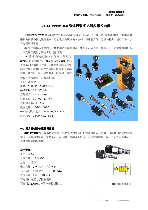
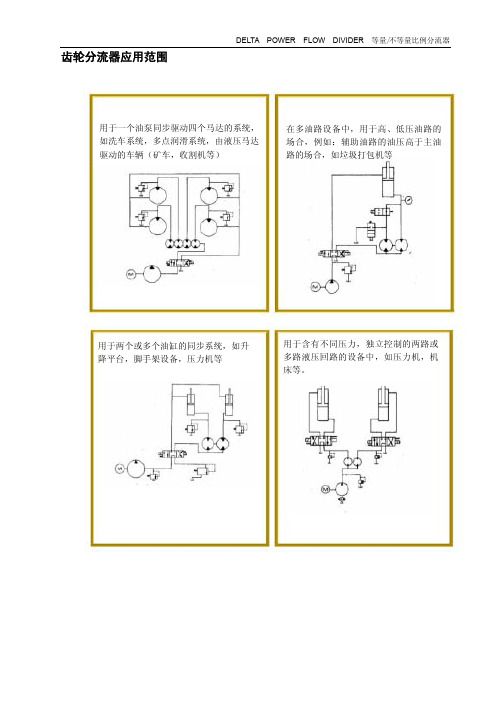
齿轮分流器应用范围用于一个油泵同步驱动四个马达的系统,如洗车系统,多点润滑系统,由液压马达驱动的车辆(矿车,收割机等)用于两个或多个油缸的同步系统,如升降平台,脚手架设备,压力机等用于含有不同压力,独立控制的两路或多路液压回路的设备中,如压力机,机床等。
在多油路设备中,用于高、低压油路的场合,例如:辅助油路的油压高于主油路的场合,如垃圾打包机等分流器固定排量Delta Power齿轮分流器有两种,固定排量的等量分流器以及不等量比例分流器。
它将主油路的油等量或不定量比例分流,变成两路或多路,每一路压力互不干扰,高低取决于外界负载的大小。
该元件是由一系列相互耦合的齿轮泵和齿轮马达组成。
每一片具有泵或马达的功能。
整个元件有一个共同的进油口和各自独立的出油口。
高压油由油泵提供给分流器,分流器只对进油口的液压油起分配作用,不能向油液提供能量,如果分配器每组阀片的尺寸相同,则进油口的高压油将被每个阀片等量分流,如果分配器每组阀片的尺寸不同,则根据每组阀片的几何排量的不同,输出流量也会不同,排量越大的阀片,输出的流量也越大,即几何排量与其输出流量成正比。
由于分流器是一个排量固定的设备,故外界负载压力及油液粘度的变化对其性能影响很小,当然,由于存在容积效率及机械效率的问题,对其精确分流会有轻微的影响。
在性能参数列表中,我们将给出每片阀的允许平均流量误差。
常用关系式:如果不考虑任何损失,则有下面流量关系式:Q i=Q1+Q2+….+Q n;上式的Q i是流入分流器的总流量,Q1Q2….Q n为每组阀片输出流量。
如果不考虑任何损失,则有下面功率关系式:P i Q i=P1 Q1+P2 Q2+….+P n Q n;上式的P i是分流器的入口压力,P1P2….P n为每组阀片出口压力。
在包含不同数目或不同排量的阀片的分流器中,有关系式:P i =(P1 Q1+P2 Q2+….+P n Q n)/ Q i;在实际应用时,还必须考虑分流器的压降及内泄漏影响。
压降主要受油液流量和粘度影响,分流器压降△P p可近似由下式表示:(n为阀片数量)ΔP p≈(6 Q i/n)+25分流器的实际进口压力P ia由下式表示:P ia =(P1 Q1+P2 Q2+….+P n Q n)/ Q I+ΔP p内泄漏量主要受油液粘度、油压及油液清洁程度等因素影响,内泄漏量可由下表粗略估计:排量内泄漏每片最大流量型号(升/转/片)(升/分/0.7Mpa)(升/分)PM20.001780.11 6.5PM60.00520.1518P210.00670.2323.5P230.01150.2639.7P250.0160.356.8P260.020.3870P270.0240.4283.3P430.0390.57132.5P470.0640.83189.3每组阀片输出流量主要受内泄漏大小的影响,而内泄漏大小主要取决于负载压力的大小。
综上所述,系统性能由以下因素决定:1、根据所需流量和压力大小选择分流器。
,输入油流量将根据每组阀片的排量被成比例的分配,分别从各自阀片的油口输出。
2、分流器压降:ΔP p≈(6 Q i/n)+253、分流器输入压力:P ia =(P1 Q1+P2 Q2+….+P n Q n)/ Q I+ΔP p4、每组阀片的压降ΔP1ΔP2….ΔP n由公式ΔP n= P ia- P n计算。
由每组阀片的压降可算出每组阀片的内泄漏量。
5、实际输入每组阀片的流量等于阀片的输出流量加内泄漏量,即Q na=Q n+S n。
上面公式和描述可用来计算分流器所能达到的效果。
须强调的是,如果没有独立的研究、评估和试验,请不要在一些特殊场合应用,以免造成仪器失灵,物品损坏及人身伤亡事故。
两路等量分流器将一个油泵的输入流量均等地分成两路输出。
两个齿轮副安装在一根传动轴上。
PM2 & PM6规格片数最大输入流量(升/分)每片无载排量(升/转)内泄漏量(升/0.7Mpa)最大冲击压力(Mpa)额定压力(Mpa)“A”尺寸(mm)片间允许最大压差(Mpa)PM2 2 13 0.00178 0.098 17.5 14 97.3 10.5 PM6 2 36 0.0052 0.144 14 10.5 119.9 7P23 2 79.5 0.0115 0.257 14 10.5135.1 7 P27 2 166.5 0.024 0.428 14 10.5174.2 7 P43 2 265 0.039 0.51 14 10.5 196.9 7P47 2 378.5 0.064 0.795 14 10.5 235 7多路等量分流器由几个等排量,相对独立的阀片叠加在一起组成,将输入流量等量地分成三路或更多路输出。
每个齿轮副和传动轴都单独安装,采用滚针轴承支撑。
PPM2规格片数最大输入流量升/分每片无载排量升/转内泄漏量L/0.7Mpa冲击压力(Mpa)额定压力(Mpa)“A”尺寸(mm)“B”尺寸(mm)“C”尺寸(mm)“D”尺寸(mm)片间允许最大压差(MPa)PPM2 4 26.5 0.00178 0.098 14 10.5 7 P23-60 3 119 0.0115 0.257 14 10.5 18.2 60.7 65 224.3 7 P23-59 4 159 0.0115 0.257 14 10.5 18.2 60.7 65 289.3 7 P23-58 5 199 0.0115 0.257 14 10.5 18.2 60.7 65 354.3 7 P23-57 6 238 0.0115 0.257 14 10.5 18.2 60.7 65 419.4 7 P27-60 3 250 0.024 0.428 14 10.5 37.8 80.3 84.6 283.5 7 P27-59 4 333 0.024 0.428 14 10.5 37.8 80.3 84.6 368 7 P27-58 5 416 0.024 0.428 14 10.5 37.8 80.3 84.6 452.6 7 P27-57 6 499 0.024 0.428 14 10.5 37.8 80.3 84.6 537.2 7多路等量分流器由几个等排量,相对独立的阀片叠加在一起组成,将输入流量等量地分成三路或更多路输出。
每个齿轮副和传动轴都单独安装,采用滚针轴承支撑。
PM2规格片数最大输入流量升/分每片无载排量升/转内泄漏量L/0.7Mpa冲击压力(Mpa)额定压力(Mpa)“A”尺寸(mm)“B”尺寸(mm)“C”尺寸(mm)片间允许最大压差(MPa)PM2-60 3 20 0.00178 0.064 17.5 14 145 173.5 195.8 7 PM2-59 4 26.5 0.00178 0.064 17.5 14 179.6208 230.4 7 PM2-58 5 33.3 0.00178 0.064 17.5 14 214 242.6 264.9 7 PM2-57 6 39.7 0.00178 0.064 17.5 14 248.7277.1 299.5 7 PM6-60 3 54.1 0.005 0.095 14 10.5 179 207.8 230.1 7 PM6-59 4 71.9 0.005 0.095 14 10.5 225.3253.7 276.1 7 PM6-58 5 90.1 0.005 0.095 14 10.5 271.3299.7 322.1 7 PM6-576 107.9 0.005 0.095 14 10.5 317.2343.2 368 7可选增上面的混合流量分流器表中的任一种阀片,最多组合不超过6片(详见混合比例分流器)。
注意:当计算内泄漏量时,可应用上述数据来反映每片进口和出口的压差。
由于正常的制造压差,在负载均衡的状态下,精度应<±1%。
)混合流量分流器由下列表中不同排量的阀片组合而成(最多不超过8片)。
一路输入,多路比例输出。
每组齿轮副和传动轴由单独的滚针轴承支撑。
规格片 数最大输入流量升/分每片无载排量升/转内泄漏量 L/0.7Mpa冲击压力(Mpa)额定压力(Mpa)“A”尺寸(mm)最高转速 RPM最低转速 RPM片间允许最大压差(MPa )PM1 1 3.79 0.0011 0.057 17.5 14 3.56 3500 500 7 PM2 1 6.8 0.00178 0.064 17.5 14 5.84 3500 500 7 PM4 1 11.4 0.0031 0.076 14 10.5 7.87 3500 5007 PM6 1 18.2 0.0052 0.09514 10.5 10.2 3500 5007 PM8 1 13.6 0.0076 0.114 14 10.5 13.5 3500 5007订货说明:订货时,若分流器由两片PM1,一片PM6,一片PM8组成,则订货号为:PM1-1-6-8;若分流器由3片PM4组成,则订货号为:PM4-4-4 )混合流量分流器由下列表中不同排量的阀片组合而成(最多不超过8片)。
一路输入,多路比例输出。
每组齿轮副和传动轴由单独的滚针轴承支撑。
规格片 数 最大输入流量升/分每片无载排量升/转内泄漏量 L/0.7Mpa冲击压力(Mpa)额定压力(Mpa)“A”尺寸(mm)最高转速 RPM最低转速 RPM片间允许最大压差(MPa )P21 1 23.5 0.0067 0.227 14 10.5 10.6 3500 5007 P23 1 39.7 0.0115 0.257 14 10.5 18.2 3500 500 7 P25 1 56.80.0161 0.31414 10.5 25.4 3500 5007 P26 1 70 0.0201 0.371 14 10.5 31.8 3500 500 7 P27 1 83.30.0240 0.42814 10.5 37.8 3500 5007PM系列多路等量分流器-配置安全溢流阀多路等量分流器由几个等排量,相对独立的阀片叠加在一起组成,将输入流量等量地分成两路或更多路输出。
每个齿轮副和传动轴都单独安装,采用滚针轴承支撑。
PM2RV & PM6RV规格片数最大输入流量升/分每片无载排量升/转内泄漏量L/0.7Mpa冲击压力(Mpa)额定压力(Mpa)“A”尺寸(mm)最高转速RPM最低转速RPM片间允许最大压差(MPa)PM2RV 2 13.25 0.00178 0.098 17.5 14 5.84 3500 500 10.5 PM6RV 2 36 0.0052 0.144 14 10.5 10.16 3500 500 7 PPM2RV 4 26.5 0.00178 0.098 14 10.5 13.46 3500 500 7注:分流器所带溢流阀仅用于分流器自我保护,不能用于系统压力的设定。