分子泵说明书2.2
- 格式:pdf
- 大小:731.42 KB
- 文档页数:21
分子泵离子泵机组概述说明以及解释1. 引言1.1 概述分子泵离子泵机组是一种常用于真空工程领域的设备,主要用于抽取和处理气体。
它由分子泵和离子泵两部分组成,通过联合运行实现更高效的气体抽取和净化。
本文旨在对分子泵离子泵机组进行全面的概述、说明和解释。
1.2 文章结构本文将首先对分子泵离子泵机组进行概述,介绍其工作原理以及机组的各个组成部分。
然后将阐述分子泵离子泵机组在不同应用领域的应用情况,包括半导体制造业、真空冶金以及科学研究等方面。
接着将详细探讨该机组的优点和局限性,包括高真空度和快速抽气能力、低污染和低挥发性气体处理能力,以及高能耗和维护成本较高等方面。
最后,文章将总结以上内容,并展望未来分子泵离子泵机组可能的发展趋势。
1.3 目的本文旨在向读者提供关于分子泵离子泵机组的全面了解。
通过对其工作原理、应用领域、优点和局限性的介绍,读者能够更加清晰地了解该设备在真空工程中的重要性和作用。
同时,本文也旨在启发读者思考分子泵离子泵机组未来的发展方向,以促进相关技术的突破和创新。
2. 分子泵离子泵机组概述2.1 分子泵的工作原理分子泵是一种利用分子流冲击吸附在表面上的气体分子,从而将气体抽出真空容器的高效真空设备。
其工作原理主要包括以下几个步骤:首先,在分子泵内部,通过旋转的转子将气体分子带到排气口,并且在排气口处形成一个密闭区域。
然后,在这个密闭区域内,分子泵内壁上涂有吸附剂,如涂有铯或冷阴极等金属材料。
当气体分子与涂层接触时,它们将被吸附并停留在表面上。
接着,在高速自由径向动能的影响下,排气回流到真空容器的那些吸附在内壁上的气体分子,会再次获得较大能量并溅射到其他表面上。
这样循环进行下去,持续地将气体分子抽出真空容器。
总结来说,分子泵通过使用旋转转子和涂层材料来抽取和重新释放气体分子,并不断循环这个过程,从而达到高效抽气的目的。
2.2 离子泵的工作原理离子泵是一种利用电场加速,通过离子化和阴极反应来抽取气体分子的高真空设备。
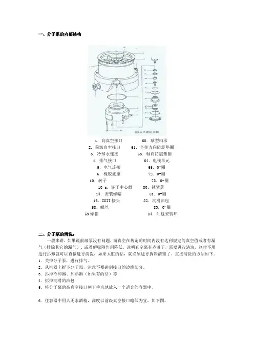
一、分子系的内部结构1.高真空接口 60.球型轴承2.前级真空接口 61.半径方向防震垫圈3.冷却水连接 63.轴向防震垫圈4.排气接口 64.电视单元5.电气连接 65.0-圈6.橡胶底座 72.0-圈10.转子73.0-圈10 a.转子中心毂 80.锁紧著14.安装螺帽 81.0-圈16.USIT接头 82.润滑油包58.螺丝 83.0-圈59螺帽 84.油包安装环二、分子泵的清洗:一般来讲,如果说前级泵没有问题,而真空在规定的时间内没有达到规定的真空值或者有漏气(排除其它的漏气)、或着解吸附作用降低,说明真空泵有点脏了,需要进行清洗,这时不用进行拆卸就可以直接进行清洗,如果太脏的话,就必须进行拆卸清理了。
直接清洗的方法如下:1.关掉分子泵,进行排气。
2.从机器上拆下分子泵,注意不要碰到接口的边缘部分。
3.拆掉冷却器、加热器(如果有的话)等4.拆掉润滑的油包5.将分子泵的高真空接口朝下垂直地放入一个适合的容器中。
6.往容器中用人无水酒精,高度以前级真空接口略低为宜,如下图。
7.上下活动分子泵几次,便于分子泵的定子和转子的叶片清洗,在无水酒精中浸泡大概5~10分钟。
8.换掉无水酒精,加入新的无水酒精,重复前面的工作,最少要重复一次。
9.拿出分子泵。
10.将高真空接口朝上,从垂直慢慢放倒到180度,以便排除磁性轴承中的酒精。
11.用一个网格放在高真空接口上,然后朝下放置,利用一个泵抽大概30分钟左右。
注意接口的密封表面不要损坏。
12.接上前级真空泵,不要开分子泵,利用前级泵抽真空,达到大概10E-1左右,以便完全清除分子泵中残留的无水酒精。
13.更换真空泵中的真空油,接上分子泵开始工作。
注意第一次抽真空时是比较慢,这是因为分子泵中有残留的酒精,属于正常情况,不必忧虑。
三、驱动马达的检查驱动马达的检查可以用两种方法,一个是带带驱动单元TCP时用示波器看波形。
一个是不带驱动器检查线路。
带驱动单元TCP的方法操作,这里要注意一点,就是探针式的霍尔传感器是没有0电位的,所以在用示波器的时候将0V线拔掉。
目录1.概述 (1)1.1目的及简要说明1.2设计和运行方式1.2.1设计1.3转换装置PN300/PN2001.3.1说明1.4技术数据1.4.1采用汽油发动机的压缩机装置1.4.2采用三相电动机的压缩机装置1.4.3采用交流电动机的压缩机装置1.5空气流程图2.润滑 (9)2.1油面高度检查2.2油的类型2.2.1合成润滑油2.2.2矿物润滑油2.2.3油型号的变更2.3换油3.进气过滤器 (11)3.1说明3.2进气过滤器维修3.3伸缩式进气管4.中间分离器 (13)4.1功能介绍4.2中间分离器维修5.过滤器系统P21 (14)5.1用途及概要介绍5.2滤筒安全孔5.3寿命5.4过滤器维修说明5.5更换时间规定5.6冷凝水排放5.7滤筒更换6.保压阀 (21)6.1说明6.2维修7.安全阀 (22)7.1说明7.2维修7.2.1运行检查7.2.2放泄压力检查8.压力计 (23)8.1说明8.1.1终压压力计8.2维修9.阀门 (24)9.1功能介绍9.2初次运行检查9.3更换阀门的一般性气说明9.4第1级的阀门的更换9.5第2级的阀门的更换9.6第3级的阀门的更换10.压缩机驱动系统 (29)10.1概述10.2对驱动皮带进行检查10.3V-皮带张紧度调节11.电气系统 (31)11.1驱动电动机11.1.1电动机保护开关12.冷却系统12.1概述 (33)13.安全规程 (33)13.1概述13.2安全规程(德国)14.运行位置 (41)14.1室外位置14.2室内位置14.3电气装置14.4运行14.4.1运行的准备工作14.4.2装置起动14.5充灌程序14.5.1概述14.5.2压缩机装置的清理工作14.5.3气瓶的连接14.5.4充灌气瓶14.5.5卸下气瓶14.6关闭停机程序15.维修 (49)15.1维修记录15.2维修时间间隔15.3维修计划表15.3.1运行小时数的记录16.存放、保护 (56)16.1准备工作16.2压缩机重新使用17.修理说明 (57)17.1概述18.故障消除 (57)19.表格 (58)19.1拧紧力矩值19.2拧紧次序19.3润滑表19.4换算表巴-psi19.5换算表psi-巴19.6温度换算表19.7其它各种换算表20.附录 (66)图1采用汽油发动机的压缩机装置图2采用电动发动机的压缩机装置图3转换装置图4空气流动图图5油尺标记图6进气过滤器图7中间分离器图8过滤器系统P21图9安全孔图10保压阀图11终压安全阀的通气图12阀门动作图13第1级的阀头图14第2级的阀头图15第3级的阀头图16第3级压力阀的取下图17V-皮带张紧度检查图18V-皮带轮调节图19电动机保护开关图20电动机保护开关图21气瓶的连接图22国际通用的充灌连接器图23气瓶的充灌图24取下气瓶图25电动机保护开关图26拧紧次序附录空气流程图KB62482-993气动部件表KB65417-993电动机保护开关原理图KB72915-992电气部件表KB56344-992部件清单TJ-2/0润滑油表KB70851-994变更通知变更次数变更日期0 第1版,1993.21 1994.1Junior使用手册1.概述1.1 目的及简短说明Junior呼吸用空气压缩机是可把压缩气瓶充灌到225巴(3200psi)或330巴(4700psi)压力的一种整套装置。
6.安装6.1 注意事项分子泵不能用于抽除液体或者带有粉尘、固体颗粒的气体;除了耐腐蚀型泵以外,其他任何分子泵不能用于抽除腐蚀性气体,耐腐蚀型泵在抽除腐蚀性气体时,必须给分子泵的保护气体入口连续通惰性保护气体如氮气等,且泵油使用我公司提供的专用耐腐蚀分子泵油。
确认分子泵与电源相配套。
每种泵都只能使用本说明书中规定的与之匹配的电源供电,否则造成的损失,本公司概不负责。
确认安装环境必须满足如下条件:1)泵体表面径向和轴向磁场强度均不得大于3mT(30Gs);2)环境放射性强度<105rad;3)环境温度为5~40℃;4)空气相对湿度:≤85%;5)电压:220±22V,频率:50±1Hz;6)海拔:≤3000米。
安装前应检查分子泵运输中是否被损坏:打开泵高真空端法兰盖板,戴好手套,拨动涡轮转子,应转动灵活,无异常现象。
若存在异常现象,应及时通知我公司,不得自行处理,否则由此带来损失我公司概不负责。
不允许将分子泵长期置于大气状态下存放,在打开进气口和排气口盲板时,应注意真空卫生要求,严禁杂物、灰尘等落入泵内。
安装环境应符合技术要求和真空卫生要求。
6.2 连接安装6.2.1真空联接分子泵的进气口和排气口法兰采用国际标准见表4分子泵技术数据表,尺寸见分子泵安装简图和分子泵排气口简图。
注意:法兰密封面不得有划痕、刀口不得磕碰。
泵的联接可利用进气口法兰吊装或将泵置于基座平面上,但F-400/4200不建议吊装,若一定要吊装必须用活套法兰(订货时单独订购)固定。
分子泵的进气口法兰通过金属波纹管与系统联接时,分子泵必须固定。
为保护分子泵转子,防止外界物质落入泵内,可在泵口装上防护网,但装入此网后,抽速约降低15%左右。
前级泵与分子泵的联接应采用具有减震效应的金属波纹管,管路上应装有隔断放气阀,作为停机时对前级机械泵放气。
放气阀可选用手动阀或电磁阀。
放气过程的操作请参照停机部分。
为保护泵体真空卫生,防止潮湿,放气时,可通氮气或干燥空气。
分子泵自动停机的原因1. 引言1.1 分子泵的作用分子泵是一种主要用于真空技术领域的设备,其作用是通过运行机械或分子运动来实现真空抽取和排气。
分子泵可以将气体从一个相对较高的压力抽取到一个更低的压力,使得系统内气体的压力达到所需的真空度。
这对于许多科学实验、制造过程和其他应用来说都非常重要。
通过分子泵,可以实现对真空系统的精确控制,以保证实验或生产过程中所需的环境压力。
在科学研究中,例如在材料科学、化学、物理等领域,通常需要在低压力环境下进行实验以减少气体干扰或实现特定反应条件。
而在半导体制造或光学设备制造等领域,分子泵则能够保证设备内部的洁净度和稳定性,确保产品质量和性能。
分子泵在不同领域中都发挥着重要的作用,为各种实验、制造过程提供了必要的真空环境。
保证分子泵正常运行,确保其自动停机的原因及时排查并解决,对于保障实验和生产的顺利进行至关重要。
1.2 分子泵自动停机的重要性分子泵的作用是通过抽真空的方式将容器内的气体抽出,从而创造出一个低压的环境,适用于各种实验和生产工艺中。
而分子泵自动停机的重要性不容忽视,它直接关系到设备的稳定运行和工作效率。
分子泵是实验室和生产线上必不可少的设备之一,一旦分子泵出现问题导致停机,将会导致整个实验或生产过程中断,影响工作进度。
分子泵运行过程中如果出现问题不及时停机,可能会造成设备损坏,导致更严重的后果。
分子泵自动停机也是保护设备和操作人员的一种重要手段,及时发现问题并停机可以避免可能的安全事故发生。
为了确保分子泵的正常运行和设备的安全可靠性,及时排查分子泵自动停机的原因并解决问题是十分重要的。
只有这样,我们才能保证分子泵能够稳定运行,为实验和生产提供持续稳定的支持。
2. 正文2.1 供电故障导致停机供电故障是导致分子泵自动停机的常见原因之一。
当分子泵所连接的电源供电故障时,泵无法正常运转,导致停机。
供电故障可能是由于电源线路故障、电源变压器故障、电源开关故障等原因造成的。
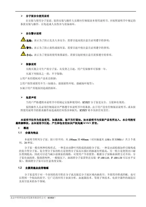
企业通过ISO 9001质量管理体系认证分子泵全系列 使用说明书¾分子泵安全使用说明在安装与使用分子泵前,泵的安装与操作人员都应仔细阅读本使用说明书,并按照说明书中规定的条款安装与操作,以免造成人员伤害与设备损坏。
¾安全警示说明危险:表示为了防止危及人身安全,需要引起高度注意且必须遵守的事项;警告:表示为了防止损伤或损坏泵,需要引起中度注意且必须遵守的事项;小心:表示为了使泵的使用效果最佳,需要引起轻度注意且需要遵守的事项。
¾保修说明凡购买我公司生产的分子泵,从发货之日起,用户凭保修单可保修一年。
凡属下列情况之一的,不予保修:1)用户未经授权对产品私自拆卸;2)用户保管或使用不当(如撞击、强放射性环境、强磁场环境等);3)属于用户其他原因造成的损坏。
¾免责声明当用户严格遵照本说明书中的规定安装和使用时,KYKY分子泵是安全、方便和有效的。
泵的操作人员必须仔细阅读并严格遵守本说明书中的条款。
由于用户没有仔细阅读说明书、或未按照使用说明书的要求操作而造成的任何伤害和损失,KYKY将不负担任何责任。
本说明书仅作为信息使用,如遇改版,恕不另行通知。
如本说明书与实际产品有所出入,本公司拥有最终解释权。
由本说明书引起、产生和包含的知识产权均属KYKY所有。
1概述1.1 分类与特点本说明书所列分子泵,按口径不同,从100mm到400mm(对应抽速从110l/s到3500l/s)共5个系列,12种泵。
分子泵一般有两种结构形式,一种是由动静叶列组成的涡轮分子泵,一种是由涡轮级加牵引级构成的复合型分子泵。
复合型分子泵的特点是使得分子泵高压强区的抽速有所提高,另一特点是使得出口耐压得到提高,因此可以适当减小前级泵的规格,可使用户节省投资。
根据分子泵轴承润滑方式不同,分子泵有油润滑、脂润滑两种。
一般情况下,油润滑分子泵需竖直安装(F-100/110可以水平安装),脂润滑分子泵可以任意角度安装。
263-13485This power supply unit differs slightly from the standard specification.This instruction manual contains the differences from the standardspecification.Prior to using this product, be sure to read this instruction manual.Additionally, be sure to read the instruction manuals for the turbo molecularpump and its power supply unit.Keep the "Instruction Manual" in a safe and accessible place.Semiconductor Equipment DivisionMagnetic Bearing Turbo Molecular Pump Model TMP-V2304LM (PB)Instruction Manuali Magnetic Bearing Turbo Molecular PumpInstruction Manual IntroductionThank you for choosing the Turbo Molecular Pump. Please read the instruction manual carefully before using Turbo molecular pump, and save the instruction manual for future reference.This turbo molecular pump ( TMP-V2304LM (PB) ) differs slightly from the standard specifica-tion ( TMP-V2304LM ). Only a paragraph different from the standard specification is shown in this manual. Please read the INSTRUCTION MANUAL for standard specification in a differ-ent way as follows.(NOTE) Information in this document is for specifications of beta site model. This informationis subject to change without notice.Copyrights and DisclaimersThis document is copyrighted by Shimadzu Corporation. Please refrain from reproducing or copying part or all of this document without permission from Shimadzu.In an effort to improve the product, this document may be revised in the future without notice.Every effort has been made to prepare an accurate and complete manual, but if an error or omission should be discovered, revisions might not be possible immediately.Shimadzu does not take responsibility for any effects that may result from the use of this manual.Copyright 2008 Shimadzu Corporation.All rights reserved.©This page is intentionally left blank. ii263-13485Table of contents iiiMagnetic Bearing Turbo Molecular PumpInstruction Manual Table of contentsIntroduction1.2Descriptions. . . . . . . . . . . . . . . . . . . . . . . . . . . . . . . . . . . . . . . 11.2.1Exterior . . . . . . . . . . . . . . . . . . . . . . . . . . . . . . . . . . . . . . . . . . . . . . 11.2.2 Standard Accessories. . . . . . . . . . . . . . . . . . . . . . . . . . . . . . . . . . . 22.1Pump Main Unit . . . . . . . . . . . . . . . . . . . . . . . . . . . . . . . . . . . . 32.2Control Panel. . . . . . . . . . . . . . . . . . . . . . . . . . . . . . . . . . . . . . 42.3External I/F Panel . . . . . . . . . . . . . . . . . . . . . . . . . . . . . . . . . . 54.1 Standard Specifications for Pump Unit. . . . . . . . . . . . . . . . . . 76.7Remote-Control Connector . . . . . . . . . . . . . . . . . . . . . . . . . . . 96.7.1Specification . . . . . . . . . . . . . . . . . . . . . . . . . . . . . . . . . . . . . . . . . . 96.7.2 Pin Assignment. . . . . . . . . . . . . . . . . . . . . . . . . . . . . . . . . . . . . . . 106.7.3Connector . . . . . . . . . . . . . . . . . . . . . . . . . . . . . . . . . . . . . . . . . . . 11iv This page is intentionally left blank.263-13485Table of contents1.2 Descriptions11Magnetic Bearing Turbo Molecular PumpInstruction Manual 1.2 Descriptions 1.2.1Exterio rFig.1-1 TMP-V2304LM (PB )Inlet FlangeISO250BSECTION 121263-134851.2.2 Standard Accessories NoDescription This specification Standard specifcation 1Model TMP-V2304LM (PB)TMP-V2304LM 2Instruction ManualP/N:263-13476 manual for TMP-V04 series serial communica-tion P/N:263-13475 manual for TMP-V2304LM 3Exclusive InstructionManualP/N:263-13485 This manual P/N:263-13477 Manual for TMP-V04 series PROFIBUS option N.A.4Accessory CD-ROM P/N:263-40195 For PROFIBUS option N.A2.1 Pump Main Unit3Magnetic Bearing Turbo Molecular PumpInstruction Manual 22.1 Pump Main UnitFig.2-1 Pump Main Unit(1) INLET FLANGE. . . . . . . . . . . . . Inlet flange, joint the turbo molecular pump,ISO250B,(2) PORT FOR GAS PURGE . . . . . Gas purge adaptor port(3) OUTLET FLANGE. . . . . . . . . . . Outlet flange, connect a backing vacuum pump or its related pipe connection, KF40.(4) COOLING WATER PIPELINE. . Cooling water pipe connector, Rc1/4(5) WATER VALVE. . . . . . . . . . . . . For protection from dew.This valve is normally closed valve. (opened when energing, and closed when not energing)(6) CONTROL PANEL . . . . . . . . . . AC Input connector,Power Switch,and local controlswitch (see Section 2.2 "Control Panel")(7) External I/F PANEL . . . . . . . . . . Communication Interface (see Section 2.3 "External I/FPanel")SECTION 242263-134852.2 Control Panel Fig.2-2 Outline view of control panel(1) AC INPUT connecter . . . . . . . . . . . Power cable receptacle(2) POWER Switch . . . . . . . . . . . . . . . Power switch(3) START/STOP button . . . . . . . . . . . Press to acceleration or decelerationDuring LOCAL MODE, control by maintained push(4) RESET button. . . . . . . . . . . . . . . . . When occur ALARM or WARNING, After remedying thecause of the ALARM, An abnormal state is released bypressing button. By maintained push, REMOTE MODEand LOCAL MODE are changed(5) POWER lamp. . . . . . . . . . . . . . . . . This lamp lights or blinks while energizing.lights :REMOTE MODEblinks :LOCAL MODE(6) ROTATION lamp . . . . . . . . . . . . . . Operation indicator lamp indicating that the pump's rotor isrunning (green)(7) STATUS lamp . . . . . . . . . . . . . . . . Operation indicator lamp indicating that the pump'soperation status (green ・orange )green/blink :Acceleratinggreen/lights :Rotational speed reaches 80% rated value.orange/lights :ALARM occurs(8) NET lamp . . . . . . . . . . . . . . . . . . . . Operation indicator lamp indicating that PROFIBUScommunication status (green ・orange )green/blinks :Confirming internal connectiongreen/lights :Established Internal connection normallyorange/blinks :Error in PROFIBUS communicationorange/lights :Error in internal communication2.3 External I/F Panel5Magnetic Bearing Turbo Molecular PumpInstruction Manual 22.3 External I/F PanelFig.2-3 I/F Panel(1) REMOTE connector . . . . . . . . . . . . Connect by Remote-control connectorRefer to Section 6.7 "Remote-Control Connector".(2) PROFIBUS connector. . . . . . . . . . . Connect by PROFIBUS communicationRefer to separate manual for PROFIBUS option.(3) SERIAL connector . . . . . . . . . . . . . Connect by RS-232C or RS-485 communication.(4) VALVE connector . . . . . . . . . . . . . . Water valve connectorSECTION 22This page is intentionally left blank. 6263-134854.1 Standard Specifications for Pump Unit7Magnetic Bearing Turbo Molecular PumpInstruction Manual 44.1 Standard Specifications for Pump Unit Turbo molecular pumpmodel TMP-V2304LM (PB)TMP-V2304LMCommu-nication Contact REMOTE (D-sub HD 15pin Screw lock size M2.6)Input : START / STOP / RESET / LOW SPEED Output :ROTATION/ NORMAL/ ALARM / WARNING REMOTE(D-sub 37pin femaleScrew lock size M2.6)Input : START / STOP /RESET / LOW SPEEDOutput :ROTATION / ACC. /BRAKE /NORMAL /REMOTE /ALARM /WARNINGPROFIBUS PROFIBUS-DPV0( D-sub 9pin female Screw lock size M2.6)N.A.Serial RS-232C /RS-485( D-sub 9pin maleScrew lock size M2.6)SECTION 44This page is intentionally left blank. 8263-134856.7 Remote-Control Connector9Magnetic Bearing Turbo Molecular Pump Instruction Manual 66.7 Remote-Control Connector6.7.1 SpecificationTable 4-1 Start/Stop According to Remote-Control SignalsThis TMP is provided with remote-controlconnector for connection with remoteoperation, ALARM signals, etc. For connection with this connector, cable with shield is necessary. The shield of the cable should be connected to case For remote-controlled operation, need to change to REMOTE MODE.Fig.4-1 Remote-Control CircuitSECTION 6106263-134856.7.2 Pin Assignment Table 4-2 Remote-Control Signals (Note 1) "STOP" signal is prior to "START" signal (Note 2)It is possible to change movement by remote-control signal settings of serial communication (Note 3) Don't connect any pins other than specified above (Note 4) It takes six seconds until it comes to show that this signal is correct, after POWER switch is turned on (Note 5)One Reset signal is input each time the contacts close. Repeatedly short and open the contacts to input multiple Reset Pin No.Operation Electric spec Input START 14Starting operation on GND and short-circuiting (Note 1)Contact Input STOP 12Stopping operation on GND and short-circuiting (Note 1)RESET 11Resetting operation on GND and short-circuiting LOW SPEED 13Variable speed operation on GND and short-circuiting GND 15GND Out-put ROTAION 27During rotation (17)-(19):open →close ( make contact )(18)-(19):close →open ( break contact )Contact Output Contact capacity (resistanc e load)DC30V 1 A NORMAL 16During rotational speed is more than 80% rated value (1)-(6) open →close( make contact )ALARM 385Against ALARM(Note 6)(3)-(8):open →close ( make contact )(5)-(8):close →open ( break contact )WARNING 49Against WARNING(Note 6)(4)-(9):open →close ( make contact )6.7 Remote-Control Connector11Magnetic Bearing Turbo Molecular PumpInstruction Manual 6(Note 6)Actions can be changed via communication operations.I f set to EI-03, remote control functionality will be the same as for EI-Dxx03M seriespower supply units for Shimadzu turbo molecular pumps.If set to SEMI E74, remote control functionality will comply with SEMI Standard E74"Specification for Vacuum Pump Interfaces". The connector shape and pin configuration details will conform to the standard as well.6.7.3 Connector Fig.4-2 Arrangement of Remote-Control Connector Pins(Figure where connector of panel was viewed from the front )Signal Description Pin No.ALARM ⑤-⑧③-⑧EI-03 (Note 1)Alarm occurredOpen Open ClosedPower OFF and no alarm Closed OpenSEMI E74 (Note 2)Power OFF and active alarm Closed OpenNo alarm Open ClosedWARNING ④-⑨EI-03 (Note 1)Warning occurred ClosedPower OFF and no alarm OpenSEMI E74 (Note 2)Power OFF and active warning OpenNo alarm ClosedSTOP REMOTE ONLY “STOP ” signal (open between (12) and (15)) is enabled only whenremote control is enabled.REMOTE & RS-XXX “STOP ” signal (open between (12) and (15)) is enabled by priorityeven during RS-232C and RS-485 operation. Use this setting such aswhen using hardware interlock.SECTION 66No text 12263-13485FEM9M-E0122-02 TMP overhaul / repair request formPlease fill out this request form and attach to the product before you send back to Shimadzu service centerfor overhaul or repair service. We ask that you fill out this form completely to expedite the service and return shipment. Please mark the item box, and fill out the blank.(1) Product□Pump (TMP- )s/n ( )□Controller (EI- )s/n ( )(2) Request□Overhaul□Repair□Other(3) Details(4) Alarm code(If status lamp indicates, No is )(5) Date of failure occurrence ( ) (6) Date for return shipment request ( )(7) Date of TMP operation start ( ) (8) Date of previous delivery ( )(9) Parts exchange If any parts exchange is recommended due to the excess of usage recommendation period,recommendation□(a) Please exchange the parts.□(b) Don't exchange unless any deterioration is found in the inspection.In case of (b), even if any failure occurs with the cause of partsfor which customers choose continuous usage, it's out of warranty.Especially at rotor, it causes the material deterioration which even the fluorescent penetranttest can't detect after long term running. For this reason, periodical exchangeis recommended in order to use the rotor safely.(10) Declaration Components which have been contaminated by hazardius substrates will not be acceptedof contamination or served without written evidence of decontamination.- Equipment process □Etch □PVD □CVD □Others ( )- Materials the equipment has been exposed to ( )(Eched material, CVD/PVD target, etc)- Gases the equipment has been exposed to□Air, Nitrogen, etc ( )□Reactive/active gas ( )□Inert gas such as helium, etc ( □Virulent gas ( )□Corrosive gas ( )□Others ( )- Is it hazardous to human ?□Yes□No- Is there color change or adhesion at inlet or outlet flange ?□Yes□No(If yes, please let us perform TMP cleaning at additional charge to keep appropriate performance.- Precaution and procedure for decontamination in case it's necessary at Shimadzu.( )(11) Gas purge□Used ( sccm)□Not usedI declare that the TMP being returned doesn't contain any amount of hazardous residuesthat exceed the permissible exposure limits on the MSDS and that the informationprovided above is complete and accurate.Date ( ) Company ( )Job title ( )Name ( )Signature ( )Phone ( )Fax ( )SHIMADZU CORPORATION. Internatinal Marketing Division3. Kanda-Nishikicho 1-chome, Chiyoda-ku, Tokyo 101-8448, JapanPhone:81(3)3219-5641 Fax:81(3)3219-5710SHIMADZU SEMICONDUCTOR EQUIPMENT USA2340-C Walsh Avenue, Santa Clara, CA95051, U.S.A.Phone:1(408)566-0960 Fax:1(408)566-0961 E-mail:tmp@KRATOS ANALYTICAL LTD.Wharfside, Trafford Wharf Road, Manchester M17 1GP EnglandPhone:44(161)888-4400 Fax:44(161)888-4402 E-mail:vacuum@SHIMADZU (ASIA PACIFIC) PTE LTD.16 Science Park Drive #01-01 Singapore Science Park, Singapore 118227, Republic of Singapore Phone:65-6778-6280 Fax:65-6779-2935SHIMADZU INTERNATIONAL TRADING (SHANGHAI) Co., LTD.Block E, No.570 West Huaihai Road, Shanghai, 200052Phone:86(21)2201-3888 Fax:86(21)2201-3666URL 。
企业通过ISO 9001质量体系认证FJ-1200涡轮分子泵机组使用说明书目录一、概述 (1)二、机组主要配置 (1)三、机组技术参数 (1)四、系统结构 (2)五、安装 (2)六、操作规程 (3)七、常见故障及处理方法 (5)八.注意事项 (5)九、保养、维护 (5)一、概述FJ-1200C非标涡轮分子泵机组是一台清洁的高真空获得设备。
此设备是根据真空知识原理,利用机械泵、涡轮分子泵组合成的真空获得系统,具有启动时间快、真空度高、操作方便等特点。
广泛应用于表面分析、加速器技术、等离子体技术、电真空器件制造及真空的各个领域。
设备的具体组成主要包括真空测量系统、真空室、阀门及真空管路、泵体加热控制、电器控制系统、水冷却保护控制等。
二、机组设备主要配置名称数量FF200/1200C分子泵(刀口) 2RVP-12机械泵 2KF40电磁隔断放气阀 2三、技术参数极限真空度(泵口):≤1×10⁻⁷Pa真空系统漏率:≤5×10⁻⁹PaM3/S电源电压:220V±10/50Hz冷却方式:水冷(冷却水温度≤25℃)设备总功率:1.6Kw设备环境使用温度:5-40℃设备环境使用湿度:≤80%四、系统结构系统的工作原理图如下图所示,主要分为机械部分、气路系统和电器部分。
系统工作原理图五、安装拆开包装箱,将设备从箱体中取出,检查设备有无损坏,将设备的电源线接好,将地线与设备机壳连接。
如果是三相供电方式,第一次通电时需要观察机械泵的相序,打开总电源开关,观察分子泵机组电源的相序指示灯,如果相序指示灯亮表明机械泵相序正常;如果相序指示灯不亮表明机械泵相序不正常。
关掉总电源,将三相电源线中的任意两相对调,以确保机械泵相序正确。
危险!在接入供电电源时,务必要确认是否和设备要求的电源电压相符。
在调整相序时,务必将总电源关掉,以确保人身安全。
安装时应注意以下几点:1、设备安装应平地上,竖直方向上与垂直方向夹角小于5度。
TURBOLAB 80 Turbomolecular pump system with dry compressing backing pumpOperating Instructions GA501591_002_A2Material number501591VxxxContents1D scription 31.1Ordering Information 31.2Supplied Equipment 31.2.1Pump System Components 31.2.2Accessories 31.3Technical Data 42Conn ctions 42.1Conforming Utilisation 53Op ration 63.1Electrical Connection 63.2Switching the System on 73.3Changing the Default Settings of the System 73.3.1 Selecting the HV Gauge Head 83.3.2 Selecting the Forevacuum Gauge Head 93.3.3 Selecting the Language 93.4Commissioning the System 103.4.1 Changing the Display Settings 113.4.2 Pressure History 113.4.3 Operating Hours 113.4.4 Venting Valve 123.4.5 Pressure Units 133.5Shutting the System Down 133.6Operating Information 134Spare Parts 145Options 141 DescriptionDescribed in these Operating Instructions is the equipment and operation of the turbomolecular pump system TURBOLAB 80.1.1 Or d ering InformationTURBOLAB 80, DN63ISO-K 501591V1xyz*TURBOLAB 80, DN63CF 501591V2xyz**xyz indicate the precise version of the system together with the possible options.1.2 Supplie d EquipmentTURBOLAB 80Mains cord 230V/1ph/50HzOperating Instructions for the pump systemOperating Instructions for the turbomolecular pumpInlet screen for the turbomolecular pump1.2.1 Pump System Componentsx Turbomolecular pump SL80x Frequency converter TURBO.DRIVE 400x24 V DC power supply unitx Diaphragm pumpx Control unit1.2.2 AccessoriesOptional accessories for the pump systems are:x High vacuum gauge ITR90x High vacuum gauge PTR90x Forevacuum gauge TTR91x Venting valve1.3 Technical DataPumping spee d for N2 60 l/sAttainable ultimate pressure range 10-7 mbar *Run-up time for the turbomolecular pump 1.5 minutesPumping speed of the diaphragm pump 0.7 m³/hUltimate pressure of the diaphragm pump 3 mbarMains voltages 100-240V, 1ph,50-60HzMain fuses (at the main switch) 10 ADimensions 255 x 355 x 355 mmAmbient conditionsTemperature 0 – 35°CHumi d ity 5 – 95%,non-condensingWeight 14.5 kg* At ambient temperature 20°C.2 ConnectionsNever expose any parts of the body to the vacuum.The turbomolecular pump must be firmly attached usingbolts.If the pump is not affixed adequately, parts from inside thepump may come loose and fly around should the pumpseize. Never operate the pump system without having flanged it to the vacuum chamber first in the course of a benchtop test, for example.After a mains power failure in the pump may run up automatically as soon as the mains power returns.If the pump has been pumping hazardous gases before, then introduce suitable precautions before opening the intake or exhaust connections.If necessary, wear protection gloves, breathing protection or protective clothing and work under a fume hood.The turbomolecular pump system is not suited for pumping of dusty, aggressive or corrosive media.The turbomolecular pump system must only be uninstalled when not in operation.Accelerating forces must be avoided or reduced to such a level that the rotor unit is not excited by vibrations. In critical applications consult our application department first.The pump must be only opened by persons duly authorised by Leybold.2.1 Conforming UtilisationVacuum pump systems as described in the catalogue are not suited for pumping of:Ŷҏo xygen at levels exceeding the concentration present in theatmosphere,Ŷҏh azardous gases,Ŷҏe asily flammable, explosive or toxic gases,Ŷҏe xtremely aggressive or corrosive mediaŶҏl iquidsŶҏo r solid materials.The operator is responsible for assessing the danger potential of the process media which as to their composition differ from the normal atmosphere.3 Operation3.1 Electrical ConnectionWarningRisk of suffering injury!During all connection work deenergise mains power lines(lockout/tag out). The electrical connections must only beprepared by a trained electrician as, for example, in accordancewith EN 50110-1.The mains connection of the pump system can be found on the right at thebottom on the rear of the pump system. There also the main switch can befound. The main fuse is located behind a cover panel on the main switch.Main switchMains connection Connectionfor the highvacuumgaugeFuses for theturbomolecular pump,forepump and controlunit3.2 Switching the System onThe TURBOLAB 80 is switched on through the main switch on the rear ofthe housing.After switching on, the display will indicate: Self-Test PassedAfter a few seconds the display changes to the welcome screenBy pressing the pushbutton within 15 seconds, the default settings of thesystem can be changed, see Chapter 3.3.3.3 Changing the Default Settings of the SystemWelcomescreenDepending on which high vacuum gauge and which forevacuum gauge hasbeen connected to the TURBOLAB 80 the software must be set upaccordingly. This is done through the default settings. In order to enter the mode of the default settings, the pushbutton mustbe pressed within 10 seconds.Then it is possible to select one after the other the type of high vacuumgauge, the type of forevacuum gauge and the language. After the 10 seconds have elapsed without operating the pushbutton thedisplay automatically changes to the operating display mode. In order toredisplay the welcome screen and enter the mode of the default settings, thepump system must be switched off and on again at its main switch.Display/change thedefault settings3.3.1 Selecting the HV Gauge Head After having pressed the pushbutton in the welcome screen (seeChapter 3.3) the display will indicate the enabled settings for the highvacuum measurement. Example:Depending on how the TURBOLAB 80 has been equipped on delivery, thefollowing will be indicated:For systems without a gauge head HV-MESSUNG OHNEFor systems with an ITR90: HV-MESSUNG ITR90For systems with a PTR90: HV-MESSUNG PTR90In order to change the setting, the ENTER pushbutton must be pressed.Thereafter the bottom area with the information on the high vacuum gauge(OHNE / ITR90 / PTR90) is displayed with a black background. Through the pushbuttons and a different setting can be selected.Possible settings:x OHNE (no high vacuum gauge)x ITR90x PTR90By pressing the ENTER pushbutton once more the setting is enabled.HV – MESSUNGOHNE ENTER pushbutton Pushbuttons for selecting the possible parameters3.3.2 Selecting the Forevacuum Gauge HeadBy pressing the pushbutton the display will indicate the enabled settings for the forevacuum measurement.Example:VV – MESSUNGOHNEDepending on how the TURBOLAB 80 has been equipped on delivery, the following will be indicated:For systems without a gauge head: VV-MESSUNG OHNEFor systems with a TTR91: VV-MESSUNG TTR91In order to change the setting, the ENTER pushbutton must be pressed. Thereafter the bottom area with the information on the forevacuum gauge (OHNE / TTR91) is displayed with a black background.Through the pushbuttons and a different setting can be selected. Possible settings:x OHNE (no forevacuum gauge head)x TTR91By pressing the ENTER pushbutton once more the setting is enabled.3.3.3 Selecting the LanguageWhen pressing the pushbutton once more the display will indicate the currently enabled language.Example:SPRACHEDeutschUpon delivery of the TURBOLAB 80 the language has been set to German. In order to change the setting, the ENTER pushbutton must be pressed. Thereafter the bottom area with the information on the language (Deutsch / Italiano / Francaise / English) is displayed with a black background. Through the pushbuttons and a different setting can be selected.Possible settings:x Deutschx Italianox Francaisex EnglishBy pressing the ENTER pushbutton once more the setting is enabled. After pressing the pushbutton once more, the welcome screen will bedisplayed again which after approximately 10 seconds automaticallychanges to the operating mode display.3.4 Commissioning the SystemAfter the display has switched over to the operating mode display thefollowing is indicated.If no high vacuum or forevacuum gauge has been selected, then nothing willbe displayed in the corresponding field. Through the pushbutton next to “ON” the pump system can be started.The display will then change to “OFF“ and the operating status will indicate“VV EIN ”.As soon as the factory default cut-in pressure of 20 mbar has been attained,the turbomolecular pump will start automatically and the operating displaywill change to “TMP HOCHLAUF ”.After run-up has completed, the operating status “HV ERREICHT ” will bedisplayed.Optional driving High vacuum pressure Forevacuum pump Display change through the pushbuttons and Current drawn andfrequency of the turbomolecular pump Operatingstatus3.4.1 Changing the Display SettingsDuring operation of the TURBOLAB 80 different display settings can be set up through the pushbutton .The following displays are available which may be selected by pressing the pushbutton once more and alternatively backwards through the pushbutton.3.4.2 Pressure HistoryThe pressure history may be displayed by way of the pumpdown curve overthe last eight minutesThe pressure unit will be the unit which has been set up.3.4.3 Operating HoursForevacuum pump operating hoursHigh vacuum pump operating hoursGenerally the number of operating hours for the high vacuum pump will be higher than those for the forevacuum pump, since the high vacuum pump has been subjected to an endurance test in the factory over several hours. This time is recorded by the turbomolecular pump. The displayed value is composed of the number of operating hours during the test run in the factory plus the number of operating hours of the pump system.The number of operating hours for the forevacuum pump will only indicate the number of operating hours for the pump system.Pressure (Value as exponent)Example: -3 = 10E-3Time (min)STUNDEN VV 000006.7 hSTUNDEN HV 000024.9 h3.4.4 Venting ValveThe venting valve can be set up to fulfil different functions .Operating setting Position FunctionAutoOPEN or CLOSED60 seconds after theturbomolecular pump has been switched off and decelerated, the venting valve opens for two minutes. Thereafter it closes automatically.Manual CLOSEDThe pump system is not vented. ManualOPEN 60 seconds after theturbomolecular pump has been switched off, venting is effected. Thereafter the venting valve remains open. When the pump system starts, the venting valve closes.BELUEFTUNG AutoOperating setting automatic or manual (Change this setting throughand, and thereafter confirm with)Position of the venting valve after switching the system off AUF or ZU3.4.5 Pressure UnitsDifferent pressure units can be set upEINHEITmbarThrough the pushbuttons and the pressure unit can be changed, thereafter confirm through .Possible pressure units:x mbarx Pax TorrBy pressing the pushbutton the operating display is displayed once more.3.5 Shutting the System DownTo shut down the system, is selected with the pushbutton next to it.The display will indicate the message “TMP BREMST”.After the turbomolecular pump has arrived at standstill, the display will change to “AUS”.3.6 Operating InformationWith connected gauge heads, only automatic operation is possible.Without gauge heads, only manual operation is possible.To read out the parameters on a PC please contact Oerlikon Leybold Vacuum, Cologne.4 SparePartsFuses 10 A P/N 500 007 9556504920 Controller with Software P/N5 OptionsVenting valve kit P/N 6504899 Adapter for PTR gauge head P/N 6504112DescriptionEC - Declaration of ConformityThe manufacturer: Oerlikon Leybold Vacuum GmbHBonner Straße 498D-50968Cologne347-0Tel.:+49(0)221************************herewith declares that the following product:Product designation: Turbomolecular pump systemType designation: TURBOLAB 80 Full FeaturedPart number: 501591Vxxxxcomplies with all pertinent regulations of the Directive on Machinery (2006/42/EC).Furthermore the machinery complies with all regulations of the Directive Electrical Equipment(2006/95/EC) and Electromagnetic Compatibility(2004/108/EC).The following harmonised standards have been applied:EN 1012-2, 1996 Compressors and vacuum pumps - Safety requirements - Part 2: VacuumpumpsEN 60204-1, 2006 Safety of machinery - Electrical equipment of machines – Part 1: GeneralrequirementsEN 61010-1 2002 Safety of electrical measure, control and laboratory equipmentEN 61000-6-4, 2007 Electromagnetic compatibility (EMC) - Part 6-4: Generic standards -Emission standard for industrial environmentsEN 61000-6-2 2005 Electromagnetic compatibility (EMC) - Part 6-2: Generic standards -Immunity for industrial environmentsDocumentation officer Herbert EtgesTel.: +49(0)221 347-0Fax: + 49(0)221 347 1250****************************************Oerlikon Leybold Vacuum GmbHBonner Straße 498 , D-50968 KölnCologne, August 04, 2010 Cologne, August 04, 2010_______________________________ ______________________UdelhovenHaraldHans-JürgenBlumHead of Oerlikon Leybold Vacuum :solutions Senior ManagerHead of Quality ManagementSales and ServiceGermanyOerlikonLeybold Vacuum GmbH Bonner Strasse 498D-50968 ColognePhone: +49-(0)221-347 1234Fax: +49-(0)221-3471245*************************OerlikonLeybold Vacuum GmbHSales Area North/EastBranch Office BerlinIndustriestr. 10bD-12099 BerlinPhone: +49-(0)30-435 609 0Fax: +49-(0)30-435 609 10****************************OerlikonLeybold Vacuum GmbHSales Area South/Southwest Branch Office MunicSendlinger Strasse 7D-80331 MunicPhone: +49-(0)89-357 33 9-10 Fax: +49-(0)89-357 33 9-33**************************** service.vacuum.mn@OerlikonLeybold Vacuum GmbHSales Area West & Benelux Bonner Strasse 498D-50968 ColognePhone: +49-(0)221-347 1270Fax: +49-(0)221-3471291****************************OerlikonLeybold Vacuum GmbH Service Competence Center Emil-Hoffmann-Strasse 43D-50996 Cologne-SuerthPhone: +49-(0)221-347 1439Fax: +49-(0)221-3471945******************************OerlikonLeybold Vacuum GmbHMobil Customer ServiceEmil-Hoffmann-Strasse 43D-50996 Cologne-SuerthPhone: +49-(0)221-347 1765Fax: +49-(0)221-3471944******************************OerlikonLeybold Vacuum GmbH, DresdenZur Wetterwarte 50, Haus 304D-01109 DresdenService:Phone: +49-(0)351-88 55 00Fax: +49-(0)351-88 55 041***************************OerlikonLeybold Vacuum USA Inc. 5700 Mellon RoadExport, PA 15632Phone: +1-724-327-5700 Fax: +1-724-325-3577***************************EuropeBelgiumOerlikon Leybold VacuumNederland B.V.Belgisch bijkantoorLeuvensesteenweg 542-9AB-1930 ZaventemSales:Phone: +32-2-711 00 83Fax: +32-2-7208338****************************Service:Phone: +32-2-711 00 82Fax: +32-2-7208338******************************FranceOerlikonLeybold Vacuum France S.A.7, Avenue du QuébecZ.A. Courtaboeuf 1 - B.P. 42F-91942 Courtaboeuf CedexSales and Service:Phone: +33-1-69 82 48 00Fax: +33-1-69 07 57 38****************************OerlikonLeybold Vacuum France S.A.Valence Factory640, Rue A. Bergès - B.P. 107F-26501 Bourg-lès-Valence CedexPhone: +33-4-75 82 33 00Fax: +33-4-75 82 92 69***************************Great BritainOerlikonLeybold Vacuum UK LTD.Unit 2Silverglade Business ParkLeatherhead RoadUK-Chessington, Surrey KT9 2QLSales:Phone: +44-13-7273 7300Fax: +44-13-72737301****************************Service:Phone: +44-20-8971 7030Fax: +44-20-89717003******************************ItalyOerlikonLeybold Vacuum Italia S.p.A.8, Via TrasimenoI-20128 MilanoSales:Phone: +39-02-27 22 31Fax: +39-02-27 20 96 41****************************Service:Phone: +39-02-27 22 31Fax: +39-02-27 22 32 17******************************OerlikonLeybold Vacuum Italia S.p.A.Field Service BaseZ.I. Le CapanneI-05021 Acquasparta (TR)Phone: +39-0744-93 03 93Fax: +39-0744-944287******************************NetherlandsOerlikon Leybold VacuumNederland B.V.Computerweg 7NL-3542 DP UtrechtSales and Service:Phone: +31-346-58 39 99Fax: +31-346-58 39 90**********************************************************SpainOerlikonLeybold Vacuum Spain, S.A.C/ Huelva, 7E-08940 Cornellà de Llobregat(Barcelona)Sales:Phone: +34-93-666 46 16Fax: +34-93-666 43 70****************************Service:Phone: +34-93-666 49 51Fax: +34-93-685 40 10SwedenOerlikon Leybold VacuumScandinavia ABBox 9084SE-40092 GöteborgSales and Service:Phone: +46-31-68 84 70Fax: +46-31-68 39 39***************************Visiting/delivery address:Datavägen 57BSE-43632 AskimSwitzerlandOerlikonLeybold Vacuum Schweiz AGLeutschenbachstrasse 55CH-8050 ZürichSales:Phone: +41-044-308 40 50Fax: +41-044-302 43 73****************************Service:Phone: +41-044-308 40 62Fax: +41-044-308 40 60AmericaUSAOerlikonLeybold Vacuum USA Inc.5700 Mellon RoadExport, PA 15632Phone: +1-724-327-5700Fax: +1-724-325-3577***************************Sales:Eastern & Central time zonesPhone: +1-724-327-5700Fax: +1-724-733-1217Pacific, Mountain, Alaskan &Hawaiian time zonesPhone: +1-480-752-9191Fax: +1-480-752-9494Service:Phone: +1-724-327-5700Fax: +1-724-733-3799OerlikonLeybold Vacuum GmbHBonner Strasse 498D-50968 ColognePhone: +49-(0)221-347 0Fax: +49-(0)221-347 1250************************AsiaP.R. ChinaOerlikonLeybold Vacuum (Tianjin)International Trade Co., Ltd.Beichen EconomicDevelopment Area (BEDA),Shanghai RoadTianjin 300400ChinaSales and Service:Phone: +86-22-2697 0808Fax: +86-22-26974061Fax: +86-22-26972017****************************OerlikonLeybold Vacuum(Tianjin) Co., Ltd.Beichen EconomicDevelopment Area (BEDA),Shanghai RoadTianjin 300400ChinaSales and Service:Phone: +86-22-2697 0808Fax: +86-22-26974061Fax: +86-22-26972017***************************OerlikonLeybold Vacuum (Tianjin)International Trade Co., Ltd.Shanghai Branch:Add: No. 3376 Futedong San Rd.Waigaoqiao FTZShanghai 200131ChinaSales and Service:Phone: +86-21-5064-4666Fax: +86-21-5064-4668***************************OerlikonLeybold Vacuum (Tianjin)International Trade Co., Ltd.Guangzhou Office andService Center1st F, Main Building,Science City Plaza,No.111 Science Revenue,Guangzhou Science City(GZSC) 510663, Guangzhou,ChinaSales:Phone: +86-20-22323980Fax: +86-20-22323990***************************OerlikonLeybold Vacuum (Tianjin)International Trade Co., Ltd.Beijing Branch:1-908, Beijing Landmark Towers8 North Dongsanhuan RoadChaoyang DistrictBeijing 100004ChinaSales:Phone: +86-10-6590-7622Fax: +86-10-6590-7607IndiaOerlikonLeybold Vacuum India Pvt Ltd.EL-22, J BlockMIDC BhosariPune 411026IndiaSales:Phone: +91-20-3061 60000Fax: +91-20-27121571****************************JapanOerlikonLeybold VacuumJapan Co., Ltd.Head OfficeTobu A.K. Bldg. 4th Floor23-3, Shin-Yokohama3-chomeKohoku-ku, Yokohama-shiKanagawa-ken 222-0033Sales:Phone: +81-45-471-3330Fax: +81-45-471-3323OerlikonLeybold VacuumJapan Co., Ltd.Osaka Sales Office5-13, Kawagishi-choSuita-chiOsaka-fuPhone: +81-6-4860-2212Fax: +81-45-471-3323OerlikonLeybold VacuumJapan Co., Ltd.Tsukuba Technical S.C.Tsukuba Minami DaiichiKogyo Danchi21, Kasumi-no-Sato,Ami-machi, Inashiki-gunIbaraki-ken, 300-0315Service:Phone: +81-29-889-2841Fax: +81-29-889-2838KoreaOerlikonLeybold Vacuum Korea Ltd.3F.Jellzone 2 Tower159-4 Jeongja-Dong, Bundang-Gu,Sungnam-Si, Gyeonggi-Do,Korea 463-834Sales:Tel.: +82-31-785-1367Fax: +82-31-785-1359Service:Tel.: +82-41-589-3035Fax: +82-41-588-0166SingaporeOerlikonLeybold VacuumSingapore Pte Ltd.1 Science Park RoadSingapore Science Park 2#02-12 Capricorn BuildingSingapore 117528Sales und Service:Tel.: +65-63037000Fax: +65-67730039***************************TaiwanOerlikonLeybold Vacuum Taiwan Ltd.No 416-1, Sec. 3Chung-Hsin Rd., Chu-TungHsin-Chu, Taiwan, R.O.C.Sales and Service:Phone: +886-3-500 1688Fax: +886-3-5833999****************************。
磁悬浮分子泵拆解-概述说明以及解释1.引言1.1 概述磁悬浮分子泵是一种采用磁悬浮技术实现无接触旋转和无摩擦工作的新型分子泵。
传统的分子泵通常依靠机械轴承或润滑油膜来支撑和驱动转子,这样容易受到磨损和磨损产生的颗粒污染。
磁悬浮分子泵是通过磁悬浮技术将转子悬浮在磁场中,从而实现了无接触旋转。
它不需要机械轴承支撑转子,能够实现无摩擦运转,并且减少了由于轴承磨损产生的颗粒污染。
同时,磁悬浮分子泵采用气体静压轴承技术,可以在高速运转时保持稳定性,提高了泵的工作效率和可靠性。
磁悬浮分子泵具备多种优点,如高真空抽取速度、低振动和噪音、长寿命等。
它广泛应用于半导体制造、真空冷冻、精密仪器等领域,并取得了显著的效果。
本文将对磁悬浮分子泵的原理、结构和工作过程进行详细介绍,通过解读其优势和应用前景,期望能为读者提供更深入的理解和认识。
同时,本文也将对磁悬浮分子泵的拆解过程进行分析,以期帮助读者更好地了解该技术并为相关领域的研究和应用提供支持。
1.2文章结构文章结构部分的内容可以包括以下几个方面:1.2 文章结构本文主要分为引言、正文和结论三个部分。
1.2.1 引言部分引言部分将对磁悬浮分子泵进行概述,介绍其背景和重要性。
首先,我们将对磁悬浮分子泵的定义和原理进行简要说明,以帮助读者了解这一技术的基本概念。
随后,我们将介绍文章的整体结构,以引导读者在阅读过程中理清思路并更好地理解文章内容。
最后,我们将明确本文的目的,即通过对磁悬浮分子泵的拆解来深入探讨其结构和工作原理。
1.2.2 正文部分正文部分将分为多个小节,详细介绍磁悬浮分子泵的原理、结构和工作过程。
在2.1小节中,我们将详细阐述磁悬浮分子泵的工作原理,解释其利用磁力悬浮技术实现无接触运行的原理,并介绍其主要组成部分及其作用。
接着,在2.2小节中,我们将深入探讨磁悬浮分子泵的结构,包括主体结构和关键部件的设计和功能。
最后,在2.3小节中,我们将详细描述磁悬浮分子泵的工作过程,从启动到正常运行的各个阶段进行讲解,使读者对其工作原理有更全面的了解。
分子泵fj620f的功率解释说明以及概述1. 引言1.1 概述本篇文论将对分子泵fj620f的功率进行解释说明和概述。
分子泵在许多领域中具有广泛的应用,其功率是评估其性能和效能的重要指标之一。
通过深入了解分子泵fj620f的功率参数,并对其特性及应用范围进行概述,可以有效地帮助读者更好地理解和使用该型号。
1.2 文章结构本文将按照以下结构展开对分子泵fj620f的功率解释说明与概述。
首先,在引言部分,我们会提供关于本文内容的概述,并说明文章的结构框架,以便读者可以清晰地理解全文内容。
接下来,在第二部分“分子泵fj620f的功率解释说明”,我们将介绍分子泵的基本原理,并详细讲解功率定义与计算公式。
此外,我们还将对分子泵功率参数进行深入分析,以帮助读者更好地理解该型号在工作过程中所涉及的各项指标。
然后,在第三部分“分子泵fj620f的功率概述”中,我们将简要介绍一下fj620f 型号的背景和特点。
我们会探讨该型号的功率特性,并阐述其应用范围。
此外,我们还会提供一些常见问题和解决方案,以便读者在使用过程中能够更好地应对可能出现的困难和挑战。
最后,在结论部分,我们将总结全文对分子泵功率的解释说明,并给出对fj620f 型号的总体评价与展望。
通过这个部分,读者可以获得一份对该型号性能和潜力的综合评估。
1.3 目的本文旨在详细探讨分子泵fj620f的功率问题,并提供相关背景知识、定义和计算方法。
同时,本文还将介绍该型号的特性、应用范围以及常见问题的解决方案。
通过阅读本文,读者可以更全面地了解分子泵fj620f在实际工作中所涉及到的功率参数以及其它重要信息,从而更好地理解和使用这一型号。
2. 分子泵fj620f的功率解释说明2.1 分子泵基本原理分子泵是一种高真空装置,通过电磁场或机械旋转产生的高速运动气体分子,将气体从系统中排出,从而实现真空度的提高。
其基本原理是利用气体分子间的碰撞和反弹来进一步减小气体分子的平均自由程,使其运动逐渐趋于定向并形成一个具有方向性流动。