分子泵说明书-2012
- 格式:pdf
- 大小:1.29 MB
- 文档页数:22
Goulds PumpsRGS2012SubmersibleGrinder PumpGoulds Pumps is a brand of ITT Engineered for lifeFeatures■ Design: Capable of grinding domestic sewage in individual residential applications.■ Cutter System: Anti-roping design. Two blade rotary cutter is threaded to shaft. Stationary cutter ring is reversible for extended service. ■ Impeller: Silicon bronze, semi-open, non-overloading two-vane design with pump-out vanes for mechanical seal protection. Balanced for smooth operation.■ Casing: Cast iron, volute type for high effi-ciency. Adaptable for guide rail system.■ Motor: Fully submerged in oil-filled chamber . High grade turbine oil surrounds motor for more efficient heat dissipation, permanent lubrication of bearings and mechanical seal, and protection against outside environment.■ Motor Shaft: 300 series stainless steel, short overhang for minimum shaft deflection.■ Designed for Continuous Operation: Pump ratings are within the motor manufacturer's recommended working limits, can be oper-ated continuously without damage when fully submerged.■ Bearings: Upper and lower ball bearings for precision positioning of parts and to carry all radial and thrust loads.■ Mechanical Seal: Hardfaced Silicon carbide for longer life, stainless steel metal parts, BUNA-N elastomers.■ Power Cable: Severe duty rated, oil and water resistant. Epoxy seal on motor end provides secondary moisture barrier in case of outer jacket damage and to prevent oil wicking.■ O-Ring: Assures positive sealing against con-taminants and oil leakage.■ Paint: Electro-coat paint process protects all casting surfaces.■ May be used with optional guide rail. See Fit-tings or Pump Removal Systems.2MODeL INFOrMatIONOrderHP Volts Phase RPM Operation Discharge Impeller Diameter Maximum LRAPower CordWeight Number Size (inches) Amps(lbs.) RGS2012 Manual20' with Bare Leads 75 RGS2012P 20' with 230 V Plug RGS2012PA 2 208/230 1 3450 Automatic 1¼" 5.69" 15 59 20' with 230 V Plugand Float 76RGS2012PS Manual30' with 230 V PlugMOtOr DataHP Volts Phase RPMMaximumLRAFull Load ResistancePower CableFuse/ Amps Motor Efficiency Start Line-Line Circuit Breaker2208/230 1 34501559 702.47 0.614/330A non-stock pump may be special ordered with optional legs by adding an "L" suffix to the Order Number. Example: RGS2012L , RGS2012S L , RGS2012PS L , etc. See "L" List Adder in price book.aPPLICatIONsDesigned for high head residential sewage applications where a gravity system is not practical. Ideal for pres-sure sewage systems.sPeCIFICatIONsPump:• Capacities: to 41 GPM.• Total heads: to 95' TDH.• Discharge: 11⁄4" NPT .• Temperature: 104ºF (40ºC) maximum continuous, 140ºF (60ºC) maximum intermittent.• Single mechanical seal: silicon carbide rotary/silicon carbide stationary, 300 series stainless steel metal parts, BUNA-N elastomers.• Fasteners: 300 series stainless steel.• Rotating cutter and cutter ring: 440 C hardened stainless steel.Motor:• Single phase: 2 HP , 60 Hz, 3450 RPM, 208/230 V , capacitor start with on winding thermal protector. No external capacitor kits required.• Class F insulation.• Shaft: 300 series stainless steel threaded design.• Bearings: ball bearings upper and lower.Power Cord with bare lead ends:• Use for connections in a control panel or junction box.• Standard length 20', 14/3 STOW.• Optional lengths of 30', 50' and 100'.Power Cord with 230 V NEMA three prong grounding plug:• P suffix equals a 20' long cord with plug.• PS suffix equals a 30' long cord with plug.• Allows direct connection to piggyback type float switch.aGeNCY LIstINGsTested to UL 778 and CSA 22.2 108 Standards ByCanadian StandardsAssociation File #LR38549Goulds Pumps is ISO 9001 Registered.U L®Underwriters Laboratories32510705030201060400 2.57.5510152025T O T A L H E A DCAPACITYU.S. GPM m 3/hrFEETMETERS 5.0301520510.03035408090100110MODEL: RGS2012DISCH: 1 1/4" NPT SPEED: 3450 RPM45=A 11/4" minimum discharge pipe requires a minimum flow of 10 gpm to maintain a 2 f t./sec. scouring velocity. Flows less than 10 gpm will allow solids to settle in the pipe.(All dimensions are in inches. Do not use for construction purposes.)DIMeNsIONs* Optional pump legs are recommended for poly or fiberglass basin installations where the pumps contact the basin floor.The order number for a package of (3) three optional pump legs is 4K639.CONstruCtION DetaILs14/3 STOW, single phase with Power Cable – type bare leads14/3 STOW, with 230 V NEMA threeprong grounding plugMotor Cover Gray cast iron - ASTM A48, Class 30 Bearing Housing Gray cast iron - ASTM A48, Class 30 Seal Housing Gray cast iron - ASTM A48, Class 30 Casing Gray cast iron - ASTM A48, Class 30 Impeller Cast silicon bronze - ASTM B584 C87600 Motor Shaft AISI 300 series stainless steel Motor Design NEMA 48 frame, oil filled withclass F insulationMotor Overload On winding thermal protector - Protectionauto resetExternal Hardware 300 series stainless steelImpeller Type Semi-opened with pump out vanes onback shroudCutter Two blades; type 440Chardened stainless steelOil Capacity – motor .88 gallonschamberCutter asseMBL Y2-Blade Rotating CutterReversible Cutter RingMinimum Casing Thickness 5⁄16" Casing Corrosion Allowance 1⁄8" Maximum Working Pressure 50 PSI Maximum Submergence 50 feetFully submerged for continuous Minimum Submergenceoperation6" below top of motor forintermittent operationMaximum Environmental40ºC (104ºF) continuous operation Temperature 60ºC (140ºF) intermittentoperationMaximum Number of Evenly Distributed Starts per hour 10BearingsB-10 life of 30,000 hours min. Minimum Basin SizeSimplex – 24" x 36" FiberglassDuplex – 36" x 36" Fiberglass 1¼" Minimum DischargeRequires a minimum flow ofPipe Diameter 10 gpm to maintain a 2 ft./sec.scouring velocity2" Maximum DischargeRequires a minimum flow of Pipe Diameter 21 gpm to maintain a 2 ft./sec.scouring velocityaPPLICatION DataBall Bearing – upper Single row ball – SKF 6203-2Z Ball Bearing – lower Single row ball – SKF 6204-2Z Mechanical Seal Silicon carbide/silicon carbide;Type 16O-Ring – motor coverBUNA-N, AS 568A-166staNDarD PartsGoulds Pumps and the ITT Engineered Blocks Symbol are registered trademarks and tradenames of ITT Corporation.SPECIFICATIONS ARE SUBJECT TO CHANGE WITHOUT NOTICE.BRGS2012 March, 2008© 2008 ITT CorporationEngineered for life。
6.安装6.1 注意事项分子泵不能用于抽除液体或者带有粉尘、固体颗粒的气体;除了耐腐蚀型泵以外,其他任何分子泵不能用于抽除腐蚀性气体,耐腐蚀型泵在抽除腐蚀性气体时,必须给分子泵的保护气体入口连续通惰性保护气体如氮气等,且泵油使用我公司提供的专用耐腐蚀分子泵油。
确认分子泵与电源相配套。
每种泵都只能使用本说明书中规定的与之匹配的电源供电,否则造成的损失,本公司概不负责。
确认安装环境必须满足如下条件:1)泵体表面径向和轴向磁场强度均不得大于3mT(30Gs);2)环境放射性强度<105rad;3)环境温度为5~40℃;4)空气相对湿度:≤85%;5)电压:220±22V,频率:50±1Hz;6)海拔:≤3000米。
安装前应检查分子泵运输中是否被损坏:打开泵高真空端法兰盖板,戴好手套,拨动涡轮转子,应转动灵活,无异常现象。
若存在异常现象,应及时通知我公司,不得自行处理,否则由此带来损失我公司概不负责。
不允许将分子泵长期置于大气状态下存放,在打开进气口和排气口盲板时,应注意真空卫生要求,严禁杂物、灰尘等落入泵内。
安装环境应符合技术要求和真空卫生要求。
6.2 连接安装6.2.1真空联接分子泵的进气口和排气口法兰采用国际标准见表4分子泵技术数据表,尺寸见分子泵安装简图和分子泵排气口简图。
注意:法兰密封面不得有划痕、刀口不得磕碰。
泵的联接可利用进气口法兰吊装或将泵置于基座平面上,但F-400/4200不建议吊装,若一定要吊装必须用活套法兰(订货时单独订购)固定。
分子泵的进气口法兰通过金属波纹管与系统联接时,分子泵必须固定。
为保护分子泵转子,防止外界物质落入泵内,可在泵口装上防护网,但装入此网后,抽速约降低15%左右。
前级泵与分子泵的联接应采用具有减震效应的金属波纹管,管路上应装有隔断放气阀,作为停机时对前级机械泵放气。
放气阀可选用手动阀或电磁阀。
放气过程的操作请参照停机部分。
为保护泵体真空卫生,防止潮湿,放气时,可通氮气或干燥空气。
分子泵TURBOVAC 450说明书分子泵安全使用说明在安装与使用分子泵前,泵的安装与操作人员都应仔细阅读本使用说明书,并按照说明书中规定的条款安装与操作,以免造成人员伤害与设备损坏。
安全警示说明危险:表示为了防止危及人身安全,需要引起高度注意且必须遵守的事项;警告:表示为了防止损伤或损坏泵,需要引起中度注意且必须遵守的事项:小心:表示为了使泵的使用效果最佳,需要引起轻度注意且需要遵守的事项。
保修说明凡购买我公司生产的分子泵,从发货之日起,用户凭保修单可保修一年。
凡属下列情况之一的,不予保修:1.用户未经授权对产品私自拆卸;2.用户保管或使用不当(如撞击、强放射性环境、强磁场环境等);3.属于用户其他原因造成的损坏。
免责声明当用户严格遵照本说明书中的规定安装和使用时,分子泵TURBOVAC 450是安全、方便和有效的。
泵的操作人员必须仔细阅读并严格遵守本说明书中的条款。
由于用户没有仔细阅读说明书或未按照使用说明书的要求操作而造成的任何伤害和损失,KYKY 将不负担任何责任。
本说明书仅作为信息使用,如遇改版,恕不另行通知。
如本说明书与实际产品有所出入,本公司拥有最终解释权。
由本说明书引起、产生和包含的知识产权均属KYKY所有。
本说明书所列分子泵,按口径不同,从100mm到400mm (对应抽速从110l/s到3500/s)共5个系列,20种泵。
分子泵一般有两种结构形式,一种是由动静叶列组成的涡轮分子泵,一种是由涡轮级加牵引级构成的复合型分子泵。
复合型分子泵的特点是使得分子泵高压强区的抽速有所提高,另一特点是使得出口耐压得到提高,因此可以适当减小前级泵的规格,可使用户节省投资。
根据分子泵轴承润滑方式不同,分子泵有油润滑、脂润滑两种。
一一般情况下,油润滑分子泵需竖直安装(F一100/110、 F一100/150 可以水平安装),脂润滑分子泵可以任意角度安装。
企业通过ISO 9001质量管理体系认证分子泵全系列 使用说明书¾分子泵安全使用说明在安装与使用分子泵前,泵的安装与操作人员都应仔细阅读本使用说明书,并按照说明书中规定的条款安装与操作,以免造成人员伤害与设备损坏。
¾安全警示说明危险:表示为了防止危及人身安全,需要引起高度注意且必须遵守的事项;警告:表示为了防止损伤或损坏泵,需要引起中度注意且必须遵守的事项;小心:表示为了使泵的使用效果最佳,需要引起轻度注意且需要遵守的事项。
¾保修说明凡购买我公司生产的分子泵,从发货之日起,用户凭保修单可保修一年。
凡属下列情况之一的,不予保修:1)用户未经授权对产品私自拆卸;2)用户保管或使用不当(如撞击、强放射性环境、强磁场环境等);3)属于用户其他原因造成的损坏。
¾免责声明当用户严格遵照本说明书中的规定安装和使用时,KYKY分子泵是安全、方便和有效的。
泵的操作人员必须仔细阅读并严格遵守本说明书中的条款。
由于用户没有仔细阅读说明书、或未按照使用说明书的要求操作而造成的任何伤害和损失,KYKY将不负担任何责任。
本说明书仅作为信息使用,如遇改版,恕不另行通知。
如本说明书与实际产品有所出入,本公司拥有最终解释权。
由本说明书引起、产生和包含的知识产权均属KYKY所有。
1概述1.1 分类与特点本说明书所列分子泵,按口径不同,从100mm到400mm(对应抽速从110l/s到3500l/s)共5个系列,12种泵。
分子泵一般有两种结构形式,一种是由动静叶列组成的涡轮分子泵,一种是由涡轮级加牵引级构成的复合型分子泵。
复合型分子泵的特点是使得分子泵高压强区的抽速有所提高,另一特点是使得出口耐压得到提高,因此可以适当减小前级泵的规格,可使用户节省投资。
根据分子泵轴承润滑方式不同,分子泵有油润滑、脂润滑两种。
一般情况下,油润滑分子泵需竖直安装(F-100/110可以水平安装),脂润滑分子泵可以任意角度安装。
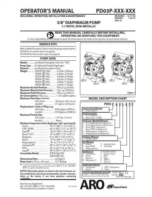
Page 2 of 12PD03P-XXX-XXX (en)EXCESSIVE AIR PRESSURES TATIC SPARK HAZARDOUS MATERIALSHAZARDOUS PRESSUREWARNING sonal injury, pump damage or property damage.Do not exceed the maximum inlet air pressure asstated on the pump model plate.Be sure material hoses and other components are ableto withstand fluid pressures developed by this pump. Check all hoses for damage or wear. Be certain dispens-ing device is clean and in proper working condition.WARNING STATIC SPARK. Can cause explosion resulting in severe injury or death. Ground pump and pumping system.PD03P-XDS-XXX and PD03P-XES-XXX Groundable Acetal pumps: Use the pump ground lug provided. Connect to a 12 ga. (minimum) wire (kit is included) to a good earth ground source.Sparks can ignite flammable material and vapors. The pumping system and object being sprayed must begrounded when it is pumping, fl ushing, recirculating orspraying fl ammable materials such as paints, solvents,lacquers, etc. or used in a location where surroundingatmosphere is conducive to spontaneous combustion.Ground the dispensing valve or device, containers, hos-es and any object to which material is being pumped.Secure pump, connections and all contact points to avoid vibration and generation of contact or static spark.Consult local building codes and electrical codes for specifi c grounding requirements.After grounding, periodically verify continuity ofelectrical path to ground. Test with an ohmmeterfrom each component (e.g., hoses, pump, clamps, con-tainer, spray gun, etc.) to ground to insure continuity.Ohmmeter should show 0.1 ohms or less.Submerse the outlet hose end, dispensing valve ordevice in the material being dispensed if possible. (Avoid free streaming of material being dispensed.)Use hoses incorporating a static e proper ventilation.Keep infl ammables away from heat, open fl ames and sparks.Keep containers closed when not in use.WARNING Can cause severe injury. Pipe exhaust away from workarea and personnel.In the event of a diaphragm rupture, material can beforced out of the air exhaust muffl er.Pipe the exhaust to a safe remote location whenpumping hazardous or infl ammable materials.Use a grounded 3/8” minimum i.d. hose between thepump and the muffl er.WARNING HAZARDOUS PRESSURE. Can result in serious injury or property damage. Do not service or clean pump, hoses or dispensing valve while the system is pressurized.Disconnect air supply line and relieve pressure fromthe system by opening dispensing valve or device and/ or carefully and slowly loosening and removing out-let hose or piping from pump.WARNING HAZARDOUS MATERIALS. Can cause seriousinjury or property damage. Do not attempt to return a pump to the factory or service center that contains hazardous material. Safe handling practices must comply with local and national laws and safety code requirements.y y y y y y y y y y y y y y y y y Obtain Material Safety Data Sheets on all materials from the supplier for proper handling instructions.WARNING EXPLOSION HAZARD. Models containing aluminum wetted parts cannot be used with 1,1,1-trichloroethane, methylene chloride or other halogenated hydrocarbon solvents which may react and explode.Check pump motor section, fluid caps, manifolds and all wetted parts to assure compatibility before using with solvents of this type.CAUTION pump wetted parts and the substance being pumped, flushed or recirculated. Chemical compatibility may change with temperature and concentration of the chemical(s) within the substances being pumped, fl ushed or circulated. For specifi c fl uid compatibility, consult the chemical manufacturer.CAUTION on mechanical stress only. Certain chemicals will significantly reduce maximum safe operating temperature. Consult the chemical manufacturer for chemical compatibility and temperature limits. Refer to PUMP DATA on page 1 of this manual.CAUTION have been trained for safe working practices,understand it’s limitations, and wear safety goggles / equipment when required.CAUTION support of the piping system. Be certain the system components are properly supported to prevent stresson the pump parts.Suction and discharge connections should be fl exible connections (such as hose), not rigid piped, and should be compatible with the substance being pumped.CAUTION pump. Do not allow pump to operate when out of material for long periods of time.Disconnect air line from pump when system sits idle for long periods of time.CAUTION® replacement parts toassure compatible pressure rating and longest service life.RE-TORQUE ALL FASTENERS BEF OREcause fasteners to loosen. Re-torque all fasteners to insure Rupture” pn \ 93122.WARNING CAUTION y y y y OPERATING AND SAFETY PRECAUTIONSREAD, UNDERSTAND, AND FOLLOW THIS INFORMATION TO AVOID INJURY AND PROPERTY DAMAGE.PD03P-XXX-XXX (en) Page 3 of 12GENERAL DESCRIPTIONThe ARO diaphragm pump offers high volume delivery even at low air pressure and a broad range of material compatibility options available. Refer to the model and option chart. ARO pumps feature stall resistant design, modular air motor / fl uid sections.Air operated double diaphragm pumps utilize a pressure dif-ferential in the air chambers to alternately create suction and positive fl uid pressure in the fl uid chambers, ball checks insure a positive fl ow of fl uid.Pump cycling will begin as air pressure is applied and it will continue to pump and keep up with the demand. It will build and maintain line pressure and will stop cycling once maxi-mum line pressure is reached (dispensing device closed) and will resume pumping as needed.AIR AND LUBE REQUIREMENTSWARNING damage, personal injury or property damage.A filter capable of filtering out particles larger than 50 microns should be used on the air supply. There is no lu-brication required other than the “O” ring lubricant which is applied during assembly or repair.If lubricated air is present, make sure that it is compatible with the “O” rings and seals in the air motor section of the pump.y y Viton ®and Hytrel ® are registered trademarks of the DuPont ® Company Loctite ® is a registered trademark of Henkel Loctite CorporationSantoprene ® is a registered trademark of Monsanto Company, licensed to Advanced Elastomer Systems, L.P . Lubriplate ® is a registered trademark of Lubriplate Division (Fiske Brothers Refi ning Company)OPERATING INSTRUCTIONSAlways flush the pump with a solvent compatible withy MAINTENANCECertain ARO “Smart Parts” are indicated which should beavailable for fast repair and reduction of down time.Provide a clean work surface to protect sensitive internal moving parts from contamination from dirt and foreign matter during service disassembly and reassembly.Keep good records of service activity and include pump in preventive maintenance program.Service Kits are available to service two separate Dia-phragm Pump functions: 1. AIR SECTION, 2. FLUID SEC-TION. The Fluid Section is divided further to match typical active MATERIAL OPTIONS.y y y y the material being pumped if the material being pumped is subject to “setting up” when not in use for a period of time.Disconnect the air supply from the pump if it is to be in-active for a few hours.The outlet material volume is governed not only by the air supply but also by the material supply available at the inlet. The material supply tubing should not be too small or restrictive. Be sure not to use hose which might col-lapse.When the diaphragm pump is used in a forced-feed (fl ooded inlet) situation, it is recommended that a Check Valve” be installed at the air inlet.Secure the diaphragm pump legs to a suitable surface to insure against damage by vibration.y yy yTYPICAL CROSS SECTIONFigure 2Page 4 of 12PD03P-XXX-XXX (en)n 637429-XX Fluid Section service kits include: Balls (see BALL OPTION, refer to -XX in chart below), Diaphragms (See DIAPHRAGMOPTION, refer to -XX in chart below) and item 19 (listed below), plus items 144, 174 and 94276 Lubriplate® grease (page 6).NOTE: Item 19 “O” ring is not used with PD03P-XXX-0XX seat option.MATERIAL CODE[A] = Aluminum [B] = Nitrile [D] = Acetal [E] = E.P .R.[GA] = Groundable Acetal [GFN] = Glass Filled Nylon [H] = Hytrel [K] = Kynar PVDF [N] = Neoprene [P] = Polypropylene[PPG] = Glass Filled Polypropylene [Sp] = Santoprene [SS] = Stainless Steel [T] = PTFE [V] = Vitono Smart Parts” keep these items on hand in addition to the service kits for fast repair and reduction of down time.PD03P-XXX-XXX (en) Page 5 of 12Page 6 of 12 PD03P-XXX-XXX (en)pIndicates parts included in 637428 Air Section Repair Kit.MATERIAL CODE[B] = Nitrile[PPG] = Glass Filled Polypropylene [CK] = Ceramic [SS] = Stainless Steel [D] = Acetal[SY] = Syn-Seal [P] = Polypropylene[U] = PolyurethaneDIAPHRAGM PUMP SERVICEGENERAL SERVICE NOTES:Inspect and replace old parts with new parts as neces-sary. Look for deep scratches on metallic surfaces, and nicks or cuts in “O” rings.Tools needed to complete disassembly and repair:5/8” socket or wrench, 7/16” socket or wrench, 3/8” socket or wrench, 5/16” Allen wrench, T-10 Torx screwdriver, torque wrench (measuring inch pounds), “O” ring pick.y y y FLUID SECTION DISASSEMBLYRemove (61) top manifold.Remove (19) “O” rings, (21) seats and (22) balls.Remove (60) bottom manifold.Remove (19) “O” rings, (21) seats and (22) balls.Remove (15) fl uid caps.Remove (6) diaphragm nut, (7) or (7 / 8) diaphragms and (5) washer.Remove (1) connecting rod from air motor.Carefully remove remaining (6) diaphragm nut, (7) or (7 / 8)diaphragms and (5) washer from (1) connecting rod. Do not mar surface of connecting rod.1.2.3.4.5.6.7.8.FLUID SECTION REASSEMBLYReassemble in reverse order.Lubricate (1) connecting rod with Lubriplate or equiva-lent “O” ring lubricant.Install (5) washers with i.d. chamfer toward diaphragm.When replacing PTFE diaphragms, install the 96533-A Santoprene diaphragm behind the Tefl on diaphragm.y y y y AIR MOTOR SECTION SERVICEService is divided into two parts - 1. Pilot Valve, 2. MajorValve.Air Motor Section Service is continued from Fluid Section repair.y PILOT VALVE DISASSEMBLYRemove (123) screws, releasing (103) covers, (121) wash-ers, (118) actuator pins and (167) pilot piston.Remove (170) spool bushing and inspect inner bore ofbushing for damage.1.2.PILOT VALVE REASSEMBLYClean and lubricate parts not being replaced from ser-vice kit.Assemble (171) “O” rings to (170) bushing and assemblebushing into (101) center body.Lubricate and assemble (167) pilot piston assembly into(170) bushing.Assemble (173 and 174) “O” rings and (121) washers to(103) covers, then insert (118) actuator pins through as-sembly.Assemble (144) “U” cups (note the lip direction) and (103)covers to (101) center body, securing with (123) screws. NOTE: Tighten (123) screws to 4 - 6 in. lbs (0.45 - 0.68 Nm).1.2.3.4.5.MAJOR VALVE DISASSEMBLYUnthread (123) screws, releasing (129) muffl er baffl e.Unthread (134) bolts and pull (135) valve block and com-ponents from (101) center body.Remove (132) gasket, (141) valve plate and (140) valveinsert from (135) valve block.Remove (134) bolts, releasing (107 and 136) plugs and(111) spool.1.2.3.4.PD03P-XXX-XXX (en) Page 7 of 12PILOT VALVE PARTSFigure 4144169 167 174MAJOR VALVE REASSEMBLYAssemble new (139 and 138) U” cups on (111) spool -LIPS MUST FACE EACH OTHER.Assemble (137) O” rings to (136) large plug.Assemble (137 and 166) O” rings to (107) small plug.Insert (111) spool into (136) large plug, then insert (136)large plug into (135) valve block, being sure the (111) spool is rotated to accept (140) valve insert.Assemble (107) small plug into (135) valve block.1.2.3.4.5.Assemble (140) valve insert and (141) valve plate to(135) valve block. Note: Assemble (140) valve insert with dished” side toward (141) valve plate. Assemble (141) valve plate with identifi cation dot toward (132) gasket.Assemble (132 and 200) gaskets and (135) valve blockto (101) center body, securing with (134) bolts. NOTE: Tighten (134) bolts to 15 - 20 in. lbs (1.7 - 2.3 Nm).Assemble (130) gasket and (129) muffl er baffl e to (101)center body, securing with (123) screws. NOTE: Tighten (123) screws to 4 - 6 in. lbs (0.45 - 0.68 Nm).6.7.8.Page 8 of 12 PD03P-XXX-XXX (en)TROUBLE SHOOTINGProduct discharged from air exhaust.Check for diaphragm rupture.Check tightness of (6) diaphragm nut.Air Bubbles in product discharge.Check connections of suction plumbing.Check “O” rings between intake manifold and fluid caps.Check tightness of (6) diaphragm nut.Pump blows air out main exhaust when stalled on either stroke.Check “U” cups on (111) spool in major valve.Check (141) valve plate and (140) insert for wear.Check (169) U” cup on (167) pilot piston.y y y y y y y y Pump blows air out main exhaust when stalled on either stroke.Check air supply.Check for plugged outlet hose.For the pump to prime itself, it must be mounted in the vertical position so that the balls will check by gravity.Check for pump cavitation - suction pipe should be sized at least as large as the inlet thread diameter of the pump for proper fl ow if high viscosity fl uids are being pumped. Suction hose must be non-collapsible type, capable of pulling a high vacuum.Check all joints on intake manifolds and suction connec-tions. These must be airtight.Inspect the pump for solid objects lodged in the dia-phragm chamber or the seat area.y y y y y y DIMENSIONAL DATAACCESSORIES67388 WALL MOUNT BRACKET ASSEMBLY96507 Wall Mount BracketY13-3-T Washer (3) (3/16")Y14-10-S Lock Washer (3) (#10)Y154-52-S Cap Screw (3)(#10 - 24 x 1/2")Figure 6PD03P-XXX-XXX (en) Page 9 of 12Page 10 of 12 PD03P-XXX-XXX (en)PD03P-XXX-XXX (en) Page 11 of 12PN 97999-1180 Page 12 of 12 PD03P-XXX-XXX (en)。
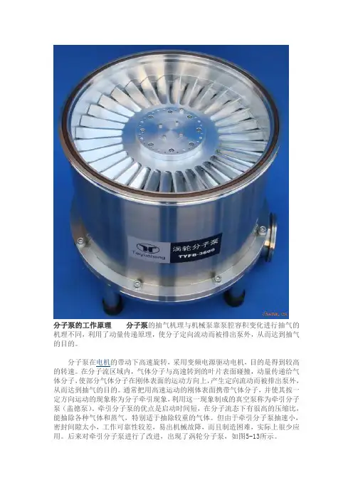
分子泵的工作原理分子泵的抽气机理与机械泵靠泵腔容积变化进行抽气的机理不同,利用了动量传递原理,使分子定向流动而被排出泵外,从而达到抽气的目的。
分子泵在电机的带动下高速旋转,采用变频电源驱动电机,目的是得到较高的转速。
在分子流区域内,气体分子与高速转到的叶片表面碰撞,动量传递给气体分子,使部分气体分子在刚体表面的运动方向上,产生定向流动而被排出泵外,从而达到抽气的目的。
通常把用高速运动的刚体表面携带气体分子,并使其按一定方向运动的现象称为分子牵引现象,利用这一现象制成的真空泵称为牵引分子泵(盖德泵)。
牵引分子泵的优点是启动时间短,在分子流态下有很高的压缩比,能抽除各种气体和蒸气,特别适于抽除较重的气体。
但由于牵引分子泵抽速小,密封间隙太小,工作可靠性较差,易出机械故降,而且制造困难,实际上很少应用。
后来对牵引分子泵进行了改进,出现了涡轮分子泵,如图5-13所示。
涡轮分子泵内有多组相间动轮叶和定轮叶,每一个轮叶上有许多按一定角度斜置的叶片,如图5-14所示。
实际的涡轮分子泵都是由多级叶列串联组成,即按动片、定片、动片等依次交替排列,见图5-13。
动叶片转动时又类似于电风扇叶片的作用,能将气体从一侧抽到另一侧。
提高分子泵的转速,有利于提高分子泵的抽速。
由于叶片转速限制,如果气体分子运动速度较大,泵抽真空就比较困难。
可以看出,涡轮分子泵也是一种机械式真空泵,通过高速旋转的多级涡轮转子叶片和静止叶片的组合进行抽气的,在分子流区域内对被抽气体产生很高的压缩比,从而获得所需要的真空性能。
涡轮分子泵极限真空比扩散泵高,可达10-8pa。
正常工作时需要一定的前级真空度,其真空度高低视泵不同略有差异,一般在1-200pa之间,可采用机械泵作为前级泵,图5-15a就是由分子泵和机械泵组成的高真空机组。
由于涡轮分子泵的转速高,通常用中频电机带动,中频电源的频率在300-400HZ之间。
涡轮分子泵一般采用水冷方式。
复合式分子泵是涡轮分子泵与牵引分子泵的串联组合,如图5-15b所示,集两种泵的优点于一体,能在很宽的压力范围10-6-1pa内,具有较大的抽速和较高的压缩比,大大提高了泵的出口压力。
分子泵起源•分子真空泵是在1911 年由德国人盖德(w · Gaede) 首先发明的,这种分子泵是在分子流区域内靠高速运动的刚体表面传递给气体分子以动量,使气体分子在刚体表面的运动方向上产生定向流动,从而达到抽气的目的。
通常把用高速运动的刚体表面携带气体分子,并使其按一定方向运动的现象称为分子牵引现象。
因此,人们将盖德发明的分子泵称为牵引分子泵。
牵引分子泵的优点是起动时间短,在分子流态下有很高的压缩比,能抽除各种气体和蒸汽,特别适于抽除较重的气体。
但同于它自身的弱点:抽速小,密封间隙太小,工作可靠性较差,易出机械故障等,因此除特殊需要外,实际上很少应用。
分子泵抽气原理•分子泵输送气体应满足二个必要条件:1). 分子泵必须在分子流状态下工作。
•因为当将一定容积的容器中所含气体的压力降低时,其中气体分子的平均自由程则随之增加。
在常压下空气分子的平均自由程只有0.06 μm ,即平均看一个气体分子只要在空间运动0.06 μm ,就可能与第二个气体分子相碰。
而在1.3Pa 时,分子间平均自由程可达4.4mm 。
在分子流范围内,气体分子的平均自由程长度远大于分子泵叶片之间的间距。
当器壁由不动的定子叶片与运动着的转子叶片组成时,气体分子就会较多地射向转子和定子叶片,为形成气体分子的定向运动打下基础。
•2). 分子泵的转子叶片必须具有与气体分子速度相近的线速度。
具有这样的高速度才能使气体分子与动叶片相碰撞后改变随机散射的特性而作定向运动。
分子泵的转速越高,对提高分子泵的抽速越有利。
实践表明,对不同分子量的气体分子其速度越大,泵抽除越困难。
•例:H<sub>2 在空气中含量甚徽,但由于H<sub>2 分子具有很大的运动速度( 最大速度为1557m /s) ,所以分子泵对 H<sub>2 的抽吸困难。
通过对极限真空中残余气体的分析,可发现氢气比重可达85 %,而分子量较大,而运动速度慢的油分子所占的比重几乎为零。
一、分子系的内部结构1.高真空接口 60.球型轴承2.前级真空接口 61.半径方向防震垫圈3.冷却水连接 63.轴向防震垫圈4.排气接口 64.电视单元5.电气连接 65.0-圈6.橡胶底座 72.0-圈10.转子73.0-圈10 a.转子中心毂 80.锁紧著14.安装螺帽 81.0-圈16.USIT接头 82.润滑油包58.螺丝 83.0-圈59螺帽 84.油包安装环二、分子泵的清洗:一般来讲,如果说前级泵没有问题,而真空在规定的时间内没有达到规定的真空值或者有漏气(排除其它的漏气)、或着解吸附作用降低,说明真空泵有点脏了,需要进行清洗,这时不用进行拆卸就可以直接进行清洗,如果太脏的话,就必须进行拆卸清理了。
直接清洗的方法如下:1.关掉分子泵,进行排气。
2.从机器上拆下分子泵,注意不要碰到接口的边缘部分。
3.拆掉冷却器、加热器(如果有的话)等4.拆掉润滑的油包5.将分子泵的高真空接口朝下垂直地放入一个适合的容器中。
6.往容器中用人无水酒精,高度以前级真空接口略低为宜,如下图。
7.上下活动分子泵几次,便于分子泵的定子和转子的叶片清洗,在无水酒精中浸泡大概5~10分钟。
8.换掉无水酒精,加入新的无水酒精,重复前面的工作,最少要重复一次。
9.拿出分子泵。
10.将高真空接口朝上,从垂直慢慢放倒到180度,以便排除磁性轴承中的酒精。
11.用一个网格放在高真空接口上,然后朝下放置,利用一个泵抽大概30分钟左右。
注意接口的密封表面不要损坏。
12.接上前级真空泵,不要开分子泵,利用前级泵抽真空,达到大概10E-1左右,以便完全清除分子泵中残留的无水酒精。
13.更换真空泵中的真空油,接上分子泵开始工作。
注意第一次抽真空时是比较慢,这是因为分子泵中有残留的酒精,属于正常情况,不必忧虑。
三、驱动马达的检查驱动马达的检查可以用两种方法,一个是带带驱动单元TCP时用示波器看波形。
一个是不带驱动器检查线路。
带驱动单元TCP的方法操作,这里要注意一点,就是探针式的霍尔传感器是没有0电位的,所以在用示波器的时候将0V线拔掉。