日本山武(azbil)光电开关HP7系列产品的技术资料
- 格式:ppt
- 大小:2.55 MB
- 文档页数:1
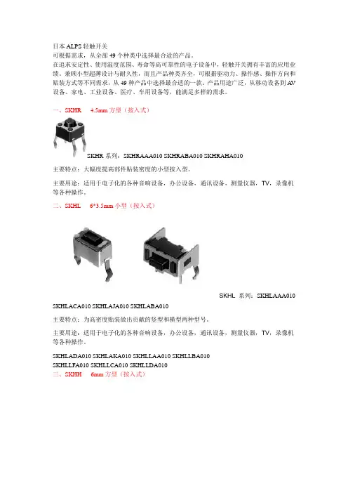
日本ALPS轻触开关可根据需求,从全部49个种类中选择最合适的产品。
在追求安定性、使用温度范围、寿命等高可靠性的电子设备中,轻触开关拥有丰富的应用业绩。
兼顾小型超薄设计与耐久性,而且产品种类齐全,可根据驱动力、操作感、操作方向和贴装方式等不同需求,从49种产品中选择最合适的一款。
产品用途广泛,从移动设备到A V 设备、家电、工业设备、医疗、车用设备等,能满足多样的需求。
一、SKHR 4.5mm方型(按入式)SKHR系列:SKHRAAA010 SKHRABA010 SKHRAHA010主要特点:大幅度提高部件贴装密度的小型按入型。
主要用途:适用于电子化的各种音响设备,办公设备,通讯设备,测量仪器,TV,录像机等各种操作。
二、SKHL 6*3.5mm小型(按入式)SKHL系列:SKHLAAA010 SKHLACA010 SKHLAJA010 SKHLABA010主要特点:为高密度贴装做出贡献的竖型和横型两种型号。
主要用途:适用于电子化的各种音响设备,办公设备,通讯设备,测量仪器,TV,录像机等各种操作。
SKHLADA010 SKHLAKA010 SKHLLAA010 SKHLLBA010SKHLLFA010 SKHLLCA010 SKHLLDA010三、SKHH 6mm方型(按入式)SKHH系列:SKHHAJA010 SKHHALA010 SKHHAQA010 SKHHAKA010主要特点:易使用且有丰富的产品种类而受到好评的6mm方型。
主要用途:适用于电子化的各种音响设备,办公设备,通讯设备,测量仪器,TV,录像机,汽车等各种操作。
SKHHAMA010 SKHHARA010 SKHHCQA010 SKHHCRA010SKHHBV A010 SKHHBWA010 SKHHBY A010 SKHHANA010SKHHAPA010 SKHHBSA010 SKHHDTA010 SKHHDUA010SKHHDHA010 SKHHDJA010 SKHHCW A010 SKHHDAA010SKHHDGA010 SKHHPJA010 SKHHPLA010 SKHHPQA010SKHHPKA010 SKHHPMA010 SKHHPRA010 SKHHQV A010SKHHQWA010 SKHHQY A010 SKHHPNA010 SKHHPPA010SKHHQNA010 SKHHLMA010 SKHHLNA010 SKHHLPA010SKHHLQA010 SKHHLRA010 SKHHLSA010 SKHHLUA010SKHHLVA010 SKHHLWA010 SKHHNHA010 SKHHNJA010 SKHHNKA010四、SKHW 6mm方型防尘型(按入式)SKHW系列:SKHWALA010 SKHWARA010 SKHWAPA010 SKHWAQA010主要特点:独有的防尘结构和敏感的操作感,适应于电子机器。
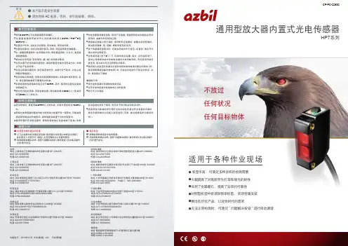
No. CP-SP-1230C光電開關HPX-AG系列使用説明書設定・操作篇常用的設定 P2 型號構成與功能對應表 P4 各部的名稱及作用 P5可設定功能一覧 P6輸出切換 P8傳感器類型 P10調諧 P12功能選擇菜單 P27定時器功能 P28心搏輸出 P29控制輸出鎖定 P30顯示功能 P32特殊功能 P35其他功能 P41與輸入輸出電路的連接 P43設 置 P50外形圖 P52規 格 P54注意事項 P55● 手動調諧可直接變更設定値。
設定値增加。
● 2點調諧①無工件狀態下按[AUTO/OK]按鈕。
②有工件狀態下按[AUTO/OK]按鈕。
③出現下記顯示,表示調諧結束。
※有關其他調諧方法,請參閱P12~26。
2● 入光時ON(LO)與遮光時ON(DO)的切換按住[FUNC/CANCEL]按鈕3s以上。
[+]按鈕切換成LO、[-]按鈕切換成DO。
● 調諧不順利的場合有工件時與無工件時的最大顯示値(9999或5000等)被顯示的場合 →請在変更傳感器類型的基礎上再次調整。
傳感器類型的変更請參閱P10。
自動調諧後有錯誤顯示的場合→根據P19的錯誤代碼采取相應對策後,再次進行調諧。
常用的設定 3(注)上述表格中“輸出形式及連接形式”和“可選項”有不能組合的情况。
詳細情况請向銷售商或本公司銷售人員咨詢。
4AUTO/OK按鈕顯示器(紅) 顯示現在的受光量。
顯示器(緑) 顯示現在的設定値(閾值)。
輸出顯示燈 輸出ON時燈亮。
輸出允許顯示燈 根據外部同期信號的狀態,控制輸出有效時燈亮。
警報輸出顯示燈警報輸出ON時燈亮。
調諧錯誤輸出顯示燈遠程調諧發生調諧錯誤時燈亮。
[AUTO/OK]按鈕 自動調諧的場合或對各項目的選擇時使用。
[+]/[-]按鈕直接変更設定値的場合或各選擇項目的移動時使用。
[FUNC/CANCEL]按鈕 向功能選擇菜單切換時或取消操作時使用。
滑動開關通道顯示切換(AG06)及設定値1/設定値2切換(AG07)時使用。
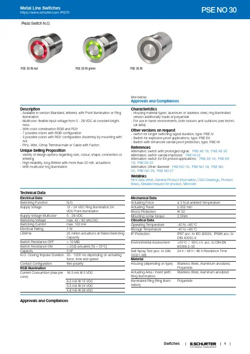
1Piezo Switch N.O.PSE 30 RI redPSE 30 RI green PSE 30 RISee below:Approvals and Compliances Description- Available in version Standard, lettered, with Point Illumination or Ring Illumination- Multicolor: flexible input voltage from 5 - 28 VDC at constant bright-ness- With color combination RGB and RGY - 7 possible colors with RGB configuration- 3 possible colors with RGY configuration Assembly by mounting with nut- Pins, Wire, Crimp Terminal male or Cable with FastonUnique Selling Proposition- Variety of design options regarding size, colour, shape, connection or lettering- High reliability, long lifetime with more than 20 mill. actuations - With multicolor ring illuminationCharacteristics- Housing material types: aluminum or stainless steel, ring illuminated version additionally made of polyamide- For use in harsh environments, both indoors and outdoors (see techni-cal data)Other versions on request- switch for longer switching signal duration, type: PSE IV - Switch for explosion proof applications, type: PSE EX- Switch with enhanced vandal proof protection, type: PSE HIReferencesAlternative: switch with prolonged signal: PSE AE 16; PSE AE 30 Alternative: switch vandal improved: PSE HI 22Alternative: switch for EX proved applications: PSE EX 16; PSE EX 19; PSE EX 22Alternative: Other diameter PSE NO 16; PSE NO 19; PSE NO 22; PSE NO 24; PSE NO 27Weblinkshtml data sheet , General Product Information , CAD-Drawings , Product News , Detailed request for product , MicrositeT echnical DataElectrical Data Switching Function N.O.Supply Voltage12 / 24 VDC Ring Illumination 24 VDC Point IlluminationSupply Voltage Multicolor 5 - 28 VDC Switching Voltage max. 42 / 60 VAC/DC Switching Current max. 100 mA Electrical Rating 1 W Lifetime 20 million actuations at Rated SwitchingCapacitySwitch Resistance OFF > 10 M ΩSwitch Resistance ON < 20 Ω actuated (Ta = 25°C)Capacity 5 nFN.O. Closing Impulse Duration 20- 1000 ms depending on actuatingforce, time and speedContact Configuration free polarity RGB IlluminationCurrent Consumtion (max per color)16.5 mA @ 5 VDC 8.2 mA @ 12 VDC 5.5 mA @ 24 VDC 4.8 mA @ 28 VDCMechanical Data Actuating Force ≤ 3 N at ambient temperature Actuating Travel 0.002 mm Shock ProtectionIK 02 Mounting screw torque 2.5 NmClimatical DataOperating Temperature -40 to +85 °C Storage Temperature -40 to +85 °CIP-ProtectionIP67 acc. to IEC 60529, IP69K acc. to DIN 40050-9Environmental Assessment +55°C␣/ 93% r.h. acc. to DIN EN 60068-2-30Salt Spray Test (acc. to DIN 50021-SS)24 h / 48 h / 96 h Residence TimeMaterialHousing (depending on type)Stainless Steel, Aluminium anodized, PolyamideActuating Area / Insert (with Ring Illumination)Stainless Steel, Aluminum anodized Illuminated Ring (Ring Illumi-nation)PolyamideApprovals and CompliancesDetailed information on product approvals, code requirements, usage instructions and detailed test conditions can be looked up in Details about ApprovalsSCHURTER products are designed for use in industrial environments. They have approvals from independent testing bodies according to national and international standards. Products with specific characteristics and requirements such as required in the automotive sector according to IATF 16949, medical technology according to ISO 13485 or in the aerospace industry can be offered exclusively with customer-specific, individual agree-ments by SCHURTER.ApprovalsApproval Reference T ype:Approval Logo Certification BodyDescriptionEUEMC: EMC directive 2004/108/EWGDGUV Test Certificate: FW 11040 Requirements for Food Processing EquipmentMIL-STD Certificate Number: 202F Method 107G, 202F Method 204D, 202F Method 213B, 416D Method RS103, 810EMethod 501.3, 810E Method 502.3, 810E Method 507.3VDE Certificate Number: DIN EN 61000-4-2, DIN EN 61000-4-4, DIN EN 61000-4-5Application standardsApplication standards where the product can be usedOrganization Design StandardDescriptionDesigned for applications acc.IEC/UL 60950IEC 60950-1 includes the basic requirements for the safety of informationtechnology equipment.CompliancesThe product complies with following Guide LinesIdentification Details InitiatorDescriptionRoHS SCHURTER AGEU Directive RoHS 2011/65/EUREACH SCHURTER AG On 1 June 2007, Regulation (EC) No 1907/2006 on the Registration,Evaluation, Authorization and Restriction of Chemicals 1 (abbreviated as"REACH") entered into force.Dimension [mm]PSE 30 RI23Design actuating area3)E)F)Legend:A = Illumination AreaB = Actuating AreaC = Width Across FlatsI = Crimp T erminal male 6.3 x 0.8 PI = Point Illumination RI = Ring IlluminationLettering:- either with/without lettering- position of the connections with respect to the position of the lettering is not definedF) with finger guidance E) without finger guidance3) elevated front design: M19 (standard, others on request)Dimension PSE M30DiagramsPSE M24 RI / PSE M27 RI / PSE M30 RI, 12/24 VA)B)C)D)A) Cable 1 (color of the LEDs), Supply voltage first LED groupB) Cable 3 (color of the LEDs), Supply voltage second LED groupC) Cable 2 (black), Common mass of both LED groupsD) Cable 4 and 5 (white), Input and output PSE switch PSE M24 RI / PSE M27 RI / PSE M30 RI, 5 VA)B)C)D)A) Cable 1 (color of the LEDs), Supply voltage first LED groupB) Cable 2 (black), Common mass of both LED groupsC) Cable 3 (color of the LEDs), Supply voltage second LED groupD) Cable 4 and 5 (white), Input and output PSE switchPSE M22 / M30 RI RGY+++−E)F)A) Cable (color of the LED), Supply voltageB) Cable (color of the LED), Supply voltageC) Cable (color of the LED), Supply voltageD) Cable (black), Common massE) Cable (white), Input and output MCS switchF) Cable (white), Input and output MCS switch Illumination options for RGYPSE M22 / M24 / M27 / M30 RI Multicolor+++−A) Cable 1 (color of the LED), Supply voltageB) Cable 2 (color of the LED), Supply voltageC) Cable 3 (color of the LED), Supply voltageD) Cable 4 (black), Common massE) Cable 5/6 (white), Input and output PSE switchF) Cable 5/6 (white), Input and output PSE switch Illumination options for RGB4074 =075 =076 =077 =All Variants56Packaging unit10 in box with insert or packed in air cushion bags- Actuating elements in ESD safe packaging- Screw nuts and sealing rings in a bag (enclosd in the box)AccessoriesDescriptionConnecting Terminal PSEConnecting TerminalPower SupplyPower Supply IP42 for LED- and Illumination applications indoor 90~264 VAC => 24 VDC 0.34 A 8 WThe specifications, descriptions and illustrations indicated in this document are based on currentinformation. All content is subject to modifications and amendments. Information furnished is believed13.2.2197。

Advanced ParametersDaily UseMaintenance & RepairExplanations for ProtectionsTroubleshooting & Warning Tones• Start-up Protection:The ESC will shut down the motor if it fails to start the motor normally within 2 seconds by increasing the throttle input. In this case, you need to move thethrottle stick back to the bottom position and restart the motor. (Possible causes of this problem: poor connection/ disconnection between the ESC and motor wires, propellers are blocked, and etc.)• Motor Lock-up Protection:The ESC will cut off its output to the motor immediately and won’t try to restart the motor when it detects the motor is locked up.In this condition, you need to pull the throttle stick to the bottom position first and then push it upward to clear the error and restart the ESC to resume the output. • Over-current Protection:The ESC will cut off its output immediately when the peak current gets close to 300A. It only restarts after you power it off and then back on. • Throttle Signal Loss Protection:When the ESC detects loss of signal for over 0.25 second, it will cut off the outputimmediately to avoid an even greater loss which may be caused by the continuous high-speed rotation of propellers. The ESC will resume the corresponding output after normal signals are received.1. How to Change the Light ColorUnscrew the two M3*8 screws for fastening the light cover with a screw driver, slide the DIP switches accordingly (as shown below) to change the light color (it’s Green by default), mount the cover back after setting.2. How to Replace a Propeller • Unscrew the two M4 *13.5 screws for fastening the blades with a screw driver and change the blade(s). If you also want to change the propeller adapter, then you need to unscrew the four M3*8 screws for fixing the adapter with another screw driver and change the whole set of propeller.• When mounting the propeller, you need to mount the bottom cover (of the propeller adapter) on the motor first, then blades, spacers and the top cover (of the propeller adapter), and then fix them with screws. Please note that the blades can rotate freely after fastening them with M4 screws, and ensure that you will also apply some glue to the screws after fastening the propeller adapter to the motor with M3 screws.Please contact Hobbywing for after-sales service timely when the power system is damaged. You can replace the damaged part(s) with the replacements (included in the product box) on condition that the coming operation won’t affect the performance of the power system, you’ve contacted and confirmed with the customer service representative; it’s forbidden to replace the damaged part(s) with other parts you configure. Please contact Hobbywing for repair timely when serious damage occurs.。

数字转速表使用说明书三和电气计器株式会社日本东京都千代田区外神田2丁目4番4号电波大楼【1】安全注意事项*本手册中使用的标志以及产品上的标志的含义如下:以下操作是为了防止人身伤害,如烧伤和触电。
在使用本仪表时,请务必遵守:功能键:最大值:最小值:数值保持单位:组合参照“5-3非接触式测量方法”和“5-4接触式测量方法”。
数值显示单位:自动关机:接触式测定模式:电池消耗警注意:在非接触式测量时,请按照下图在旋转体上粘贴反射贴(附属品)。
旋转体照射光反射贴警告旋转速度(转/分)计数(个)间隔时间(ms)旋转速度(转/秒)注意警告警告1-1 警告标志说明非常重要的使用安全指示。
·警告信息是为了防止操作人员发生意外烧伤和触电。
·注意信息是为了防止损坏仪表。
:1-2 安全使用警告1.在测量过程中,为避免衣服,头发等被卷入旋转体, 请戴工作帽穿工作服并佩戴保护眼镜。
2.在测量过程中,请绝对不要用手去触摸旋转体。
3.被测量的旋转体有异常时,请勿使用本表。
4.旋转体对测量者有可能造成危险的部分请设计挡板等 保护措施,确保安全的测量环境。
5.除了更换电池以外,切勿尝试对仪表进行修理或改造。
6.请务必执行测量前检查和每年一次的点检。
注意1.使用本仪表时,请勿从高处摔落。
2.本仪表的检测窗口不要受到强烈的撞击。
3.请勿拆开本仪表的外壳,触摸内部电路板和器件, 或对其加工改造。
使用前,请阅读以下安全防范措施。
本说明书介绍如何使用您的数字转速表SE300。
请仔细地阅读本手册。
阅读后,请将手册与产品放在一起保管,以方便随时参考。
必须遵守 警告和 注意下的操作指示,以防止发生意外烧伤或触电。
接触式适配器固定螺丝孔三脚架用螺丝孔电池盖电源键发光/检测窗转动测量提示LED 表示部【2】用途与特长2-1 用途本表是测量马达等旋转体的转动圈数的非接触式手持转速计。
使用另售适配器 ENC-3接触式测量探头,可以作为接触式转速计使用。
azbil 700系列智能阀门定位器的工作原理和应用李宝华摘要:azbil Corporation/阿自倍尔株式会社将“以人为中心的自动化”理念作为公司技术发展原动力,开展从基础技术到高端技术的多方面研发,针对控制阀智能化并实施信息化整合进入数字化工厂的市场和用户需求,在原有SVP3000 Alphaplus系列智能阀门定位器技术和应用基础上加以提升,推出了SVP7000 Alphaplus系列,可执行自动设置调整功能、搭载4个压力传感器、增强控制阀诊断功能、设置本机操作接口、增加支持FF现场总线,获得功能强化和高可靠性及高可用性;随后又有了ESD应用的号型系列。
本文试对azbil 700系列智能阀门定位器的A VP701/702型的工作原理和应用进行探析。
关键词:azbil;智能阀门定位器;700系列;A VP701/702型;工作原理;应用。
引言azbil Corporation/阿自倍尔株式会社是全球重要的自动化产品制造商,始于1906年,上世纪五十年代至九十年代为YAMATAKE-Honeywell/山武-霍尼韦尔,1998年改为YAMATAKE/山武株式会社,2006年引入azbil理念和2012年进行公司更名。
azbil将“以人为中心的自动化”理念作为公司技术发展原动力,开展从基础技术到高端技术的多方面研发,其中,针对控制阀智能化并实施信息化整合进入数字化工厂的市场和用户需求,在原有SVP3000 Alphaplus系列智能阀门定位器的技术基础及其50万台发货量的应用经验之上加以提升,2012年发布了SVP7000 Alphaplus系列,于2014年3月向市场正式推出,新系列的智能阀门定位器可执行自动设置调整功能、搭载了4个压力传感器、机内设置紧凑型双作用气动放大器,增强了控制阀诊断功能、设置了本机操作接口LUI(四个操作按键和LCD显示器)、增加支持FF现场总线、可通过EDDL和DTM以及PLUG-IN Valstaff进行系统整合,获得功能强化和高可靠性及高可用性;2016年应用于安全仪表系统SIS的ESD700系列号型符合IEC61508要求取得了SIL2/SIL3认证。