十分钟学懂战略地图
- 格式:ppt
- 大小:631.50 KB
- 文档页数:151
OM-USB-1208FS, OM-USB-1408FSU L ow Cost, MultifunctionUSB Devices with 4 Differential or 8 Single-Ended Analog Inputs U P rovides 12-Bit (OM-USB-1208FS) or 14-Bit (OM-USB-1408FS) Analog Input Resolution U M aximum Sampling Rates Ranging from 1.2 kS/s to 50 kS/s U 2 Analog Outputs U 16 Digital I/O Lines U O ne 32-Bit Counter Input Channel U N o External Power RequiredThe OM-USB-1208FS and OM-USB-1408FS dataacquisition modules offer four differential (DIFF) or eight single-ended (SE) analog inputs, two analog outputs, 16 digital I/O channels, and one counter input.These modules are USB 2.0 full speed voltage input data acquisition modules (fully compatible with both USB 1.1 and USB 2.0 ports). These are plug-and-play modules which draw power from the USB cable - no external power supply is required. All configurable options (including individual channel ranges) are software programmable, and the modules are fully software calibrated.Both modules feature eight analog voltage input channels that are processed through a single A/D converter. The analog inputs to the OM-USB-1208FS are software configurable for either eight 11-bit single-ended or four 12-bit differential inputs. The analog inputs to the OM-USB-1408FS are software configurable for either eight 13-bit single-ended or four 14-bit differential inputs.These modules have one 32-bit counter channel. The digital I/O channels are software programmable for input or output. Both models have two 12-bit analog outputs. The packaging for the OM-USB-1208FS and OM-USB-1408FS ensures ease of use in a variety of applications.OM-USB-1208FS shown actual size.The OM-USB-1208FS and OM-USB-1408FS data acquisition modules are supplied with TracerDAQsoftware which is a collection of four virtual instrument applications used to graphically display and store input data and generate output signals:• S trip Chart—Log and graph values acquire from analog inputs, digital inputs, temperature inputs and counter inputs• O scilloscope—Display values acquired fromanalog inputs• F unction Generator—Generate waveforms for analog outputs•R ate Generator—Generate waveforms for counter outputsT racerDAQ PRO is an enhanced version of TracerDAQ. A comparison of some of the features included in TracerDAQ vs TracerDAQ PRO is shown on the next page.TracerDAQ Pro Strip Chartwith Measurements.TracerDAQ Strip Chart.digital input, event counter digital input, event counter Time-of-Day Triggering No YesMath Channel No YesFeatures ComparisonSOFTWAREOM-USB-1208FS and OM-USB-1408FS modules ship with an impressive array of software, including the new TracerDAQ®, a full-featured, out-of-the-box data logging, viewing, and analysis application. Driver support and detailed example programs are included for Universal Library programming libraries for Microsoft® Visual Studio® programming languages, and other languages, including DASYLab®, and ULx for NI LabVIEW®(comprehensive library of Vls and example programs compatible with 32-bit and 64-bit LabVIEW v8.5 through 2013) and InstaCal™ installation, calibration andtest utility - powerful solutions for programmers and nonprogrammers alike. These modules operate under Microsoft Windows® XP (32-bit only) and VIST A/7/8 (32-bit and 64-bit) operating systems.ANALOG INPUTOM-USB 1208FS: These devices provide eight, 11-bit single-ended analog inputs or four, 12-bit differential analog inputs.OM-USB 1408FS: These devices provide eight, 13-bit single-ended analog inputs or four, 14-bit differential analog inputs.All devices support software selectable ranges that provide inputs from ±1V to ±20V in a differential configuration, and ±10V in a single-ended configuration.OM-USB-1408FS8 SE/4 DIFF48 kS/s max2±6.0 mA per Pin1GENERAL INFORMATIONSAMPLING RATE: When scanning continuously to computer memory (hardware-paced mode), theOM-USB-1208FS can sample at a maximum of50 kS/s, and the OM-USB-1408FS can sample ata maximum of 48 kS/s.CHANNEL-GAIN QUEUEThe channel-gain queue feature lets you configure a list of channels and gains for each scan. Each channel can have a different gain setting. The gain settings are stored in a channel-gain queue list that is written to local memory on the device.The OM-USB-1208FS and OM-USB-1408FS channel-gain queue can contain up to 16 channels listed in any order.ANALOG OUTPUTThe maximum analog output update rate for all devices depends on several factors, including USB port speed. Both devices offer two 12-bit analog outputs with a range of 0V to 4.096V.When updating continuously from computer memory (hardware-paced mode), one analog output updates at a maximum rate of 10 kS/s; two analog outputs update simultaneously at a maximum rate of 5 kS/s each. DIGITAL I/OAll devices provide 16 TTL-level digital I/O lines. Digital I/O can be programmed on each 8-bit port (Port A and Port B) for either input (default) or output.EVENT COUNTER INPUTEach device supports one 32-bit TTL-level counter that accepts inputs up to 1 MHz.SPECIFICATIONSANALOG INPUTA/D Converter Type: Successive approximation Channels: 8 single-ended (SE) or 4 differential (DIFF), software programmableInput Common-Mode Voltage Range for Linear Operation:SE Mode: CHx to GND, ±10V maxDIFF Mode: CHx to GND, -10V min, 20V max Absolute Maximum Input Voltage: CHx to GND,±28V maxInput Impedance: 122 kΩRanges: Software selectable on a per-channel basis SE Mode: ±10VD IFF Mode: ±20V, ±10V, ±5V, ±4V, ±2.5V, ±2.0V,±1.25V, ±1.0VThroughput: Maximum throughput scanning to computer memory depends on the computer being used. Software Paced: 250 S/s typ, system-dependentHardware Paced:OM-USB-1208FS: 50 kS/sOM-USB-1408FS: 48 kS/sChannel Gain Queue: Up to 16 elements, software-selectable channel and rangeResolution:OM-USB-1208FS:DIFF: 12 bits, no missing codesSE: 11 bitsOM-USB-1408FS:DIFF: 14 bits, no missing codesSE: 13 bitsCAL Accuracy (OM-USB-1208FS Only):CAL = 2.5 V, ±36.25 mV maxIntegral Linearity ErrorOM-USB-1208FS: ±1 least significant bit (LSB) typ OM-USB-1408FS: ±2 LSB typDifferential Linearity Error: ±0.5 LSB typ Repeatability: ±1 LSB typCAL Current (OM-USB-1208FS Only):Source: 5 mA maxSink: 20 μA min, 100 μA typ2.5VREF Accuracy (OM-USB 1408FS Only):±36.25 mV max2.5VREF Output Current (OM-USB 1408FS Only): Source: 5 mA maxSink: 20 μA min, 100 μA typTrigger Source (Software-Selectable):External Digital: TRIG_INClock Source: Internal; External (SYNC), rising edgetriggeredANALOG OUTPUTNumber of Channels: 2Output Range: 0V to 4.096V, 1 mV per LSB Resolution: 12 bits, 1 in 4096Throughput: Maximum throughput scanning to computer memory depends on the computer being used S oftware Paced: 250 S/s single channel typ, system-dependentHardware Paced:Single Channel: 10 kS/sDual Channel: 5 kS/s Power On and Reset VoltageOM-USB-1208FS: Initializes to 000h codeO M-USB-1408FS: 0V, ±20 mV typ, initializes to 000h codeOutput Drive (Each D/A OUT): 15 mASlew Rate: 0.8V/μs typAccuracy (All Values are ±): 0V to 4.096V: 4.0 LSB typ, 45.0 LSB maxAnalog Output Accuracy Components(All Values are ±): 0V to 4.096V% of FSR: 0.1 typ, 0.9 maxGain Error at Full Scale: 4.0 mV typ, 36.0 mV max Offset: 1.0 mV typ, 9.0 mV max% of at Full Offset Scale ±2V0.2 4 9.766 13.766Least Significant Bit- Least Significant Bit-DIGITAL I/O Digital Type: CMOSNumber of I/O: 16 (Port A0 through A7, Port B0 through B7)Configuration: 2 banks of 8Pull Up/Pull-Down Configuration: All pins pulled up to 5V through 47 kΩ resistors (default); change to pull-down using internal user-configurable jumpers.Input High Voltage: 2.0V min, 5.5V absolute max Input Low Voltage: 0.8V max, -0.5V absolute min,0V recommended minOutput High Voltage (IOH = -6.0 mA): 3.84V min Output Low Voltage (IOL = 6.0 mA): 0.33V max Power On and Reset State: InputEXTERNAL TRIGGERTrigger Source: External digital, TRIG_INTrigger Mode: Edge sensitive; software-selectable for CMOS-compatible rising or falling edgeTrigger Latency: 10 μs maxTrigger Pulse Width: 1 μs minInput Type: Schmitt trigger, 47 kΩ pull-down to ground Schmitt Trigger Hysteresis: 1.01V typ, 0.6V min, 1.5V maxInput High Voltage Threshold: 2.43V typ, 1.9V min, 3.1V maxInput High Voltage Limit: 5.5V absolute maxInput Low Voltage Threshold: 1.42V typ, 1.0V min, 2.0V maxInput Low Voltage Limit: -0.5V absolute min, 0V recommended min EXTERNAL CLOCK INPUT/OUTPUTPin Name: SYNCPin Type: BidirectionalDirection (Software-Selectable):I nput (Default): Receives A/D clock from external source; active on rising edgeO utput: Outputs internal A/D clock; active on rising edgeInput Clock Rate:OM-USB-1208FS: 50 kHz, maxOM-USB-1408FS: 48 kHz, maxClock Pulse Width:Input Mode: 1 μs minOutput Mode: 5 μs minInput Type: Schmitt trigger, 47 kΩ pull-down to ground Schmitt Trigger Hysteresis: 1.01V typ, 0.6V min, 1.5V maxInput High Voltage Threshold: 2.43V typ, 1.9V min, 3.1V maxInput High Voltage Limit: 5.5V absolute maxInput Low Voltage Threshold: 1.42V typ, 1.0V min, 2.0V maxInput Low Voltage Limit: -0.5V absolute min,0V recommended minOutput High Voltage: 4.4V min (IOH = –50 μA),3.80V min (IOH = –8 mA)Output Low Voltage: 0.1V max (IOL = 50 μA),OM-USB-1408FSshown actual size.Ordering Example: OM-USB-1208FS 12-bit voltage input USB data acquisition module (4 DE/8 SE analog input channels, 16 digital I/O, 1 counter, 2 analog outputs) and OCW-1, OMEGACARE SM extends standard 1-year warranty to a total of 2 years.Input Type: Schmitt trigger, 47 k Ω pull-down to ground Input Source: CTR screw terminal Resolution: 32 bitsMaximum Input Frequency: 1 MHz High Pulse Width: 500 ns min Low Pulse Width: 500 ns minSchmidt Trigger Hysteresis: 1.01V typ, 0.6V min, 1.5V maxInput High Voltage Threshold: 2.43V typ, 1.9V min, 3.1V maxInput High Voltage Limit: 5.5V absolute maxInput Low Voltage Threshold: 1.42V typ, 1.0V min, 2.0V maxInput Low Voltage Limit: -0.5V absolute min, 0V recommended minPOWERSupply Current: 80 mA (total current requirement; includes up to 10 mA for the status LED)+5V USB Power Available: C onnected to Self-Powered Hub: 4.5V min, 5.25V max C onnected to Bus-Powered Hub: 4.1V min, 5.25V maxOutput Current (total amount of current that can be sourced from the USB 5 V , analog outputs and digital outputs): C onnected to Self-Powered Hub or Externally Powered Root Port Hub: 420 mA maxConnected to Bus-Powered Hub: 20 mA max NON-VOLATILE MEMORY EEPROM: 1024 bytesGENERALOperating Temperature Range: 0 to 70°C (32 to 158°F), 0 to 90% RH non-condensing Storage Temperature Range: -40 to 70°C (-40 to 158°F), 0 to 90% RH non-condensing Communications: USB 2.0 Hi-speed mode (480 Mbps) is recommended; otherwise USB 1.1 full-speed mode (12 Mbps)Microcontroller Type: High performance 32-bit RISC Signal I/O Connector Type: Screw terminal USB Cable Length: 3 m (9.84') max Dimensions: 79 L x 82 W x 27 mm H (3.10 x 3.20 x 1.05") Weight: 91 g (3.2 oz)TracerDAQ Pro Strip Chartwith Measurements.TracerDAQ Strip Chart.OMEGACARE SM extended warranty program is available for models shown on this page. Ask your sales representative for full details when placing an order. OMEGACARE SM covers parts,labor and equivalent loaners.。
战略地图讲解 Revised by Hanlin on 10 January 2021战略地图-老板的思维方式和沟通路径老板的思维和员工的思维经常不在一个频道上,老板看到的是趋势,想的是未来,而员工经常看到自己的本职工作,想的是现实。
这两种思维经常没有交叉点,即便有,也很模糊。
所以有管理专家说,战略失败了,不是战略制定的不好,而是战略执行出了问题。
所谓战略执行出了问题,首先在源头上就出现了偏差,就是老板和员工的沟通出了问题,老板没有有效地把自己的思想传达给员工,导致战略是战略,执行是执行,员工做的事情和老板的战略没有关系,这样的做法,怎么可能帮助老板实现战略目标?所以,还是沟通的问题。
那么,老板该怎么和员工沟通呢?战略地图这个工具可以帮助老板实现这一点。
战略地图对于业务部门尤其适用。
通过战略地图的图解,可以很好地帮助老板分析实现盈利的路径,把老板的想法清晰地表达出来,当一个模糊的想法,被清晰地表达出来以后,员工也就更容易理解老板的想法了,这时候,模糊的战略方面描述就形成了可以理解的语言,员工理解和接受起来就更加容易了。
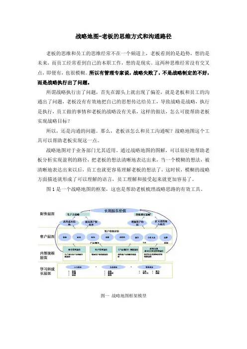
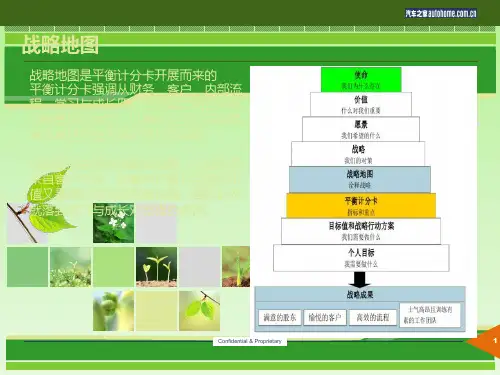
图1是一个战略地图的框架,这也是帮助老板梳理战略思路的有效工具。
图一战略地图框架模型首先我们要理解总体思考路径,先是财务层面,财务层面强调的是股东价值,就是股东怎么看待我们,通常会表现为利润增长;然后是客户层面,财务收入是谁带来的客户,客户层面强调的是如何满足客户需求,从而带来业务收入;第三个层面是内部流程层面,强调的是内部流程如何完善才能保障我们服务客户满足客户需求的能力;第四个层面是学习与成长层面,这个层面强调的无形价值,主要包括人力资本,人的能力如何提升才能保障上述三个层面的实现,信息资本,使用什么信息系统保障快捷沟通,提升沟通效率组织资本,组织氛围如何改善1、财务层面在财务层面,重点有两个方面,一个是开源,一个节流。
开源就是哪些方面可以带来业务收入,表现在地图上就是营收增长战略,这是一个战略主题,在这个主题下面又包括扩大销售收入机会和增加客户价值两个方面,所谓扩大销售收入机会是指哪些方面可以带来营业收入,结合案例,老板可以和员工清晰描述收入来源的渠道,比如说,老客户带来多少收入,新客户带来多少收入,老产品(比如杂志广告)带来多少收入,新产品(比如HR调研)带来多少收入;而在增加客户价值方面,可以描述为通过客户综合购买,比如既购买杂志,又购买调研报告,所带来的单个客户贡献,也就是增加单个客户购买量的增加,带来客户增值收入。
战略地图-老板的思维方式和沟通路径老板的思维和员工的思维经常不在一个频道上,老板看到的是趋势,想的是未来,而员工经常看到自己的本职工作,想的是现实。
这两种思维经常没有交叉点,即便有,也很模糊。
所以有管理专家说,战略失败了,不是战略制定的不好,而是战略执行出了问题。
所谓战略执行出了问题,首先在源头上就出现了偏差,就是老板和员工的沟通出了问题,老板没有有效地把自己的思想传达给员工,导致战略是战略,执行是执行,员工做的事情和老板的战略没有关系,这样的做法,怎么可能帮助老板实现战略目标?所以,还是沟通的问题。
那么,老板该怎么和员工沟通呢?战略地图这个工具可以帮助老板实现这一点。
战略地图对于业务部门尤其适用。
通过战略地图的图解,可以很好地帮助老板分析实现盈利的路径,把老板的想法清晰地表达出来,当一个模糊的想法,被清晰地表达出来以后,员工也就更容易理解老板的想法了,这时候,模糊的战略方面描述就形成了可以理解的语言,员工理解和接受起来就更加容易了。
图1是一个战略地图的框架,这也是帮助老板梳理战略思路的有效工具。
图一战略地图框架模型首先我们要理解总体思考路径,先是财务层面,财务层面强调的是股东价值,就是股东怎么看待我们,通常会表现为利润增长;然后是客户层面,财务收入是谁带来的?客户,客户层面强调的是如何满足客户需求,从而带来业务收入;第三个层面是内部流程层面,强调的是内部流程如何完善才能保障我们服务客户满足客户需求的能力;第四个层面是学习与成长层面,这个层面强调的无形价值,主要包括人力资本,人的能力如何提升才能保障上述三个层面的实现,信息资本,使用什么信息系统保障快捷沟通,提升沟通效率?组织资本,组织氛围如何改善?1、财务层面在财务层面,重点有两个方面,一个是开源,一个节流。
开源就是哪些方面可以带来业务收入,表现在地图上就是营收增长战略,这是一个战略主题,在这个主题下面又包括扩大销售收入机会和增加客户价值两个方面,所谓扩大销售收入机会是指哪些方面可以带来营业收入,结合案例,老板可以和员工清晰描述收入来源的渠道,比如说,老客户带来多少收入,新客户带来多少收入,老产品(比如杂志广告)带来多少收入,新产品(比如HR调研)带来多少收入;而在增加客户价值方面,可以描述为通过客户综合购买,比如既购买杂志,又购买调研报告,所带来的单个客户贡献,也就是增加单个客户购买量的增加,带来客户增值收入。


战略地图指南作者:专栏作家罗伯特·卡普兰发布时间:2010-5-7许多中国公司把平衡记分卡缩减为KPI考核工具,它事实上无法帮助公司建立起统一的战略行动队我在中国的大部分时间以授课为主,这比我听和学习的时间多,很不幸,这导致我没有更多的机会了解中国企业。
但是我接触的中国企业的高层管理者给我留下了非常深刻的印象,他们很容易接受新的理念,而且也有自己的想法。
中国企业特别是国有企业,多年来在生产方面希望能做到更高效率,但似乎在竞争性方面还有可以提升的地方,必须从以前行政意义上的管理风格转向更加积极专业的管理风格。
它们不像西方公司那样通过100年的发展而总结出最佳实践和做法,而是往往希望马上找到哪些是奏效的、并可以马上运用到实践中的方法。
中国的华润集团、宝钢、银联等已经在使用平衡记分卡这一工具,听说它们的效果还不错。
但随着生产的规模基础不断扩大,中国企业肯定要生产更多高附加值的产品,这样,管理者不仅需要告诉员工做什么,还要鼓励他们—如果想要取得更大的成功,就要有更多放权。
同时也需要给员工指明方向,让他们明白如何为公司带来价值。
战略说到底就是定位的问题。
未来越南、缅甸,甚至5到10年后的非洲制造成本会比中国更低,中国企业这时就要做决定,如何找到自己的独特性或者说竞争优势:我到底在哪里?怎样进行竞争?这些内容并不都是从西方搬过来的,西方也有很多理念是从日本学来的。
日本企业非常强调如何从一线员工和中层经理人那里了解想法。
我们并不仅仅希望利用员工的肌肉力量去做,更多希望挖掘出他们的知识力量。
所以,说到底战略就是一个能激发员工创新、或培育创新的结构或框架。
战略地图(Strategy map)就是这样一个工具,它从平衡记分卡演变而来,可以帮助组织向员工说明他们的战略以及有助于该战略实施的流程和系统。
战略地图还能够描画出许多内容,包括收入增长目标,有望出现利润增长的目标客户市场,能够带来更多业务和高利润的价值主张,以及所需的人力与系统投资。

如何理解与正确运用战略地图-01战略地图是企业非常重要的战略工具,平衡计分卡是企业非常重要的绩效评价工具,一般来说战略地图是平衡计分卡的先导,也是很好理解与运用平衡计分卡的基础,战略地图具有整体性,系统性和时间序列性,它对企业的平衡计分卡具有重要的指导意义。
平衡计分卡是重要的绩效评价体系,它与战略地图的相互结合使用,可谓双剑合壁,天下无敌了。
下面我们主要谈一谈如何理解与正确运用战略地图,战略地图如何与平衡计分卡结合起来使用的。
1、战略地图的概念战略地图是在平衡计分卡的基础上发展来的,与平衡计分卡相比,它增加了两个层次的东西,一是颗粒层,每一个层面下都可以分解为很多要素;二是增加了动态的层面,也就是说战略地图是动态的,可以结合战略规划过程来绘制。
2、战略地图的与平衡计分卡的关系战略地图是以平衡计分卡的四个层面目标(财务层面、客户层面、内部层面、学习与增长层面)为核心,通过分析这四个层面目标的相互关系而绘制的企业战略因果关系图。
3、战略地图的简介战略地图的核心内容包括:企业通过运用人力资本、信息资本和组织资本等无形资产(学习与成长),才能创新和建立战略优势和效率(内部流程),进而使公司把特定价值带给市场(客户),从而实现股东价值(财务)。
4、六步绘制企业战略地图第一步,确定股东价值差距(财务层面),比如说股东期望五年之后销售收入能够达到五亿元,但是公司只达到一亿元,距离股东的价值预期还差四亿元,这个预期差就是企业的总体目标;第二步,调整客户价值主张(客户层面),要弥补股东价值差距,要实现四亿元销售额的增长,对现有的客户进行分析,调整你的客户价值主张。
客户价值主张主要有四种:第一种是总成本最低,第二种价值主张强调产品创新和领导,第三种价值主张强调提供全面客户解决方案,第四种是系统锁定;第三步,确定价值提升时间表。
针对五年实现四亿元股东价值差距的目标,要确定时间表,第一年提升多少,第二年、第三年多少,将提升的时间表确定下来;第四步,确定战略主题(内部流程层面),要找关键的流程,确定企业短期、中期、长期做什么事。
企业战略地图绘制培训资料xx年xx月xx日•战略地图概述•战略地图的基本要素•战略地图的绘制步骤目录•战略地图的应用•战略地图的注意事项01战略地图概述战略地图是一种可视化的战略规划工具,将企业战略目标与财务、客户、内部业务流程、学习与成长等维度进行关联和映射,帮助企业清晰地了解战略目标及其相互之间的关系。
战略地图通过图表和指标展示企业战略目标的层次结构和关键要素,旨在使企业能够更好地实现长期战略目标。
战略地图的定义战略地图的起源与发展战略地图的起源可以追溯到20世纪90年代,当时美国管理学家罗伯特·卡普兰和戴维·诺顿提出了平衡计分卡的概念。
1996年,两位学者在《哈佛商业评论》上发表了平衡计分卡方面的第一篇论文,随后将平衡计分卡方法应用于企业战略规划和管理中,帮助企业建立战略地图。
随着时间的推移,战略地图逐渐成为企业战略规划和管理的重要工具,并在全球范围内得到广泛应用。
战略地图可以帮助企业明确战略目标,将企业战略目标与各个层次的目标进行衔接,从而确保企业战略的有效实施。
战略地图可以帮助企业进行绩效评估和管理,将战略目标与绩效指标进行关联,从而为企业提供有效的绩效评估工具。
战略地图还可以帮助企业进行战略调整和优化,根据实际情况及时调整战略目标和行动计划,使企业更加适应市场变化和竞争环境。
战略地图可以促进企业内部沟通和协调,使各部门和员工更好地理解企业战略目标和行动计划,提高企业内部合作与凝聚力。
战略地图的重要性02战略地图的基本要素目标与目的明确企业的使命、愿景和价值观,为企业发展提供导向。
根据市场需求、竞争态势等因素,制定企业中、长期发展目标。
确定各业务领域的战略目标和关键成果,为组织提供明确的发展方向。
客户与市场了解目标客户群体的需求、偏好和行为特征,为市场定位提供依据。
对市场进行细分,确定企业在目标市场中的竞争地位。
制定针对不同市场的营销策略,提升品牌知名度和客户满意度。