恒温焊台操作指导书
- 格式:doc
- 大小:73.50 KB
- 文档页数:3
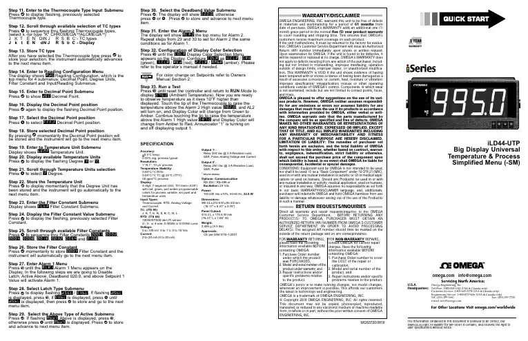
Step 11. Enter to the Thermocouple Type Input Submenu Press d to display flashing, previously selected Thermocouple type.Step 12. Scroll through available selection of TC types Press b to sequence thru flashing Thermocouple types,(select k -for type "K" CHROMEGA TM /ALOMEGA TM )J K T E N DIN J R S B C - TC types J k t E N dN J R S b C - DisplayStep 13. Store TC typeAfter you have selected the Thermocouple type press d to store your selection, the instrument automatically advances to the next menu item.Step 14. Enter to Reading Configuration MenuThe display shows RDG Reading Configuration, which is the top menu for 4 submenus: Decimal Point, Degree Units, Filter Constant and Input/Reading Submenus.Step 15. Enter to Decimal Point Submenu Press dto show DEC Decimal Point.Step 16. Display the Decimal Point positionPress d again to display the flashing Decimal Point position.Step 17. Select the Decimal Point position Press b to select FFF.F Decimal Point position.Step 18. Store selected Decimal Point positionBy pressing d momentarily the Decimal Point position will be stored and the instrument will go to the next menu item.Step 19. Enter to Temperature Unit Submenu Display shows TEMP Temperature Unit.Step 20. Display available Temperature Units Press d to display the flashing Degree °F or °C .Step 21. Scroll through Temperature Units selection Press b to select °F Degree.Step 22. Store the Temperature UnitPress d to display momentarily that the Degree Unit has been stored and the instrument will go automatically to the next menu item.Step 23. Enter the Filter Constant Submenu Display shows FLTR Filter Constant Submenu.Step 24. Display the Filter Constant Value Submenu Press d to display the flashing, previously selected Filter Constant.Step 25. Scroll through available Filter Constants Press b to sequence thru Filter Constants 0001, 0002,0004, 0008, 0016, 0032, 0064and 0128.Step 26. Store the Filter ConstantPress d momentarily to store 0004Filter Constant and the instrument will automatically go to the next menu item.Step 27. Enter Alarm 1 MenuPress a until the ALR1Alarm 1 Menu appears on the Display. In the following steps we are going to DisableLatch, Active Above, Deadband 020.0, and above Setpoint 1Value will activate Alarm 1.Step 28. Select Latch Type SubmenuPress d to display flashing DSBL / ENBL .If flashing DSBL is displayed, press a , if ENBL is displayed, press b until DSBL is displayed, then press d to store and go to the next menu item.Step 29. Select the Above Type of Active Submenu Press d . If flashing ABoV Above is displayed, press a ,otherwise press b until ABoV is displayed. Press d to store and advance to next menu item.WARRANTY/DISCLAIMEROMEGA ENGINEERING, INC. warrants this unit to be free of defects in materials and workmanship for a period of 61 months from date of purchase. OMEGA’s WARRANTY adds an additional one (1) month grace period to the normal five (5) year product warranty to cover handling and shipping time. T his ensures that OMEGA’s customers receive maximum coverage on each product.If the unit malfunctions, it must be returned to the factory for evalua-tion. OMEGA’s Customer Service Department will issue an Authorized Return (AR) number immediately upon phone or written request. Upon examination by OMEGA, if the unit is found to be defective, it will be repaired or replaced at no charge. OMEGA’s WARRANTY does not apply to defects resulting from any action of the purchaser, includ-ing but not limited to mishandling, improper interfacing, operation outside of design limits, improper repair, or unauthorized modifica-tion. This WARRANTY is VOID if the unit shows evidence of having been tampered with or shows evidence of having been damaged as a result of excessive corrosion; or current, heat, moisture or vibration; improper specification; misapplication; misuse or other operating conditions outside of OMEGA’s control. Components in which wear is not warranted, include but are not limited to contact points, fuses, and triacs.OMEGA is pleased to offer suggestions on the use of its vari-ous products. However, OMEGA neither assumes responsibil-ity for any omissions or errors nor assumes liability for any damages that result from the use if its products in accordance with information provided by OMEGA, either verbal or writ-ten. OMEGA warrants only that the parts manufactured by the company will be as specified and free of defects. OMEGA MAKES NO OTHER WARRANTIES OR REPRESENTATIONS OF ANY KIND WHATSOEVER, EXPRESSED OR IMPLIED, EXCEPT THAT OF TITLE, AND ALL IMPLIED WARRANTIES INCLUDING ANY W ARRANTY OF MERCHANTABILITY AND FITNESS FOR A PARTICULAR PURPOSE ARE HEREBY DISCLAIMED. LIMITATION OF LIABILITY: The remedies of purchaser set forth herein are exclusive, and the total liability of OMEGA with respect to this order, whether based on contract, warran-ty, negligence, indemnification, strict liability or otherwise, shall not exceed the purchase price of the component upon which liability is based. In no event shall OMEGA be liable for consequential, incidental or special damages.CONDITIONS: Equipment sold by OMEGA is not intended to be used, nor shall it be used: (1) as a “Basic Component” under 10 CFR 21 (NRC), used in or with any nuclear installation or activity; or (2) in medical appli-cations or used on humans. Should any Product(s) be used in or with any nuclear installation or activity, medical application, used on humans, or misused in any way, OMEGA assumes no responsibility as set forth in our basic WARRANT Y/DISCLAIMER language, and, additionally, purchaser will indemnify OMEGA and hold OMEGA harmless from any liability or damage whatsoever arising out of the use of the Product(s) in such a manner.RETURN REQUESTS/INQUIRIESDirect all warranty and repair requests/inquiries to the OMEGA Customer Service Department. BEFORE RE URNING ANY PRODUC (S) O OMEGA, PURCHASER MUS OB AIN AN AUTHORIZED RETURN (AR) NUMBER FROM OMEGA’S CUSTOMER SERVICE DEPART MENT (IN ORDER T O AVOID PROCESSING DELAYS). T he assigned AR number should then be marked on the outside of the return package and on any correspondence.FOR WARRANTY RETURNS, please have the followinginformation available BEFORE contacting OMEGA:1. Purchase Order number under which the product was PURCHASED,2.3. Model and serial number of the product under warranty, and Repair instructions and/or specific problems relative to the product.FOR NON-WARRANTY REPAIRS, consult OMEGA for current repair charges. Have the following information available BEFORE contacting OMEGA:1. P urchase Order number to cover the COST of the repair or calibration,2.3.Model and serial number of the product, and R epair instructions and/or specific problems relative to the product.OMEGA’s policy is to make running changes, not model changes, whenever an improvement is possible. This affords our customers the latest in technology and engineering.OMEGA is a trademark of OMEGA ENGINEERING, INC.© Copyright 2018 OMEGA ENGINEERING, INC. All rights reserved. T his document may not be copied, photocopied, reproduced, translated, or reduced to any electronic medium or machine-readable form, in whole or in part, without the prior written consent of OMEGA ENGINEERING, INC.MQS 3720/0818This Quick Start Reference provides information onsetting up your instrument for basic operation. Thelatest complete Communication and OperationalManual as well as free Software and ActiveXControls are available at or onthe CD-ROM enclosed with your shipment.The instrument is a panel mount device protected in accordance with EN 61010-1:2001, electrical safety requirements for electrical equipment for measurement, control and laboratory.Remember that the unit has no power-on switch. Building installation should include a switch or circuit-breaker that must be compliant to IEC 947-1 and 947-3. SAFETY:•Do not exceed voltage rating on the label located onthe back of the instrument housing.•Always disconnect power before changing signal andpower connections.•Do not use this instrument on a work bench withoutits case for safety reasons.•Do not operate this instrument in flammable orexplosive atmospheres.EMC:•Whenever EMC is an issue, always use shielded cables.•Never run signal and power wires in the same conduit.•Use signal wire connections with twisted-pair cables.•Install Ferrite Bead(s) on signal wire close to theinstrument if EMC problems persist.。
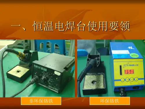
恒温电烙铁使用作业指导书
一.目的:
维护恒温电烙铁的正常使用,提供正确的方法予以指导。
二.使用者:
修理员及工程部人员
三.使用方法:
1.使用电源插头插至220V插头上,接通电源,将烙铁头放至电烙铁架上。
2.将I/O开关打开,电烙铁加热,将烙铁温度调节至相应温度。
有铅为325℃+/-25℃,无铅为370℃+/-10℃。
3.当加热指示灯HEATER亮且闪烁时,表示烙铁头温度已达到设定值左右,此时可以进行焊接动作或加锡。
4.在进行烙铁焊接时,烙铁头在焊盘上不可停留时间过长,以2-3秒为宜,以免烧坏物料与焊盘。
四:要求及注意事项
1.烙铁头在使用中须放置于烙铁架上,不可放置于其它地方。
2.烙铁使用完后,须在烙铁头上加少许焊锡,以防烙铁头氧化。
3.使用烙铁时要小心高温,以免烫伤人或其它不耐高温物品。
4.烙铁温度调节纽未经许可,其他人不可随意调节。
5.如电烙铁头不良,维修员须向领班申领、更换。
如电烙铁不能加热,交于工程部技术人员处理。
6.使用完毕,须将电烙铁电源关闭。
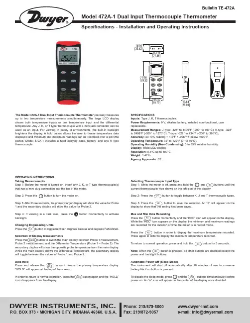
OPERATING INSTRUCTIONSTaking MeasurementsStep 1: Before the meter is turned on, insert any J, K, or T type thermocouple(s)that has a mini plug connection into the top of the meter.Step 2: Press the button to turn the meter on.Step 3: After three seconds, the primary larger display will show the value for Probe1 and the secondary display will show the value for Probe 2.Step 4: If viewing in a dark area, press the button momentarily to activatebacklight.Changing Engineering UnitsPress the button to toggle between degrees Celsius and degrees Fahrenheit.Selection of Display MeasurementsPress the button to switch the main display between Probe 1 measurement,Probe 2 measurement, and the Differential Temperature (Probe 1 – Probe 2). Thesecondary display will show the opposite probe temperature from the main display.While the main display shows the Differential Temperature, the secondary displaywill toggle between the values of Probe 1 and Probe 2.Data HoldPress and release the button to freeze the primary temperature display.“HOLD” will appear at the top of the screen.In order to return to normal operation, press the button again and the “HOLD”icon disappears from the display.The Model 472A-1 Dual Input Thermocouple Thermometer precisely measuresup to two temperature measurements simultaneously. The large LCD displayshows both temperature inputs or one temperature input and the differentialtemperature. Any J, K, or T type thermocouple with a mini-jack connector can beused as an input. For viewing in poorly lit environments, the built-in backlightbrightens the display. A hold button allows the user to freeze temperature datadisplayed and minimum and maximum readings can be recorded over a set timeperiod. Model 472A-1 includes a hard carrying case, battery, and one K typethermocouple.SPECIFICATIONSInputs: Type J, K, T thermocouples.Power Requirements: 9 V, alkaline battery, installed non-functional, userreplaceable.Measurement Ranges: J-type: -328° to 1400°F (-200° to 760°C); K-type: -328°to 2498°F (-200° to 1370°C); T-type: -328° to 734°F (-200° to 390°C);Accuracy: ±0.13%reading + 1.4°F + .006°/°F below 1000°F.Operating Temperature: 32° to 122°F (0° to 50°C).Operating Humidity (Non-Condensing): 0 to 85% relative humidity.Display:Triple LCD display.Resolution:0.1°C up to 500°C.Weight:1.47 lb.Agency Approvals: CE.[29.08][65.79]15/16RELHOLDRELHOLD°C/°FCHANNELDWYER INSTRUMENTS, INC.Phone: 219/Fax: 219/872-9057e-mail:******************©Copyright 2015 Dwyer Instruments, Inc.Printed in U.S.A. 5/15FR# 443743-00 Rev. 4BATTERY REPLACEMENTThe Dual Input Thermocouple Thermometer displays “BAT” as a visual low battery indication.To Replace the Battery:1. Make sure the unit is powered off.2. Remove thermocouples from the top of the instrument.3. Lay face down on a clean, flat surface.4. Open battery compartment by pushing in tab and lifting cover.5. Replace battery, taking note of the indicated polarity.6. Replace the cover.MAINTENANCEA periodic check of the system calibration is recommended. Model 472A-1 is not field serviceable and should be returned if repair is needed (field repair should not be attempted and may void warranty). Be sure to include a brief description of the problem plus any relevant application notes. Contact customer service to receive a return goods authorization number before shipping.If the thermometer fails to power on, it is likely that the batteries also need to be replaced.Failing to turn the thermometer off may result in malfunction of the unit. Dispose of used battery promptly and keep away fromchildren.。

Step 11. Enter to the Thermocouple Type Input Submenu Press d to display flashing, previously selected Thermocouple type.Step 12. Scroll through available selection of TC types Press b to sequence thru flashing Thermocouple types,(select k -for type "K" CHROMEGA ®/ALOMEGA ®)J K T E N DIN J R S B C - TC types J k t E N dN J R S b C - DisplayStep 13. Store TC typeAfter you have selected the Thermocouple type press d to store your selection, the instrument automatically advances to the next menu item.Step 14. Enter to Reading Configuration MenuThe display shows RDG Reading Configuration, which is the top menu for 4 submenus: Decimal Point, Degree Units,Filter Constant and Input/Reading Submenus.Step 15. Enter to Decimal Point Submenu Press d to show DEC Decimal Point.Step 16. Display the Decimal Point positionPress d again to display the flashing Decimal Point position.Step 17. Select the Decimal Point position Press b to select FFF.F Decimal Point position.Step 18. Store selected Decimal Point positionBy pressing d momentarily the Decimal Point position will be stored and the instrument will go to the next menu item.Step 19. Enter to Temperature Unit Submenu Display shows TEMP Temperature Unit.Step 20. Display available Temperature Units Press d to display the flashing Degree °F or °C .Step 21. Scroll through Temperature Units selection Press b to select °F Degree.Step 22. Store the Temperature UnitPress d to display momentarily that the Degree Unit has been stored and the instrument will go automatically to the next menu item.Step 23. Enter the Filter Constant Submenu Display shows FLTR Filter Constant Submenu.Step 24. Display the Filter Constant Value Submenu Press d to display the flashing, previously selected Filter Constant.Step 25. Scroll through available Filter Constants Press b to sequence thru Filter Constants 0001, 0002,0004, 0008, 0016, 0032, 0064and 0128.Step 26. Store the Filter ConstantPress d momentarily to store 0004Filter Constant and the instrument will automatically go to the next menu item.Step 27. Enter Alarm 1 MenuPress a until the ALR1Alarm 1 Menu appears on the Display. In the following steps we are going to DisableLatch, Active Above, Deadband 020.0, and above Setpoint 1Value will activate Alarm 1.Step 28. Select Latch Type SubmenuPress d to display flashing DSBL / ENBL .If flashing DSBL is displayed, press a , if ENBL is displayed, press buntil DSBL is displayed, then press d to store and go to the next menu item.Step 29. Select the Above Type of Active Submenu Press d . If flashing ABoV Above is displayed, press a ,otherwise press b until ABoV is displayed. Press d to store and advance to next menu item.MQS3716-SM/0305iLD24 Big Display Universal Temperature&ProcessSimplified Menu (-SM)WARRANTY/DISCLAIMEROMEGA ENGINEERING, INC. warrants this unit to be free of defects in materials and workmanship for a period of 61 months from date of purchase. OMEGA’s WARRANTY adds an additional one (1) month grace period to the normal five (5) year product warranty to cover handling and shipping time. T his ensures that OMEGA’s customers receive maximum coverage on each product.If the unit malfunctions, it must be returned to the factory for evalua-tion. OMEGA’s Customer Service Department will issue an Authorized Return (AR) number immediately upon phone or written request. Upon examination by OMEGA, if the unit is found to be defective, it will be repaired or replaced at no charge. OMEGA’s WARRANTY does not apply to defects resulting from any action of the purchaser, includ-ing but not limited to mishandling, improper interfacing, operation outside of design limits, improper repair, or unauthorized modifica-tion. This WARRANTY is VOID if the unit shows evidence of having been tampered with or shows evidence of having been damaged as a result of excessive corrosion; or current, heat, moisture or vibration; improper specification; misapplication; misuse or other operating conditions outside of OMEGA’s control. Components in which wear is not warranted, include but are not limited to contact points, fuses, and triacs.OMEGA is pleased to offer suggestions on the use of its vari-ous products. However, OMEGA neither assumes responsibil-ity for any omissions or errors nor assumes liability for any damages that result from the use if its products in accordance with information provided by OMEGA, either verbal or writ-ten. OMEGA warrants only that the parts manufactured by the company will be as specified and free of defects. OMEGA MAKES NO OTHER WARRANTIES OR REPRESENTATIONS OF ANY KIND WHATSOEVER, EXPRESSED OR IMPLIED, EXCEPT THAT OF TITLE, AND ALL IMPLIED WARRANTIES INCLUDING ANY W ARRANTY OF MERCHANTABILITY AND FITNESS FOR A PARTICULAR PURPOSE ARE HEREBY DISCLAIMED. LIMITATION OF LIABILITY: The remedies of purchaser set forth herein are exclusive, and the total liability of OMEGA with respect to this order, whether based on contract, warran-ty, negligence, indemnification, strict liability or otherwise, shall not exceed the purchase price of the component upon which liability is based. In no event shall OMEGA be liable for consequential, incidental or special damages.CONDITIONS: Equipment sold by OMEGA is not intended to be used, nor shall it be used: (1) as a “Basic Component” under 10 CFR 21 (NRC), used in or with any nuclear installation or activity; or (2) in medical appli-cations or used on humans. Should any Product(s) be used in or with any nuclear installation or activity, medical application, used on humans, or misused in any way, OMEGA assumes no responsibility as set forth in our basic WARRANT Y/DISCLAIMER language, and, additionally, purchaser will indemnify OMEGA and hold OMEGA harmless from any liability or damage whatsoever arising out of the use of the Product(s) in such a manner.RETURN REQUESTS/INQUIRIESDirect all warranty and repair requests/inquiries to the OMEGA Customer Service Department. BEFORE RE URNING ANY PRODUC (S) O OMEGA, PURCHASER MUS OB AIN AN AUTHORIZED RETURN (AR) NUMBER FROM OMEGA’S CUSTOMER SERVICE DEPART MENT (IN ORDER T O AVOID PROCESSING DELAYS). T he assigned AR number should then be marked on the outside of the return package and on any correspondence.FOR WARRANTY RETURNS, please have the followinginformation available BEFORE contacting OMEGA:1. Purchase Order number under which the product was PURCHASED,2.3. Model and serial number of the product under warranty, and Repair instructions and/or specific problems relative to the product.FOR NON-WARRANTY REPAIRS, consult OMEGA for current repair charges. Have the following information available BEFORE contacting OMEGA:1. P urchase Order number to cover the COST of the repair or calibration,2.3.Model and serial number of the product, and R epair instructions and/or specific problems relative to the product.OMEGA’s policy is to make running changes, not model changes, whenever an improvement is possible. This affords our customers the latest in technology and engineering.OMEGA is a trademark of OMEGA ENGINEERING, INC.© Copyright 2018 OMEGA ENGINEERING, INC. All rights reserved. T his document may not be copied, photocopied, reproduced, translated, or reduced to any electronic medium or machine-readable form, in whole or in part, without the prior written consent of OMEGA ENGINEERING, INC.***********************Servicing North America:Omega Engineering, Inc.Toll-Free: 1-800-826-6342 (USA & Canada only)Customer Service: 1-800-622-2378 (USA & Canada only) Engineering Service: 1-800-872-9436 (USA & Canada only) Tel: (203) 359-1660 Fax: (203) 359-7700 e-mail:**************For Other Locations Visit /worldwidehis Quick Start Reference provides information on setting up your instrument for basic operation. The latest complete Communication and Operational Manual as well as free Software and ActiveX Controls are available at or on the CD-ROM enclosed with your shipment .SAFETY CONSIDERATIONThe instrument is a panel mount device protected in accordance with EN 61010-1:2001, electrical safetyrequirements for electrical equipment for measurement, control and laboratory.Remember that the unit has no power-on switch. Building installation should include a switch or circuit-breaker that must be compliant to IEC 947-1 and 947-3.SAFETY:•Do not exceed voltage rating on the label located on the back of the instrument housing.•Always disconnect power before changing signal and power connections.•Do not use this instrument on a work bench without its case for safety reasons.•Do not operate this instrument in flammable or explosive atmospheres.EMC:•Whenever EMC is an issue, always use shielded cables. •Never run signal and power wires in the same conduit.•Use signal wire connections with twisted-pair cables.•Install Ferrite Bead(s) on signal wire close to the instrument if EMC problems persist.。
fx950焊台说明书FX950焊台是一种高性能的电子焊接工具,适用于各种电子零件的连接和修复。
本文将详细介绍FX950焊台的使用说明、注意事项以及常见问题解答等内容,以供用户参考。
一、产品概述FX950焊台是一种微处理器控制的先进电子焊接工具,具有快速加热和恒温控制的特点。
它采用陶瓷发热芯片作为加热元件,具有短时间内快速加热的优势,同时可通过控制电路精确控制焊接温度,确保焊接质量。
二、操作方法1. 连接电源:将FX950焊台的电源线插入电源插座,并接通电源开关。
焊台的数字显示屏会显示当前的温度值。
2. 设置温度:按下“设置”按钮,数字显示屏上会显示“SET”字样,此时可使用“+”和“-”按钮来设置所需的焊接温度。
设置完成后,再次按下“设置”按钮来确认设定。
3. 加热预热:在设定好的温度下,焊台将开始加热,当显示屏上的温度值达到设定温度时,焊台会自动转变为恒温模式,保持设定温度不变。
4. 开始焊接:将焊锡丝插入焊台的焊锡槽中,焊锡丝会自动融化,开始焊接。
焊接时,将焊锡丝接触到待焊接的电子零件上,等待瞬间就能焊接完成。
5. 安全停机:焊台具有定时安全功能,当焊接时间超过设定时间后,焊台会自动停机,以防止过热和意外发生。
三、注意事项1. 使用时应戴上防静电手套,并确保焊台工作区域干燥,避免电子元器件受潮。
2. 在使用前应检查焊锡槽内是否有残留的焊锡,如有,应先清理干净后再使用。
3. 注意焊接时的温度控制,避免温度过高或过低。
4. 使用时应尽量避免将焊锡丝长时间留在焊台上,以免造成焊锡丝过热。
5. 应定期检查焊台的工作状态,确保设备正常。
6. 当不使用焊台时,应断开电源并拔掉插头,以免发生意外。
四、常见问题解答1. 为什么焊台加热速度很慢?答:可能是由于供电电压不稳定或加热元件损坏导致的。
应检查供电电压是否稳定,并联系售后服务进行维修。
2. 能否更换焊台的加热元件?答:可以更换,但建议联系售后服务专业人员进行维修,以确保焊接质量和安全。
整改室焊台操作规程
1 操作前准备
1.1 用清水洗净(清洁烙铁头用的)海绵并使其保持湿润;
1.2 根据被焊工件选择合适的烙铁头;
1.3 检查调温焊台接地线和电源线应完好无损,地线连接到地桩上。
1.4电烙铁接上电源之前仔细检查导线是否完好无损,是否有电线裸露的情况,以及电烙铁焊接头是否牢固。
1.4 打开通风管道以确保焊接时空气流通。
2 操作过程
2.1 开启调温焊台电源开关;
2.2 调节恒温焊台温度,根据相关产品操作手册规定的焊接温度,调整温控按钮至适当位置,使之达到规定的温度要求;
2.3 当有特殊焊接温度要求时,应该用温度测试仪等测量设备检测烙铁头的准确温度,适当调整温控旋钮位置,使之达到要求的温度要求;
2.4 根据相关产品操作手册规定的焊接温度和焊接时间及其它要求进行焊接;
2.5 焊接完成后烙铁头用湿润海绵清洁,烙铁头头部薄烫一层锡,恒温焊台温控按钮调到最低处;
2.6 关闭电源。
3 注意事项
3.1 使用中不应磕锡和甩锡,禁止把烙铁头当撬棒使用,每次焊接中途将电烙铁放回底座时,注意烙铁头是否触碰电线以及易燃物;
3.2焊接时的松香烟雾有少量毒性,必须打开吸风开关,将风管对准
烟雾吸走。
3.3在带电设备上操作,决不能用金属笔、金属尺,或戴戒指、手表。
当手、脚或身体在汗、湿的情况下,绝不能触碰电气设备。
浙江科正电子信息产品检验有限公司。
恒温焊台注意事项恒温焊台是一种用于电子元器件焊接的工具,具有温度控制功能,可以提供稳定的焊接温度。
在使用恒温焊台时,需要注意以下几个方面:1. 温度设定:根据焊接材料的要求,正确设定焊接温度。
一般来说,焊接温度应根据焊接材料的熔点来确定,过高的温度可能会导致焊点熔化,而过低的温度则无法达到良好的焊接效果。
2. 预热时间:在使用恒温焊台进行焊接之前,需要预热一段时间,以确保焊接头达到设定的温度。
预热时间一般为几分钟,具体时间可以根据焊接材料的要求来确定。
3. 焊接时间:焊接时间应根据焊接材料的要求来确定,一般来说,焊接时间不宜过长,以免焊点过热,造成焊接材料的损坏。
4. 焊接技巧:在使用恒温焊台进行焊接时,需要掌握一定的焊接技巧。
首先,要保持焊接头和焊接材料的清洁,以免影响焊接效果。
其次,要掌握适当的焊接力度,过大的力度可能会导致焊接材料的损坏,而过小的力度则无法确保焊点的牢固性。
此外,还要注意焊接头的位置,保持焊接头与焊接材料的接触面积最大化。
5. 安全注意事项:在使用恒温焊台时,需要注意安全问题。
首先,要确保焊接台的电源线和焊接头的接地线连接良好,以防止电击事故的发生。
其次,要避免长时间连续使用焊接台,以免过热引起火灾。
此外,还要注意焊接过程中产生的烟雾和有害气体,应保持良好的通风环境,以免对身体健康造成影响。
6. 维护保养:在使用恒温焊台之后,要及时清理焊接头和焊接台,以防止焊渣和焊锡残留对焊接效果的影响。
此外,还要定期检查焊接台的温度控制系统,确保其正常工作。
总之,使用恒温焊台需要注意温度设定、预热时间、焊接时间、焊接技巧、安全注意事项和维护保养等方面。
只有正确使用和维护恒温焊台,才能确保焊接质量和工作安全。
恒温焊台操作及注意事项
一. 使用步骤:
1. 将焊台电源开关切换至ON位置;
2. 调整温度设定旋钮至200℃,待加热指示灯熄灭后,再调至工作所需温度;
3. 温度不正常时必须停止使用,并送修;
4. 清洁、擦拭烙铁头,开始使用;
二. 结束使用步骤:
1. 清洁、擦拭烙铁头并加锡保护;
2. 调整温度旋钮至最低温度;
3. 将焊台电源开关切换至OFF位置;
4. 长时间不使用时切断电源;
三.适当的工作温度:
1. 正常工作温度为旋钮调至300℃~350℃
2. 焊接面积较大或者器件较大时温度可调至400℃~480℃
四. 烙铁头的使用及保养:
1. 烙铁头使用过程中需要经常擦拭,随时锁紧烙铁确保其在合适的位置;
2. 在焊接使用过程中不可将烙铁头用力挑或挤压。
不可用摩擦的方法焊接,会损伤烙
铁头或损伤焊盘及器件;
3. 使用过程中不可敲击或者撞击烙铁手柄发热管部分,以免陶瓷发热管损坏;
4. 使用过程中不可用粗糙面摩擦烙铁头;
5. 烙铁头不可加热任何塑胶类物品;
6. 短时间不使用需将烙铁旋钮调至最低温度,长时间不使用需关闭电源;
7. 烙铁擦拭海绵需保持湿润状态;
8 使用完成后需将烙铁头擦拭干净,重新粘上新锡;
9. 如烙铁头氧化,需及时更换;
五. 注意事项:
1. 使用过程中不要磕碰,敲打烙铁手柄;
2. 不可长时间调至最高温度使用;
3.长时间不用需要给烙铁头上锡保护,然后切断电源;
4. 烙铁擦拭棉要保持湿润状态;
5. 烙铁头氧化或损坏后需及时更换;。
十一、调温焊台使用和保养规范1 目的规范调温焊台使用方法,延长设备使用寿命,保障造作人员安全。
2 适用范围适用于调温焊台的安装、使用和保养。
3 焊台的安装和使用3.1 将烙铁海绵加水后挤干(保持海绵是湿润的),并将其放在烙铁架放置海绵处。
3.2 将电线装置连接烙铁插座,将烙铁置于烙铁架底座,将插头插入电源插座;切记要接地。
3.3 将控温旋钮设在所需要温度点,依顺时针方向锁定控温旋钮。
3.4 打开电源开关接通电源,当烙铁头升至所设定的温度时,发热器指示灯即会闪亮,指示可以进行焊接作业。
4 烙铁头的使用和维护4.1 烙铁头温度选择:温度过高会减弱烙铁头功能,因此,应选择尽可能低的温度;4.2烙铁头清理:使用过程中应该常用清洁海绵清理烙铁头。
每周一次拆开烙铁头清除氧化物,防止烙铁头受损而减低温度。
4.3 清除方法:(1):设定温度为摄氏250度;(2):温度稳定后,用清洁海绵清理烙铁头,并检查烙铁头状况;(3):如果烙铁头的镀锡部分含有黑色氧化物时,可镀上新锡层,再用清洁海绵清洁烙铁头,如此反复直到氧化物除去为止,最后再镀上新锡层。
(4):若烙铁头变形或生锈严重,则直接更换新的烙铁头。
4.4 不使用时,不可让烙铁头长时间处于高温状态,会使烙铁头上的焊剂转化为氧化物,从而导致烙铁头导热功能减退。
4.5 使用完后,应在清洁的烙铁海绵上清洁好烙铁头,镀上新锡层,以防止烙铁头氧化。
5 校准烙铁头温度5.1校准条件:1.每周一上班;2.更换发热丝;3.更换烙铁头;5.2校准方法:(1):打开焊台和烙铁温度测试仪:(2):将控温旋钮设定到摄氏400度;(3):将烙铁头放至温度测试仪上稳定接触5秒后再读取实际温度;5.3使用注意事项:5.3.1 当焊台接通电源后,请勿直接接触手柄金属部分(有高温);5.3.2 切勿在焊台附近摆放易燃易爆物品,如:抹布、酒精、塑料制品等;5.3.3 烙铁清洁海绵加水时不宜过多,使用前将多余水分挤干;5.3.4 切勿使用美工刀直接剔除烙铁头上的氧化物。
QUICK205Lead Free Soldering Station大型智能无铅电焊台高周波发热极速回温操作手册感谢您购买我们的无铅电焊台,本产品是专为无铅焊接而设计的,使用前请仔细阅读本说明书,阅读后请妥为保管,以便日后查阅。
目录注意事项………………………………………………………………………部件名称………………………………………………………………………装置和使用电焊台……………………………………………………………参数……………………………………………………………………………休眠……………………………………………………………………………选择合适的烙铁头来适应焊接要求…………………………………………校准烙铁温度…………………………………………………………………烙铁头的使用…………………………………………………………………烙铁头的保养…………………………………………………………………错误标记………………………………………………………………………排除故障指南…………………………………………………………………如何检查发热器及传感器元件………………………………………………更换保险丝……………………………………………………………………规格……………………………………………………………………………烙铁头…………………………………………………………………………注意事项△!警告本使用说明书之“警告”和“注意”的定义如下:△!警告:滥用可能导致使用者死亡或重伤△!注意:滥用可能导致使用者受伤或对涉及物体造成实质破坏。
△!注意部件名称清洁海绵组装电线烙铁插座烙铁架底座装置和使用电焊台A. 烙铁架△!注意:海绵是可挤压物体,水湿则涨大。
使用海绵时,先湿水再挤干。
否则会损坏烙铁头。
2*B.连接△!注意:进行连接或拆开焊台时,切记要关掉电源,以免损坏电焊台。
1.将组装电线连接焊台插座2.将烙铁置放于烙铁架3.将插头插入电源插座。
无铅恒温电焊台WSD81标准操作作业指导书(可编辑)(可编辑优质文档)(可以直接使用,可编辑完整版资料,欢迎下载)无铅恒温电焊台WSD81 标准操作作业指导书文件编号拟制魏育婵版次审核 V1.2使用部门各使用部门设备编号无线别无批准目的规范无铅电焊台的操作步骤和操作方法,以最大程度保证设备及人员的安全生产、提高设备生产效率、保证产品生产质量。
适用范围WELLER WSD81或同类无铅恒温电焊台。
操作人员所有接受过焊接培训的人员。
设备简介简介:主要技术指标温控台:外形尺寸:166*115*101(mm)供电电压:交流220V,50/60Hz次级电压:24V额定功率:95W保险丝:T500mA,250V温控范围:50℃~450℃温度误差:±2%功能显示器:红色LED外壳防静电:表面电阻1*109Ω。
焊笔烙铁:供电电压:24V加热时间:加热到370℃大约需要25S重量(不含线):30g无铅恒温电焊台WSD81标准操作作业指导书文件编号 FSX.2A3262-001 拟制魏育婵版次审核 V1.2使用部门各使用部门设备编号无线别无批准漏电电压:2.0mV以下接地电阻:10Ω以下焊笔烙铁手柄:无防静电设计,表面电阻1*1012Ω以上电缆:1.5米,柔韧性好/防热性能好安全规则基本规则:本电焊台属贵重工具,请谨慎使用,未经培训人员不得开机、关机、操作设备。
操作人员除日常生产需要和维护外,禁止擅自拆卸、维修设备。
备件应摆放整齐,并及时清扫灰尘和垃圾,保持工位的清洁。
所有操作应遵循《FSX-SA3018防静电系统监督、点检实施细则》的要求。
使用操作安全规则:严禁使用隔离电源。
使用前应确认供电电源插座上第3脚有接入动力地线。
烙铁头附近禁止放易燃品。
将烙铁插头连接到烙铁插座时应先关掉电源。
更换烙铁头时必须关掉电源,待烙铁头冷却到室温后,方能更换。
严禁用烙铁头进行焊接以外的操作,如撬元器件。
严禁敲击烙铁头以清除焊锡。
AT8586多功能一体化集成拆焊维修系统型号:AT8586 品牌:安泰信(ATTEN)应用范围1.工业生产进行电子产品装配2.科研部门进行产品开发3.维修行业进行电子产品检修4.各企事业单位电工进行锡焊操作5.电子技术爱好者进行电子装配6.各类院校电类学生进行技能实训功能特点●传感器闭合回路,微电脑PID控制,控温精确。
LED数码显示各种状态,按键切换,方便直观。
●热风枪功率大,升温迅速,出风柔和,风量大,非常适合无铅拆焊作业。
●焊台发热体采用低压电源供电,能有效的保护敏感器件及工作人员安全。
●完美的二合一组合,采用塑料外壳,机身小巧,占用工作台面积小。
●故障自我检测报警功能。
技术参数总机额定电压:AC 220V±10% 50Hz整机功率:750W±10%(最大)工作环境:0~40℃ 相对湿度<80%储存温度:-20~80℃ 相对湿度<80%热风枪部分工作电压:AC 220V±10% 50Hz输出功率:700W±10%温度范围:100℃~500℃ 气流量120L/min(最大)温度稳定度:±2℃ (静态)设置方式:按键调节显示方式:LED数显校温方式:数字校准温度锁定方式:数字式喷咀:A1130、A1170、A1110发热丝:700W 220V AT858发热丝电焊台部分工作电压:AC 26V±10% 50Hz输出功率:50W±10%温度范围:200℃~480℃温度稳定度:±2℃ (静态)设置方式:按键调节显示方式:LED数显校温方式:数字校准温度锁定方式:数字式焊咀对地阻抗:<2Ω焊咀对地电压:<2mV烙铁头:AT-02-SI发热芯:50W四芯陶瓷发热芯包装清单(购买时请检查包装,以证实所列清单项目正确无误。
)●设备主机连热风枪手柄:1台●热风枪手柄支架:1套●电焊铁:1支●烙铁座:1个●电源线:1条●清洁海绵:1份●说明书:1本●保修卡:1份使用指南1.安装新机器第一次使用时,必须安装热风枪手柄支架,如下图。
恒温烙铁操作使用规范一、目的为了帮助员工安全、有效地使用电烙铁进行生产作业,提供正确的使用保养方法。
二、范围本公司烙铁使用人员及公司内智能恒温焊台。
三、使用方法1、使用步骤a、将电源开关调整至”ON”位置;b、插入插卡,将温度调至200℃,待温度稳定再调整至所需的工作温度;c、如温度不正常时必须停止使用,并送请维修;d、开始使用。
2、焊接五步法a、准备准备好焊锡丝和烙铁。
此时要强调的是烙铁头要保持干净,才可以沾上焊锡(俗称吃锡)b、加热元件将烙铁接触焊接点,注意首先要保持烙铁加热焊件各部分,例如印制板上引线和焊盘都使之受热,其次要注意让烙铁头的扁平部分(较大部分)接触热容量较大的部件,烙铁头的侧面或边缘部分接触热容量较小的焊件,以保持焊件均匀受热。
c、熔化焊料当焊件加热到能熔化焊料的温度后将焊锡丝置于焊点,焊料开始熔化并润湿焊点。
d、移开焊锡当熔化一定量的焊锡后移开焊锡丝。
e、移开烙铁当焊料完全润湿焊点之后移开烙铁头,注意移开烙铁头方向大致是45度角方向。
3、结束使用步骤a、清洁烙铁头并加少许锡丝保护。
b、调整温度设置到200度以下。
c、将电源开关切换至OFF位置。
d、拔下电源插头。
4、温度设置在焊接过程中如使用过低的温度将影响焊锡的流畅性。
若温度过高又会伤害线路板铜箔与焊接不完全和不美观以及过度损伤烙铁头。
1)对于贴片元件和细引脚元器件的焊点(如LED、导线),烙铁温度一般依以下标准执行:有铅温度控制在:250~350℃,无铅温度控制在:350~380℃2)对于散热较快及加锡较多的焊点(如接地焊盘、USB座),烙铁温度一般依以下标准执行:有铅温度控制在:280~380℃,无铅温度控制在:360~420℃注意事项:超过400℃温度时,勿经常或连续使用,偶尔需使用在大焊点或非常快速焊接时,尽可能短时间内使用。
四、电烙铁的使用及保养1、造成烙铁头不沾锡的原因a、温度过高,超过400度时易使沾锡面氧化。