《物理双语教学课件》Chapter 24 Diffraction 衍射理论
- 格式:doc
- 大小:337.50 KB
- 文档页数:8

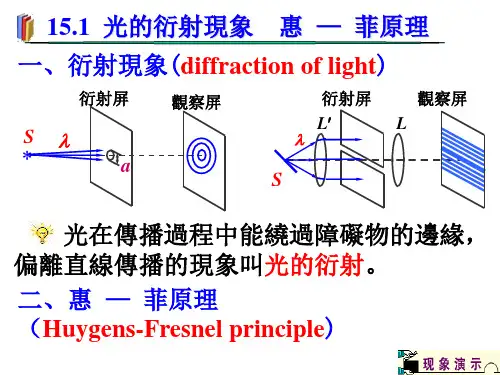

大学物理光的衍射课件CONTENTS •光的衍射现象与基本原理•典型衍射实验及其分析•衍射光栅及其应用•晶体中的X射线衍射•激光全息与光学信息处理•总结与展望光的衍射现象与基本原理01光在传播过程中遇到障碍物或小孔时,偏离直线传播的现象。
包括菲涅尔衍射和夫琅禾费衍射等。
衍射是光波遇到障碍物后产生的偏离直线传播的现象,而干涉是光波叠加产生的加强或减弱的现象。
衍射现象的定义衍射的种类衍射与干涉的区别光的衍射现象惠更斯-菲涅尔原理惠更斯原理介质中任一波面上的各点,都可以看做发射子波的波源,即可作为新波源产生球面次波,其后任意时刻这些子波的包迹面就是新的波面。
菲涅尔原理在光传播的过程中,光波前上的每一点都可以看作是新的光源,发出球面次波,这些次波在空间中相遇并相互叠加,形成新的光波前。
惠更斯-菲涅尔原理的意义解释了光的衍射现象,并为波动光学的发展奠定了基础。
03基尔霍夫衍射公式的应用用于计算各种衍射现象的振幅和相位分布,如单缝衍射、双缝干涉等。
01基尔霍夫衍射公式的表达式描述了光波在衍射屏上的振幅分布与观察屏上的振幅分布之间的关系。
02公式中各物理量的含义包括衍射屏上的复振幅分布、观察屏上的复振幅分布、光源到衍射屏的距离、衍射屏到观察屏的距离等。
基尔霍夫衍射公式典型衍射实验及其分析02单缝衍射实验装置与原理01通过单缝的衍射实验,可以观察到光波通过狭窄缝隙后的衍射现象。
实验装置包括光源、单缝、屏幕等部分。
当单色光波通过宽度与波长相当的单缝时,会在屏幕上形成明暗相间的衍射条纹。
衍射条纹特点02单缝衍射条纹呈现中间亮、两侧暗的特点。
亮条纹的间距随着衍射角的增大而减小,暗条纹则相反。
条纹间距与单缝宽度、光波长以及观察距离有关。
衍射公式与计算03根据惠更斯-菲涅尔原理,可以推导出单缝衍射的公式,用于计算衍射条纹的位置和强度分布。
双缝干涉与衍射实验装置与原理双缝干涉与衍射实验采用双缝作为分波前装置,通过两束相干光波的叠加产生干涉和衍射现象。


Chapter 24 DiffractionWhen monochromatic light from a distance source (or a laser) passes through a narrow slit and is then intercepted by a viewing screen, the light produces on the screen a diffraction pattern like that in figure.This pattern consists of abroad and intense (verybright) central maximum and a number of narrower and less intense maxima (called secondary or side maxima) to both sides. In between the maxima are minima.24.1 Diffraction by a Single Slit1.Let us consider how planewaves of light ofwavelength arediffracted by a single longnarrow slit of width a in anotherwise opaque screen B,as shown in cross section infigure (a).2.We can justify the centralbright fringe seen in figureby noting that the waves from all points in the slit travel about the same distance to reach the center of the pattern and thus are in phase there. As for the other bright fringes, we can say only that they are approximately halfway between adjacent dark fringes.3. To locate the first dark fringe at point P 1, we first mentally divide the slit into two zones of equal widths 2/a . Then we extend to P 1 a light ray r 1 from the top point of the top zoneand a light ray r 2 fromthe top point of thebottom zone . A centralaxis is drawn from thecenter of the slit toscreen C, and P 1 islocated at an angle θ tothat axis. The first darkfringe can be located at2sin 2λθ=a . It meansλθ=sin a . 4. To find the second darkfringes above and belowthe central axis, wedivide the slit into four zones of equal widths 4/a , as shown in above figure (a). We then extend rays r 1, r 2, r 3, and r 4 from the top points of the zones to point P 2, the location of the second dark fringe above the central axis. The second dark fringe can then be located at 2sin 4λθ=a or λθ2sin =a .5. The dark fringes can be located with the following general equation : ,3,2,1sin ==m for m a λθ. Above equation is derived for the case of a D >>. However, it also apply if we place a converging lens between the slit and the viewing screen andthen move the screenin so that it coincideswith the focal plane ofthe lens .6. Intensity in single-slitdiffraction : We canprove the expressionfor the intensity I ofthepattern as2)sin (ααm I I =, whereθλπαsin a =, and m I isthe greatest value ofthe intensity in thepattern. And it occurs at the central maximum (where 0=θ). Figure shows plots of the intensity of a single-slit diffraction pattern for three different slit widths .24.2 Diffraction by a Circular Aperture1. Here we consider diffractionby a circular aperture , throughwhich light can pass. Figureshows the image of a distantpoint source of light formedon photographic film placed inthe focal plane of a converginglens. (1) The image is not a point, but a circular disk surrounded by several progressively fainter secondary rings.(2) The first minimum for the diffraction pattern of a circular aperture of diameter d is given by d λθ22.1sin =.2. Resolvability : In figure (b) the angular separation of the two point sources is such that the central maximum of the diffraction patter of one source is centered on the first minimum of the diffraction pattern of the other , a condition called Rayleigh ’s criterion for resolvability . Thus two objects that are barely resolvable by this criterion must have an angular separation d R λθ22.1sin 1-=.3. When we wish to use a lens to resolve objects of small angular separation, it is desirable to make the diffraction pattern as small as possible. This can be done either by increasing the lens diameter or by using light of a shorter wavelength .24.3 Diffraction by a Double Slit1. In the double-slit experiment, we implicitly assumed that the slits were narrow compared to the wavelength of the light illuminating them; that is, λ<<a . For such narrow slits, the central maximum of the diffraction pattern of either slit covers the entire viewing screen . Moreover, the interference of light from the two slits produces bright fringes that all have approximately the same intensity .2. In practice with visible light, however, the condition λ<<a isoften not met . For relatively wide slits, the interference of light from two slits produces bright fringes that do not have the same intensity. In fact, their intensity is modified by thediffraction of the lightthrough each slit . See thefigures.3. With diffraction effects taken into account, the intensity of a double-slit interference pattern is given by22)sin )((cos ααβm I I =, in whichθλπβsin )(d = and θλπαsin )(a =.24.4 Diffraction Gratings1. One of the most usefultools in the study of lightand of objects that emit and absorb light is the diffraction grating . Somewhat like the double-slit arrangement, this device has a much greater number N of slits, often called rulings , perhaps as many as several thousand per millimeter .2. With monochromatic light incident on a diffraction grating, if we gradually increase the number of slits from two to a large number N. The maxima are now very narrow (and so called lines ). They are separated by relatively wide dark regions , as shown in above figure.3. The separation between rulings is called the grating spacing . The maxima-lines are located at ,3,2,1,0,sin ==m for m d λθ, in which the integers are then called the order numbers , and the lines are called the zeroth-order line (the central line , with m=0), the first-order line, the second-order line, and so on.4. Width of the lines: (1) we measure the half-width of the central line as the angle hw θ∆ from the center of the line at0=θ outward to where the line effectively ends and darknesseffectively begins with the first minimum. (2) The half-width of the central line is given asNd hw λθ=∆. (3) The half-width of any other line is given as θλθcos Nd hw =∆.5.An application of diffraction gratings: Figure shows a simplegrating spectroscope in which a grating is used to determine the wavelength.24.5 X-Ray Diffraction1.X rays are electromagnetic radiationwhose wavelengths are of the orderof o A1. Figure shows that x rays areproduced when electrons escapingfrom a heated filament F are accelerated by a potential difference V and strike a metal target T.2.Bragg’s law: ,3,2,1θ.dλ2=msinfor=m3.Figure shows how the interplanerspacing d can be related to the unitcell dimensiona:。