Flexiforce 传感器中文技术手册
- 格式:doc
- 大小:262.00 KB
- 文档页数:6
Flexiforce传感器分类介绍及其应用一、Flexiforce 传感器Flexiforce是一种超薄和挠性印刷电路,可很方便集成多种运用。
由于Flexiforce 像纸一样薄的结构,可弯曲和测力特性可用来测两表面之间的压力,并且能够在一些特殊环境进行测力。
Flexiforce 比其它薄膜测力产品有更好的特性、线性、磁滞、飘移、温度灵敏度。
传感的有效区域是传感器末端的直径为0.95cm的圆。
Flexiforce 由两层衬底构成。
这种衬底由聚脂纤维薄膜组成(高温传感器用的是聚酰亚胺构成)。
在每一层上运用一种导体材料(银),再加一层对压力敏感的墨水。
然后用粘合剂把两层衬底压在一起,形成了传感器。
墨水外的银边表示了对压力敏感的区域。
从敏感区域引出两个银线作为导线。
Flexiforce 传感器尾端选配一个可焊接的公的方针接头以方便连接到电路。
两边的输出线是有效的,中间的是无效的。
传感器的长度可选6cm、12cm、18cm或由客户定制。
在电路中传感器相当于一个可变电阻。
当没有负载时,传感器呈高阻状态(>5MΩ),当有负载时,电阻下载。
接一个欧姆表可以看见当在敏感区域施加外力时电阻的变化。
Flexiforce 需保存在温度-9°C74°C之间。
二、标准Flexiforce传感器标准A201传感器有下列量程供选择:Sensor A201-1 (0-1 lb)(0-4.5N)Sensor A201-25 (0-25 lb)(0-112.5N)Sensor A201-100 (0-100 lb)*(0-445N)如果要测量大于100lb的力可降低供电电压和降低反馈电阻(最小1KΩ min)可参看驱动电路图。
三、高温Flexiforce传感器高温HT201传感器有下列量程供选择:HT201-L Low: 0-30lb (133N)HT201-H High: 0-100lb (445N)四、运用Flexiforce传感器有非常多的用法。


DS Rev I 062821ISO 9001:2008 Compliant & 13485:2016 RegisteredThe FlexiForce A201 is our standard sensor and meets the requirements of most customers. The A201 is a thin and flexible piezoresistive force sensor that is available off-the-shelf in a variety of lengths for easy proof of concept. These ultra-thin sensors are ideal for non-intrusive force and pressure measurement in a variety of applications. The A201 can be used with our test & measurement, prototyping, and embedding electronics, including the FlexiForce Sensor Characterization Kit, FlexiForcePrototyping Kit, FlexiForce Quickstart Board, and the ELF™ System*. You can also use your own electronics, or multimeter.FlexiForce™Standard Model A201BenefitsPhysical PropertiesThickness 0.203 mm (0.008 in.)Length 191 mm (7.5 in.)** (optional trimmed lengths: 152 mm (6 in.), 102 mm (4 in.), 51 mm (2 in.))Width14 mm (0.55 in.)Sensing Area 9.53 mm (0.375 in.) diameterConnector3-pin Male Square Pin (center pin is inactive)Substrate Polyester Pin Spacing 2.54 mm (0.1 in.)✓ROHS COMPLIANT• Thin and flexible • E asy to use• C onvenient and affordable* Sensor will require an adapter/extender to connect to the ELF System. Contact yourTekscan representative for assistance.** Length does not include pins. Please add approximately 6 mm (0.25 in.) for pin length for a total length of approximately 197 mm (7.75 in).Typical PerformanceEvaluation ConditionsLinearity (Error)< ±3% of full scaleLine drawn from 0 to 50% loadRepeatability < ±2.5%Conditioned sensor, 80% of full force applied Hysteresis < 4.5% of full scaleConditioned sensor, 80% of full force appliedDrift< 5% per logarithmic time scaleConstant load of 111 N (25 lb)Response Time < 5µsecImpact load, output recorded on oscilloscope Operating Temperature -40°C - 60°C (-40°F - 140°F)Convection and conduction heat sources Durability≥ 3 million actuations Perpendicular load, room temperature, 22 N (5 lb)Temperature Sensitivity0.36%/°C (± 0.2%/°F)Conductive heating***All data above was collected utilizing an Op Amp Circuit (shown on the next page). If your application cannot allow an Op Amp Circuit, visit/flexiforce-integration-guides, or contact a FlexiForce Applications Engineer.***©Tekscan Inc., 2021. All rights reserved. Tekscan, the Tekscan logo, and FlexiForce are trademarks or registered trademarks of Tekscan, Inc.+1.617.464.4283|1.800.248.3669|****************|/flexiforceP urchase T oday o nline aT www .Tekscan .com /sToreVOLUMEDISCOUNTSA s k U sAb o u t Ou rSensing Area14 mm (.55 in.)191 mm (7.5 in.)6 mm (.25 in.)Actual size of sensorTrim LinesV OUT = -V REF * (R F / R S )• Polarity of V REF must be opposite the polarity of V SUPPLY • Sensor Resistance R S at no load is typically >1MΩ• Max recommended current is 2.5mAV OUTC 1R F V SS = GroundV DD = V SUPPLYC 1 = 47 pFR FEEDBACK (R F ) = 100kΩ POTENTIOMETER V REF OptionsSquare Wave Up to 5V , 50% Max Duty CycleDC0.25V - 1.25VMCP6004-V REF100K potentiometer and 47 pF are general recommendations; your specific sensor may be best suited with a different potentiometer andcapacitor. Testing should be performed to determine this.R SRecommended Circuit†This sensor can measure up to 4,448 N (1,000 lb). In order to measure higher forces, apply a lower drive voltage (-0.5 V, -0.25 V, etc.) and reduce the resistance of the feedback resistor (1kΩ min.). To measure lower forces, apply a higher drive voltage and increase the resistance of the feedback resistor.Sensor output is a function of many variables, including interface materials.Therefore, Tekscan recommends the user calibrate each sensor for the application.Standard Force Rangesas Tested with Circuit Shown4.4 N (0 - 1 lb)111 N (0 - 25 lb) 445 N (0 - 100 lb) †。
拉力传感器使用指南英文回答:Introduction:A force sensor, also known as a load cell or tension sensor, is a device used to measure the force or tension applied to it. It is widely used in various industries such as automotive, aerospace, and manufacturing. In this guide, I will provide you with the necessary information on how to use a force sensor effectively.Calibration:Before using a force sensor, it is crucial to calibrate it properly. Calibration ensures accurate and reliable measurements. To calibrate the sensor, you will need a known weight or force. Apply the known force to the sensor and record the output. Repeat this process with different known forces to create a calibration curve. This curve willallow you to convert the sensor's output to the actual force applied.Mounting:Proper mounting of the force sensor is essential for accurate measurements. Make sure the sensor is securely attached to the object or structure where the force will be applied. Avoid any external factors that may introduce additional forces or vibrations, as they can affect the sensor's readings. Additionally, ensure that the sensor is aligned with the direction of the force to obtain accurate results.Wiring and Connections:When connecting the force sensor to a data acquisition system or control unit, it is crucial to follow the manufacturer's instructions. Use the recommended cables and connectors to ensure a reliable and stable connection. Check the wiring for any loose connections or damage that may affect the sensor's performance. Proper grounding isalso important to minimize electrical noise and interference.Data Acquisition and Analysis:To measure and analyze the force data from the sensor, you will need a data acquisition system or software. Connect the sensor to the system and configure the settings according to your requirements. Start recording the force data and monitor the readings in real-time. Once the datais collected, you can analyze it using various statistical or graphical tools to gain insights into the force applied.Troubleshooting:If you encounter any issues with the force sensor, there are a few common troubleshooting steps you can take. First, check the wiring and connections to ensure they are properly secured. Next, verify that the sensor iscalibrated correctly and that the applied force fallswithin the sensor's range. If the issue persists, consult the manufacturer's documentation or contact their technicalsupport for further assistance.Conclusion:Using a force sensor requires proper calibration, mounting, wiring, and data acquisition. By following the guidelines provided in this guide, you can effectively utilize a force sensor for accurate and reliable force measurements. Remember to always refer to the manufacturer's instructions and seek professional help if needed.中文回答:引言:拉力传感器,也称为称重传感器或张力传感器,是一种用于测量施加在其上的力或张力的设备。

利用PACTWARE操作软件对VEGA物位传感器的调试说明FX60系列导向微波式物位传感器版本:3.0寇新华2006.9目录调试设备及连线------------------------------------------------------------------------------------ 3 PACTWARE的进入和初步配置---------------------------------------------------------------- 4 传感器量程的设定--------------------------------------------------------------------------------- 11 传感器的缆(棒)长------------------------------------------------------------------------------ 13 传感器测量条件的选择--------------------------------------------------------------------------- 15 电流输出的设定-------------------------------------------------------------------------------------- 17 虚假回波的处理-------------------------------------------------------------------------------------- 18 测量数据采集周期的设定-------------------------------------------------------------------------- 23 传感器的快速反应----------------------------------------------------------------------------------- 25 结束----------------------------------------------------------------------------------------------------- 27调试设备及连线调试设备:●安装了PACTWARE软件的PC;----------------------------------●VEGA的通讯接口转换器CONNECT3;----------------------连线:●可以在安装物位传感器的现场,利用专用“I2C”插头插入传感器的“I2C”插座(见下图)用安装了PACTWARE软件的PC和通讯接口转换器CONNECT3对传感器进行调试。

FlexiForce® Sensors User ManualFlexiForce® SensorsUser ManualTekscan, Inc. 307 West First Street, South Boston, MA 02127 Tel: 617.464.4500/800.248.3669 fax: 617.464.4266 Email: m arketing@ web: w Table of ContentsWELCOME (6)ISO (6)I NTRODUCTION (7)G ETTING A SSISTANCE (7)OVERVIEW (8)F LEXI F ORCE S ENSORS (8)Standard FlexiForce Sensors (8)High-Temperature FlexiForce Sensors (9)A PPLICATION (9)SENSOR LOADING CONSIDERATIONS (10)S ENSOR L OADING (10)S ATURATION (10)C ONDITIONING S ENSORS (11)CALIBRATION (12)C ALIBRATION G UIDELINES (12)SENSOR PERFORMANCE CHARACTERISTICS (13)R EPEATABILITY (13)L INEARITY (13)H YSTERESIS (13)D RIFT (13)T EMPERATURE S ENSITIVITY (13)S ENSOR L IFE /D URABILITY (14)SENSOR PROPERTIES (15)S TANDARD F LEXI F ORCE S ENSOR (M ODEL A201) (15)H IGH-T EMPERATURE F LEXI F ORCE S ENSOR (M ODEL HT201) (15)WELCOMEISOTekscan is registered to the following standard(s): •ISO 9001: 2000•ISO 13485: 2003INTRODUCTIONThis manual describes how to use Tekscan's FlexiForce Sensors. These sensors are ideal for designers, researchers, or anyone who needs to measure forces without disturbing the dynamics of their tests. The FlexiForce sensors can be used to measure both static and dynamic forces (up to 1000 lbf.), and are thin enough to enable non-intrusive measurement.The FlexiForce sensors use a resistive-based technology. The application of a force to the active sensing area of the sensor results in a change in the resistance of the sensing element in inverse proportion to the force applied.GETTING ASSISTANCETekscan, Inc. will provide technical assistance for any difficulties you may experience using your FlexiForce system.Write, call or fax us with any concerns or questions. Our knowledgeable support staff will be happy to help you. Comments and suggestions are always welcome.FlexiForcea division of Tekscan, Inc.307 West First StreetSouth Boston, MA 02127-1309Phone: (617) 464-4500Fax: (617) 464-4266E-mail: flexiforce@Copyright © 2008 by Tekscan, Incorporated. All rights reserved. No part of this publication may be reproduced, transmitted, transcribed, stored in a retrieval system, or translated into any language or computer language, in any form or by any means without the prior written permission of Tekscan, Inc., 307 West First Street, South Boston, MA 02127-1309. Tekscan, Inc. makes no representation or warranties with respect to this manual. Further, Tekscan, Inc. reserves the right to make changes in the specifications of the product described within this manual at any time without notice and without obligation to notify any person of such revision or changes.FlexiForce is a registered trademarks of Tekscan, Inc.Windows 95/98/ME/2000/XP/Vista, MS-DOS, Word, Notepad, and Excel are registered trademarks of Microsoft Corporation.OVERVIEWThis section outlines Sensor Construction and Application.FLEXIFORCE SENSORSThe FlexiForce sensor is an ultra-thin and flexible printed circuit, which can be easily integrated into most applications. With its paper-thin construction, flexibility and force measurement ability, the FlexiForce force sensor can measure force between almost any two surfaces and is durable enough to stand up to most environments. FlexiForce has better force sensing properties, linearity, hysteresis, drift, and temperature sensitivity than any other thin-film force sensors. The "active sensing area" is a 0.375” diameter circle at the end of the sensor.The sensors are constructed of two layers of substrate. This substrate is composed of polyester film (or Polyimide in the case of the High-Temperature Sensors). On each layer, a conductive material (silver) is applied, followed by a layer of pressure-sensitive ink. Adhesive is then used to laminate the two layers of substrate together to form the sensor. The silver circle on top of the pressure-sensitive ink defines the “active sensing area.” Silver extends from the sensing area to the connectors at the other end of the sensor, forming the conductive leads.FlexiForce sensors are terminated with a solderable male square pin c onnector, which allows them to be incorporated into a circuit. The two outer pins of the connector are active and the center pin is inactive. The length of the sensors can be trimmed by Tekscan to predefined lengths of 2”, 4” and 6” or can be trimmed by the customer. If the customer trims the sensor, a new connector must be attached. This can be accomplished by purchasing staked pin connectors and a crimping tool. A conductive epoxy can also be used to adhere small wires to each conductor. The sensor acts as a variable resistor in an electrical circuit. When the sensor is unloaded, its resistance is very high (greater than 5 Meg-ohm); when a force is applied to the sensor, the resistance decreases. Connecting an ohmmeter to the outer two pins of the sensor connector and applying a force to the sensing area can read the change in resistance.Sensors should be stored at temperatures in the range of 15°F (-9°C) to 165°F (74°C) Standard FlexiForce SensorsThe Standard A201 sensor is available in the following force ranges:•Sensor A201-1 (0-1 lb. force range)•Sensor A201-25 (0-25 lb. force range)•Sensor A201-100 (0-100 lb. force range)** In order to measure forces above 100 lbs. (up to 1000 lbs), apply a lower drive voltage andreduce the resistance of the feedback resistor (1kΩ min.). See the sample drive circuit below.High-Temperature FlexiForce SensorsThe High-Temperature HT201 sensor is available in the following force ranges* (as tested with the sample drive circuit).•Sensor HT201-L Low: 0-30lb (133N) force range•Sensor HT201-H High: 0-100lb (445N) force range* In order to measure forces outside specified ranges, use recommended circuit and adjustdrive voltage and/or reference resistanceAPPLICATIONThere are many ways to integrate the FlexiForce sensor into an application. One way is to incorporate it into a force-to-voltage circuit. A means of calibration must then be established to convert the output into the appropriate engineering units. Depending on the setup, an adjustment could then be done to increase or decrease the sensitivity of the sensor.An example circuit is shown below. In this case, it is driven by a -5 V DC excitation voltage. This circuit uses an inverting operational amplifier arrangement to produce an analog output based on the sensor resistance and a fixed reference resistance (R F). An analog-to-digital converter can be used to change this voltage to a digital output. In this circuit, the sensitivity of the sensor could be adjusted by changing the reference resistance (R F) and/or drive voltage (VT);a lower reference resistance and/or drive voltage will make the sensor less sensitive, and increase its active force range.In the circuit shown, the dynamic force range of the sensor can be adjusted by changing the reference resistor (R F) or by changing the Drive Voltage (V O). Refer tothe Saturation section for additional information.SENSOR LOADING CONSIDERATIONSThe following general sensor loading guidelines can be applied to most applications, and will help you achieve the most accurate results from your tests. It is important that you read the Sensor Performance Characteristics section for further information on how to get the most accurate results from your sensor readings.SENSOR LOADINGThe entire sensing area of the FlexiForce sensor is treated as a single contact point. For this reason, the applied load should be distributed evenly across the sensing area to ensure accurate and repeatable force readings. Readings may vary slightly if the load distribution changes over the sensing area.Note that the sensing area is the silver circle on the top of the sensor only.It is also important that the sensor be loaded consistently, or in the same way each time.If the footprint of the applied load is smaller than the sensing area, the load should not be placed near the edges of the sensing area, to ensure an even load distribution.It is also important to ensure that the sensing area is the entire load path, and that the load is not supported by the area outside of the sensing area.If the footprint of the applied load is larger than the sensing area, it may be necessary to use a "puck." A puck is a piece of rigid material (smaller than the sensing area) that is placed on the sensing area to ensure that the entire load path goes through this area. The puck must not touch any of the edges of the sensing area, or these edges may support some of the load and give an erroneous reading.The FlexiForce sensor reads forces that are perpendicular to the sensor plane. Applications that impart "shear"forces could reduce the life of the sensor. If the application will place a "shear" force on the sensor, it should be protected by covering it with a more resilient material.If it is necessary to mount the sensor to a surface, it is recommended that you use tape, when possible. Adhesives may also be used, but make sure that the adhesive will not degrade the substrate (polyester) material of the sensor before using it in an application. Adhesives should not be applied to the sensing area; however, if it is necessary, ensure that the adhesive is spread evenly. Otherwise, any high spots may appear as load on the sensor.SATURATIONThe Saturation force is the point at which the device output no longer varies with applied force. The saturation force of each sensor is based on the maximum recommended force specified by Tekscan, which is printed on the system packaging or the actual sensor, along with the "Sensitivity."02/05/09 FlexiForce Sensor User Manual (Rev G)The saturation value is based on using the circuit and the values shown in the example circuit in the ‘Application’ section. In this example, the saturation force (maximum force) of each sensor is related to the RF (reference resistance), and can be altered by changing the sensitivity. The sensitivity of the sensor would be adjusted by changing the reference resistance (RF); a lower reference resistance will make the system less sensitive, and increase its active force range.It is essential that the sensor(s) do not become saturated during testing.CONDITIONING SENSORSExercising, or Conditioning a sensor before calibration and testing is essential in achieving accurate results. It helps to lessen the effects of drift and hysteresis. Conditioning is required for new sensors, and for sensors that have not been used for a length of time.To condition a sensor, place 110% of the test weight on the sensor, allow the sensor to stabilize, and then remove the weight. Repeat this process four or five times. The interface between the sensor and the test subject material should be the same during conditioning as during calibration and actual testing.IMPORTANT! Sensors must be properly conditioned prior to calibration and use.CALIBRATIONCalibration is the method by which the sensor’s electrical output is related to an actual engineering unit, such as pounds or Newtons. To calibrate, apply a known force to the sensor, and equate the sensor resistance output to this force. Repeat this step with a number of known forces that approximate the load range to be used in testing. Plot Force versus Conductance (1/R). A linear interpolation can then be done between zero load and the known calibration loads, to determine the actual force range that matches the sensor output range.Resistance Curve: Conductance Curve:CALIBRATION GUIDELINESThe following guidelines should be considered when calibrating a sensor:•Apply a calibration load that approximates the load to be applied during system use, using dead weights or a testing device (such as an MTS or Instron). If you intend to use a "puck" during testing, also use it when calibrating the sensor. See Sensor LoadingConsiderations for more information on using a puck.•Avoid loading the sensor to near saturation when calibrating. If the sensor saturates at a lower load than desired, adjust the "Sensitivity."•Distribute the applied load evenly across the sensing area to ensure accurate force readings. Readings may vary slightly if the load distribution changes over the sensingarea.•Sensors should be calibrated at the same temperature for which testing will occur. This is especially important for High-Temp Sensors, as these sensors have a wide operatingtemperature range. If multiple temperatures are used during testing, calibrate the sensors at those same multiple temperatures.Note: Read the Sensor Performance Characteristics section before performing a Calibration.SENSOR PERFORMANCE CHARACTERISTICSThere are a number of characteristics of sensors, which can affect your results. This section contains a description of each of these conditions, and recommendations on how to lessen their effects.REPEATABILITYRepeatability is the ability of the sensor to respond in the same way to a repeatedly applied force. As with most measurement devices, it is customary to exercise, or "condition" a sensor before calibrating it or using it for measurement. This is done to reduce the amount of change in the sensor response due to repeated loading and unloading. A sensor is conditioned by loading it to 110% of the test weight four or five times. Follow the full procedure in the Conditioning Sensors section.LINEARITYLinearity refers to the sensor’s response (digital output) to the applied load, over the range of the sensor. This response should ideally be linear; and any non-linearity of the sensor is the amount that its output deviates from this line. A calibration is performed to "linearize" this output as much as possible. FlexiForce standard sensors are linear within +/- 3%. FlexiForce High-Temperature sensors have a linearity that is 1.2% of full scale.HYSTERESISHysteresis is the difference in the sensor output response during loading and unloading, at the same force. For static forces, and applications in which force is only increased, and not decreased, the effects of hysteresis are minimal. If an application includes load decreases, as well as increases, there may be error introduced by hysteresis that is not accounted for by calibration. DRIFTDrift is the change in sensor output when a constant force is applied over a period of time. If the sensor is kept under a constant load, the resistance of the sensor will continually decrease, and the output will gradually increase. It is important to take drift into account when calibrating the sensor, so that its effects can be minimized. The simplest way to accomplish this is to perform the sensor calibration in a time frame similar to that which will be used in the application. TEMPERATURE SENSITIVITYIn general, your results will vary if you combine high loads on the sensor with high temperatures. To ensure accuracy, calibrate the sensor at the temperature at which it will be used in the application. If the sensor is being used at different temperatures, perform a calibration at each of these temperatures, save the calibration files, then load the appropriate calibration file when using the sensor at that temperature.SENSOR LIFE / DURABILITYSensor life depends on the application in which it is used. Sensors are reusable, unless used in applications in which they are subjected to severe conditions, such as against sharp edges, or shear forces. FlexiForce sensors have been successfully tested at over one million load cycles using a 50 lb. force.Rough handling of a sensor will also shorten its useful life. For example, a sensor that is repeatedly installed in a flanged joint will have a shorter life than a sensor installed in the same joint once and used to monitor loads over a prolonged period. After each installation, visually inspect your sensors for physical damage.It is also important to keep the sensing area of the sensor clean. Any deposits on this area will create uneven loading, and will cause saturation to occur at lower applied forces.SENSOR PROPERTIESSTANDARD FLEXIFORCE SENSOR (MODEL A201)Sensor PropertiesThickness 0.008(0.208mm)Length 8” (203 mm) 6” (152 mm) 4” (102 mm) 2” (51 mm)Width 0.55” (14 mm)Sensing Area 0.375” (9.53 mm) diameterConnector 3-pin male square pin (center pin is inactive) Typical PerformanceForce Ranges 0-1 lb (4.4 N)0-25 lbs (110 N) 0-100 lbs (440 N)*Operating TemperatureRange15°F to 140°F (-9°C to 60°C)Linearity (Error) +/- 3%Repeatability +/- 2.5% of full scale (conditioned sensor, 80% force applied) Hysteresis <4.5% of full scale (conditioned sensor, 80% force applied)Drift <5% per logarithmic time scale (constant load of 90% sensor rating) Response Time <5 microsecondsOutput Change/Degree F Up to 0.2% (~0.36% / °C).Loads <10 lbs, operating temperature can be increased to 165°F (74°C).HIGH-TEMPERATURE FLEXIFORCE SENSOR (MODEL HT201) Sensor PropertiesThickness 0.008”(0.203mm) Length 7.75” (197 mm)Optional: 6” (152 mm)Trimmed: 4” (102 mm)Lengths: 2” (51 mm)Width 0.55” (14 mm)Sensing Area 0.375” (9.53 mm) diameterConnector 3-pin Male Square Pin (center pin is inactive) Substrate Polyimide (ex: Kapton)Typical PerformanceForce Ranges 0-30 lbs (133N)0-100 lbs (445N)Operating Temperature Range 15°F to 400°F (-9°C to 204°C)Repeatability +/- 3.5% of full scaleLinearity +/- 1.2% of full scaleHysteresis 3.6% of full scaleDrift 3.3% per log timeOutput Change/Degree F 0.16%。
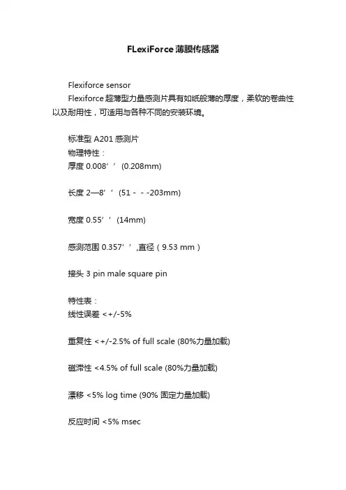
FLexiForce薄膜传感器Flexiforce sensorFlexiforce超薄型力量感测片具有如纸般薄的厚度,柔软的卷曲性以及耐用性,可适用与各种不同的安装环境。
标准型 A201感测片物理特性:厚度0.008’’(0.208mm)长度 2—8’’(51---203mm)宽度0.55’’(14mm)感测范围0.357’’,直径(9.53 mm)接头 3 pin male square pin特性表:线性误差 <+/-5%重复性 <+/-2.5% of full scale (80%力量加载)磁滞性 <4.5% of full scale (80%力量加载)漂移 <5% log time (90% 固定力量加载)反应时间 <5% msec工作温度15°F—140°F(-9°C—60°C)力量量测范围 0---1 ibs (4.4N)0---25 ibs(110N)0---100 ibs(440N)温度灵敏度0.2%/°F(0.36%/°C)公司简介麦思科技有限公司成立于2001年,公司创立宗旨是为用户提供最新的测量技术与全方位的压力分布感测技术服务。
随着科技发展及应用技术的日新月异,为因应客户对测量技术的需求与日俱增,以期能为不同的用户提供更完备的测量解决方案。
我们乐于接受不同的挑战,协助客户解决问题是我们努力的方向,我们以客户满意的评价为荣,也因客户的支持与肯定,麦思科技得以不断的茁壮成长。
公司主营代理美国T ekscan公司压力分布测量全系产品,为美国Tekscan中国区的一级代理商。
创立于1987的美国T ekscan公司已经成为世界高解析薄膜接触压力测量系统供应商的领导者。
我们的产品已应用于各种产业,从工业到医学T ekscan的高解析度薄膜压力感测技术无处不在,包括汽车、人体工学、封装、半导体以及更多的应用。

FSS SeriesLow Profile Force SensorDESCRIPTIONThe FSS Series Force Sensor provides precise, reliable force sensing performance in a compact, commercial-grade package at a cost effective price. The sensor features a proven sensing technology that uses a specialized piezoresistive,micromachined silicon sensing element. The low power,unamplified, uncompensated Wheatstone bridge circuit design provides inherently stable mV outputs over the force range.Force sensors operate on the principle that the resistance of silicon-implanted piezoresistors will increase when theresistors flex under any applied force. The sensor concentrates force from the application, through the stainless steel ball, directly to the silicon-sensing element. The amount ofresistance changes in proportion to the amount of force being applied. This change in circuit resistance results in a corresponding mV output level change.The sensor package design incorporates patented modular construction. The use of innovative elastomeric technology and engineered molded plastics results in overforce capacities of up to three times the rated force. The stainless steel ball provides excellent mechanical stability and is adaptable to a variety of applications.The FSS Series Sensor delivered 20 million operations in Mean Cycles to Failure (MCTF) reliability testing at 50°C [122°F]. This test determines the number of possible sensor operations at full scale until failure.FEATURES AND BENEFITS∙ RoHS-compliant materials meet Directive 2002/95/ECallows use in industries requiring regulation compliance ∙ Low deflection (approx. 30 µm typical at full scale) helpsreduce measurement error∙ Direct mechanical coupling of the actuation ball to thesense element reduces coupling errors and keeps mechanical hysteresis to a minimum∙ Product rating of 20 million MCTF at 25 °C [77 °F], subjectto application variation, provides for consistent output over time and reduces repairs or replacements∙ Small size minimizes space on the printed circuit board(PCB)∙ Provides enhanced sensitivity without compromisingsignal integrity, resulting in low system noise and reducing measurement errors∙ Electrically ratiometric output accommodates supplyvoltage variations, leading to low ratiometricity error ∙ Low voltage supply allows for use in many batterypowered applications∙ High resistance to electrostatic discharge (ESD) meetsESD Sensitivity Classification Level 3B (8 KV), reducing special handling during assembly∙ Sensor output has low sensitivity to many mountingstressesPOTENTIAL APPLICATIONS Medical∙ Infusion pumps∙ Ambulatory non-invasive pumps ∙ Occlusion detection∙ Kidney dialysis machines ∙ Enteral pumpsIndustrial∙ Load and compression sensing ∙ Variable tension control ∙ Robotic end-effectors ∙ Wire bonding equipmentFSS Series2 11. All force-related specifications are established using dead weight or compliant force.2. The range of voltage excitation which can be supplied to the product to produce an output which isproportional to force but due to ratiometricity errors may not remain within the specified performance limits. Non-compensated force sensors, excited by constant current (1.5 mA) instead of voltage, exhibit partial temperature compensation of span.3. The output signal obtained when the zero force is applied to the sensor. Also known as "null" or "zero".4. The change in the null resulting from a change in temperature. It is not a predictable error as it can shift upand down from unit to unit. Change in temperature causes the entire output curve to shift up or down along the voltage axis.5. The algebraic difference between output signals measured at the upper and lower limits of the operating forcerange. Also known as "full scale output" or simply "span".6. The maximum deviation of product output from a straight line fitted to output measured over the operatingforce range. T he straight line through a set of points which minimizes the sum of the square of the deviations of each of the points from the straight line.7. The ratio of output signal change to the corresponding input force change. Sensitivity is determined bycomputing the ratio of span to the specified operating force range multiplied by the supply voltage being used.8. The maximum deviation in sensitivity due to changes in temperature over the operating temperaturerange, relative to sensitivity measured at 25 °C.9. The maximum difference between output readings when the same force is applied consecutively, underthe same operating conditions, with force approaching from the same direction within the operating force range.10. The maximum force which may safely be applied to the product for it to remain in specification once force isreturned to the operating force range. Exposure to higher forces may cause permanent damage to theproduct. Unless otherwise specified, this applies to all temperatures within the operating temperature range.1. The temperature range over which the product may safely be exposed without excitation or force applied. Under these conditions theproduct will remain in specification after excursion to any temperatures in this range. Exposure to temperatures beyond this range may cause permanent damage to the product.2. MCTF is a basic measure of reliability for a non-repairable device. It is the mean number of cycles to maximum operating force over whicha sensor can be expected to operate until failure. The mean value is determined statistically from a probability distribution for failures based upon test data. MCTF may vary depending on the specific application in which a sensor is utilized.Low Profile Force SensorHoneywell Sensing and Control311. Absolute maximum ratings are the extreme limits that the product can withstand without damage to the product.2. The temperature range over which the product may safely be exposed without excitation or force applied. Under these conditions, theproduct will remain in the specification after excursions to any temperature in this range. Exposure to temperatures beyond this range may cause permanent damage to the product.3. The maximum temperature and time to which the product may be exposed for processing of solder electrical connections.Figure 3. Packaging Dimensions (For reference only.) Short Tube: 43,9 mm [1.73 in] long, 5 units/tubeStandard Tube: 584 mm [22.99 in] long, 100 units/ tubeTape and Reel (mm)2.∙∙Sensing and Control Honeywell1985 Douglas Drive NorthGolden Valley, MN 55422 080809-2-ENFebruary 2013© 2013 Honeywell International Inc. All rights reserved.MISUSE OF DOCUMENTATIONWARRANTY/REMEDYHoneywell warrants goods of its manufacture as being free of defective materials and fa ulty workmanship. Honeywell’s standard product warranty applies unless agreed to otherwise by Honeywell in writing; please refer to your order acknowledgement or consult your local sales office for specific warranty details. If warranted goods are returned to Honeywell during the period of coverage, Honeywell will repair or replace, at its option, without charge those items it finds defective. The foregoing is buyer’s sole remedy and is in lieu of all other warranties, expressed or implied, including those of merchantability and fitness for a particular purpose. In no event shall Honeywell be liable for consequential, special, or indirect damages.While we provide application assistance personally, through our literature and the Honeywell web site, it is up to the customer to determine the suitability of the product in the application.Specifications may change without notice. The information we supply is believed to be accurate and reliable as of this printing. However, we assume no responsibility for its use.PERSONAL INJURYSALES AND SERVICEHoneywell serves its customers through a worldwide network of sales offices, representatives and distributors. For application assistance, current specifications, pricing or name of the nearest Authorized Distributor, contact your local sales office or:E-mail:*********************Internet:Phone and Fax:Asia Pacific +65 6355-2828+65 6445-3033 FaxEurope +44 (0) 1698 481481+44 (0) 1698 481676 FaxLatin America +1-305-805-8188+1-305-883-8257 FaxUSA/Canada +1-800-537-6945+1-815-235-6847+1-815-235-6545 FaxMouser ElectronicsAuthorized DistributorClick to View Pricing, Inventory, Delivery & Lifecycle Information:H oneywell:FSS1500NSR FSS1500NST FSS1500NGT FSS1500NGR。
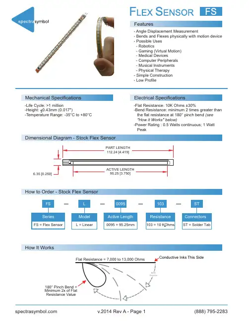
Features- Angle Displacement Measurement- Bends and Flexes physically with motion device - Possible Uses - Robotics- Gaming (Virtual Motion) - Medical Devices- Computer Peripherals - Musical Instruments - Physical Therapy - Simple Construction- Low ProfileMechanical SpecificationsElectrical Specifications-Life Cycle: >1 million-Flat Resistance: 10K Ohms ±30%-Bend Resistance: minimum 2 times greater than the flat resistance at 180° pinch bend (see "How it Works" below)-Power Rating : 0.5 Watts continuous; 1 Watt PeakDimensional Diagram - Stock Flex Sensor6.35 [0.250]How It WorksHow to Order - Stock Flex SensorSchematicsFollowing are notes from the ITP Flex Sensor Workshop"The impedance buffer in the [Basic Flex Sensor Circuit] (above) is a single sided operational amplifier, used with these sensors because the low bias current of the op amp reduces errer due to source impedance of the f lex sensor as voltage divider. Suggested op amps are the LM358 or LM324.""You can also test your flex sensor using the simplest circut, and skip the op amp.""Adjustable Buffer- a potentiometer can be added to thecircuit to adjust the sensitivity range.""Variable Deflection Threshold Switch- an op amp is usedand outputs either high or low depending on the voltage of theinverting input. In this way you can use the f lex sensor as aswitch without going through a microcontroller.""Resistance to Voltage Converter- use the sensor as theinput of a resistance to voltage converter using a dual sidedsupply op-amp. A negative reference voltage will give a positiveoutput. Should be used in situations when you want output at alow degree of bending."。
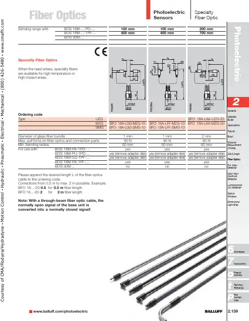
Fiber Optics2.139/photoelectricp76o Please append the desired length L of the fiber optics cable to the ordering code.Corrections from 0.5 m to max. 2 m possible. Example:BFO 18...-20-0.5for 0.5 m fiber length BFO 18...-20-2for 2 m fiber length Note: With a through-beam fiber optic cable, the normally open signal of the base unit is converted into a normally closed signal!Sensing range withBOS 18M-...-PD-...BOS 18M-...-1PF-...BOS 30M-...Ordering codeT ype UZG MZG SMG Diameter of glass fiber bundleMax. pull force on fiber optics and connection parts Min. bending radius For use with BOS 18M-PA-1PD-...BOS 18M-PU-1PD-...BOS 18M-GU-1PF-...BOS 18M-PA-1PF-...BOS 30M-...Specialty Fiber OpticsWhen the need arises, specialty fibers are available for high temperature or high impact areas.C o u r t e s y o f C M A /F l o d y n e /H y d r a d y n e ▪ M o t i o n C o n t r o l ▪ H y d r a u l i c ▪ P n e u m a t i c ▪ E l e c t r i c a l ▪ M e c h a n i c a l ▪ (800) 426-5480 ▪ w w w .c m a f h .c o mPhotoelectric Sensors2.140Please append the desired length L of the fiber optics cable to the ordering code.Corrections from 0.5 m to max. 2 m possible. Example:BFO 18...-20-0.5for 0.5 m fiber length BFO 18...-20-2for 2 m fiber length Note: With a through-beam fiber optic cable, the normally open signal of the base unit is converted into a normally closed signal!SpecialtyFiber OpticSensing rangeBOS 18M-...-PD-...BOS 18M-...-1PF-...BOS 30M-...Ordering codeT ype UZG MZG SMGDiameter of glass fiber bundleMax. pull force on fiber optics and connection partsMin. bending radiusFor use with BOS 18M-PA-1PD-...BOS 18M-GU-1PF-...BOS 18M-PA-1PF-...BOS 30M-...C o u r t e s y o f C M A /F l o d y n e /H y d r a d y n e ▪ M o t i o n C o n t r o l ▪ H y d r a u l i c ▪ P n e u m a t i c ▪ E l e c t r i c a l ▪ M e c h a n i c a l ▪ (800) 426-5480 ▪ w w w .c m a f h .c o mFiber Optics/photoelectric Sensing Range BOS 18M-...-PD-.../BOS 18M-...-1PF-...DiffuseBOS 30M-...RetroreflectiveBOS 18M-...-PD-.../BOS 18M-...-1PF-...BOS 30M-...Ordering code TypeUZG MZG SMGDiameter of glass fiber bundleMax. pull force on fiber optics and connection parts Min. bending radiusFor use with BOS 18M-PA-1PD-...BOS 18M-GU-1PF-...BOS 18M-PA-1PF-...BOS 30M-...Sn BOS 18M-PA-1PD-...with BOS 18M-...-1PF-...BOS 30M-...Range with BOS 18M-PA-1PD-...with BOS 18M-...-1PF-...BOS 30M-...Sensing distances referenced to Kodak gray card 90 %Reflexion.Diffuse with glass fiber optics used as retroreflective:Ranges are referenced to BOS R-1 reflector.When using as a retroreflective type, twice the sensing distance must be used as the object dead zone.Please append the desired length L of the fiber optics cable to the ordering code!Corrections from 0.5 m to max. 2 m possible.Example:BFO 18...-30-0.5for 0.5 m fiber length BFO 18...-30-2for 2 m fiber lengthC o u r t e s y o f C M A /F l o d y n e /H y d r a d y n e ▪ M o t i o n C o n t r o l ▪ H y d r a u l i c ▪ P n e u m a t i c ▪ E l e c t r i c a l ▪ M e c h a n i c a l ▪ (800) 426-5480 ▪ w w w .c m a f h .c o mPhotoelectricSensors2.142Specialty Fiber OpticSensing Range BOS 18M-...-PD-.../BOS 18M-...-1PF-...DiffuseBOS 30M-...RetroreflectiveBOS 18M-...-PD-.../BOS 18M-...-1PF-...BOS 30M-...Ordering code TypeUZG MZG SMGDiameter of glass fiber bundleMax. pull force on fiber optics and connection parts Min. bending radiusFor use with BOS 18M-PA-1PD-...BOS 18M-GU-1PF-...BOS 18M-PA-1PF-...BOS 30M-...Sn BOS 18M-PA-1PD-...with BOS 18M-...-1PF-...BOS 30M-...Range with BOS 18M-PA-1PD-...with BOS 18M-...-1PF-...BOS 30M-...Installation notethe adapter disk from the fiber optic cable !C o u r t e s y o f C M A /F l o d y n e /H y d r a d y n e ▪ M o t i o n C o n t r o l ▪ H y d r a u l i c ▪ P n e u m a t i c ▪ E l e c t r i c a l ▪ M e c h a n i c a l ▪ (800) 426-5480 ▪ w w w .c m a f h .c o mFiber Optics/photoelectric Rugged construction from the outside in UZG type Polyurethane jacket Strain reliefGlass fiber bundle -Enhanced chemical resistance -High flexibility -Does not get brittle in oils or coolantsMZG type Polyurethane jacket Strain reliefGlass fiber bundle -High temperature rating (-20...+170°C)-Crush resistant -Resistant to hot chipsBalluff BFO 18M series fiber optic cables are designed for use with BOS 18M and BOS 30M sensors. These rugged-duty cables are ideal for applications where high excess gain, enhanced chemical resistance, or high temperature solutions are needed.BOS 18M-GU-1PF-...BOS 18M-PU-1PD-...See Tubular section for technical dataBFO 18M SeriesC o u r t e s y o f C M A /F l o d y n e /H y d r a d y n e ▪ M o t i o n C o n t r o l ▪ H y d r a u l i c ▪ P n e u m a t i c ▪ E l e c t r i c a l ▪ M e c h a n i c a l ▪ (800) 426-5480 ▪ w w w .c m a f h .c o m。

O P T F L E X F简易操作手册The pony was revised in January 2021OPTIFLEX 2200 C/F两线制导波雷达(TDR)物位仪表测量液体和浆液的距离、液位、体积,也适用于粉料和固体颗粒本文件根据以下文件编辑整理,如有更改,恕不通知。
目录1开箱、交货范围...................................... 错误!未定义书签。
2 安装要点........................................... 错误!未定义书签。
3开盖与接线.......................................... 错误!未定义书签。
4就地显示和键盘操作.................................. 错误!未定义书签。
5 菜单操作........................................... 错误!未定义书签。
6 仪表安装时必需设置的内容(快速设置)............... 错误!未定义书签。
本手册是为现场接线、安装调试提供便捷途径。
详细内容请阅读随机光盘操作手册!1开箱、交货范围①转换器和天线②同轴套管,标配没有!③快速安装说明(英文版)④光盘(包含所有的文件)⑤开盖工具⑥保护帽,用于转换器维修时防止传感器顶部进水。
2 安装要点天线周围300mm半径内没有影响雷达波的机械结构件或受到物料冲刷,短节高度小于直径(h<d)。
3开盖与接线开盖取下外壳与前盖(或后盖)之间的紧固组件。
用开盖工具逆时针旋转前盖(或后盖),从刻度①---刻度②。
向上提出前盖(或后盖)③3.2接线二线制4--20mA回路供电信号接线,信号地③,设备地④分体型仪表传感器与转换器接线打开转换器与传感器盖子,用一根四芯帯屏蔽导线一一对应接线。
(防爆型仪表必须配科隆原厂导线)4就地显示和键盘操作正常显示状态设置显示状态①百分百显示⑤更新数据①菜单功能描述②显示内容:液位、距离等⑥测量值和单位②设置状态③报警信息⑦设备状态③菜单编号④位号⑧键盘面板按键定义:1号键2号键3号键4号键按键功能①液位、距离、体积等切换请注意:按住4号键3秒钟,显示语言转换为英语。
3B SCIENTIFIC ®PHYSICS1Instruction Sheet10/15 Hh∙To avoid permanent damage to the integrated load cell, do not exceed the maximum permitted applied force of ± 150 N!∙ Do not allow the sensor unit to fall onto ahard surface from a height greater than 1 m!∙ The ± 150 N force sensor must only beused for educational purposes!The ± 150 N force sensor is not suitable forsafety-related applications! Sensor box incorporating a load cell and a force sensor working on the foil strain-gauge principle.Push-buttons allow a choice between two measurement ranges, ± 5 N and ± 50 N.The measurement range selected is indicated by an LED beside the relevant button.A tare function (compensation of the no-load reading) is provided for both measurement ranges.The bent clamping rod that is provided allows the sensor box to be mounted at 90°.The screw hook with M4 thread that is provided can be replaced by any other attachment with an M4 thread.The sensor box is designed to be recognised automatically by the 3B NET logTM . 1 Force sensor, ± 50 N1 Clamping rod with 90° bend,l 1 = 150 mm, l 2 = 95 mm, d = 12 mm1 Screw hook with M4 thread, eye diameter 20 mm1 8-pin mini-DIN connecting cable, length 60 cm1 Instruction sheet2Measurement ranges: 0 ... ± 5 N, 0 ... ± 50 N Sensor type: load cell with foilstrain-gaugeNon-linearity: typically ± 0.04% oftotal measurement rangeResolution: 0.01 N in 5 N range 0.1 N in 50 N range Tare compensation: max. ± 50 N Max. frequency: typically 20 Hz Max. diameter of supporting rod: 13 mm∙Place the sensor box near the experiment and connect it to the point that will apply the forces; if necessary use the bent clamping rod.∙ Screw in the threaded hook if appropriate,or alternatively replace it by another attachment for applying force.∙ Connect the sensor box to one of the twoanalogue inputs (A or B) of the 3B NET log TM using the mini-DIN cable provided.∙ Wait for the sensor recognition message(“Probe Detect”).∙ Choose the appropriate measurementrange.∙ If necessary, press the tare button to applycompensation.The tare compensation depends on the position in which the force sensor is used, and it must be reset for each new experimental set-up!∙ Carry out the force measurement and readthe force value in the display of the 3B NET log TM .Measurements on simple harmonic oscillations.Observation of frictional forces. Investigations of Hooke’s Law.Measuring the forces on a truck on a track.Investigation of the forces in pulley systems.Measuring the acceleration in a damped mass-and-spring oscillating system Equipment needed:1 3B NETlogTM @ 230 V 1000540 or1 3B NETlogTM @ 115 V 1000539 1 3B NETlabTM 1000544 1 Force sensor, ± 50 N 1000557 1 Tripod stand 1002835 1 Stainless steel rod, 750 mm 1002935 1 Helical spring, 5 N/m 1000741 1 100 g weight, from set of weights 1003214∙ Set up the experiment as shown in fig. 1. ∙ On the 3B NET lab TM , open the application(template) for the experiment with the ± 50 N force sensor.∙ Attach the weight to the helical spring andhang the spring on the force sensor. Ensure that there is nothing hindering the oscillation motion.∙ Pass the connecting cable of the forcesensor over the sensor and coil it around the stand as shown in Figure 1.∙ Steady the weight by hand so that it ismotionless on the helical spring.∙ Select the ± 5 N measurement range.∙ Press the tare button of the force sensorand set the pointer to zero in the display of the 3B NET log TM .∙ Pull the weight down manually to the levelof the stand base and release it.∙ Start the recording of the force curve onthe 3B NET lab TM (see fig. 2). ∙ Interpret and evaluate the curve.3B Scientific GmbH • Rudorffweg 8 • 21031 Hamburg • Germany • Subject to technical amendments.© Copyright 2015 3B Scientific GmbHFig. 1 Measuring the oscillations of a weakly-damped mass-and-spring systemFig. 2 Oscillations of a weakly-damped mass-and-spring system displayed on the screen of the 3B NET lab TM。
使用说明书FLEXI-FLOW™Compact文档号:9.17.158版本号:D日期:2023年1月30日注意事项安装使用本产品前,请仔细阅读本文档。
如未按照操作手册操作,很可能造成人身伤害和/或设备损坏。
请妥善保存本文档以备将来参考。
版权所有©2023Bronkhorst High-Tech B.V.版权所有。
Bronkhorst®是Bronkhorst High-Tech B.V.的注册商标。
所有其他商标分别是其各自所有者的财产。
免责申明本文档中的插图表示正确操作的一般注意事项。
插图简单地反映了实际情形,可能与实际产品不同。
Bronkhorst High-Tech B.V.保留修改或改进旗下产品,更新文档内容相关权利,进行该等事宜前,无需通知任何特定个人或组织。
工作前,请检查Bronkhorst网站是否有本文档的更新版本。
使用说明书如中英文版本内容存在差异,皆以英文版本为准。
本文档的符号重要信息。
若忽略该信息,很可能导致设备损坏与人身伤害的风险增加。
提示信息、有用信息和注意事项。
该信息可帮助用户使用仪器和/或确保仪器以最佳性能运行。
更多信息参见参考文档,如需获取,可访问指定网站下载,也可联系Bronkhorst代表获取。
服务若对产品有任何疑问,或发现产品不符合订购时约定的规格,请联系Bronkhorst代表。
无论因何原因联系Bronkhorst代表时,请务必备妥产品序列号,以便我司快速有效地帮助您。
如需了解Bronkhorst®和全球服务地址的最新信息,请访问我司网站:对于我司产品,您有什么疑问吗?我司销售部非常乐意为您提供帮助,助您选购可适用您的具体应用场景的正确产品。
如需联系我司销售部,可发邮件至:********************如遇售后问题,或需要帮助和指导,可通过电子邮件联系我司客户服务部:*************************无论您位于世界哪个时区,我司客户服务部专家均可针对您的特定需求作出响应,或采取适当后续行动。
F i b e r I n s p e cFOCIS Flex – Fiber Optic Connector Inspection System Easy, Fast, Compact, Tether-freeU.S. Patent 9,217,688FOCIS Flex makes connector inspection simple, fast, and convenient. With the press of a single button, FOCIS Flex auto-focuses, captures and centers the end-face image, applies Pass/Fail rules, displays image and Pass/Fail results, saves results internally and/or wirelessly transfers data to a paired FlexScan OTDR or a smart device. It is fast, small, and easy to use to enable 100% connector inspection. Independent, untethered operation: With rechargeable battery and integrated display, FOCIS Flex can be used independently without requiring an external OTDR or display unit.Optional pairing with FlexScan OTDR or smart devices : Captured images and Pass/Fail results can be immediately displayed and easily saved on either paired FlexScan OTDR or a smart device equipped with the AFL’s free FOCIS Flex App. This capability enables inspection results to be included in reporting and archiving.Save results internally or externally: FOCIS Flex internally stores up to 10,000 results using file-naming capabilities similar to those of the FlexScan OTDR. A micro-USB port supports fast upload of internally stored results to PC and ensures your FOCIS Flex software can be updated to the latest features and supported languages.Wide range of adapter tips: Interchangeable adapter tips support connector inspection for a wide range of both single-fiber and multi- fiber patchcords and bulkhead-mounted connectors having either PC or APC polished end-faces.Bundled kits for significant savings: FOCIS Flex is available in kits that include a Basic license for Test Result Manager (TRM ® 3.0), user-selected adapter tips and cleaning supplies, and a soft carry case.Easy reporting and archiving: Included Test Result Manager (TRM 3.0) provides data processing and reporting locally via a PC. The FOCIS Flex mobile App is available for free download from Google play or App Store for sharing data with smart devices.Features•1-button to auto-focus, center, capture, analyze, and save •IEC, IPC, and user-defined pass/fail analysis •Untethered, compact, hand-held inspection •Use independently or pair with OTDR•Save 10K results internally or share via WiFi or USBApplications•Inspect connectors on patch cords or in bulkhead adapters •Optical network installation, troubleshooting, and maintenance •Inspect MPO/MTP multi-fiber connectors•Assure critical fiber infrastructure performs properly•Keep fiber connections working at optimal performance levels •Verify proper connector cleaning practices are being usedFOCIS Flex – Fiber Optic Connector Inspection System Easy, Fast, Compact, Tether-freeU.S. Patent 9,217,688Specifications aOPTICAL PERFORMANCEField of View (viewed on FOCIS Flex)Captured, Zoomed Out: 560 x 600 µm;Captured, Partially Zoomed In: 360 x 390 µm;Captured, Fully Zoomed In: 180 x 195 µm Field of View (Viewed on a PC)Stored, Zoomed Out: 700 x 525 µm;Stored, Fully Zoomed In: 240 x 180 µm Manual Detection Capability (minimum)Auto Analysis Resolution Captured Image Size (Pixels)648 x 480 VGA; Images stored internally in three .JPG files, one at each FOVOPERATING FEATURES Auto-focus and manual focus Auto-centering after capturePass/Fail AnalysisIEC 61300-3-35 (2015), IPC and user-defined criteria Image Capture and File Storage Capacity File Format (Image and Pass/Fail Results)Bluetooth Characteristics SPP to FlexScan and FlexTester OTDRs; IAP to iOS devices USB Characteristics USB 1.1 mass storage deviceSupported LanguagesPHYSICAL AND POWER CHARACTERISTICS Display size, type, resolution Battery TypeBattery Operating Time (typical)Recharge TimePower Save FeaturesAC Charger voltage, frequency, current ENVIRONMENTAL CHARACTERISTICS Notes:a. All specifications valid at 23°C ±2°C (73.4°F ±3.6°F).Pass/Fail results in seconds: With the press of a single button, FOCIS Flex auto-focuses, captures and centers the end-face image, applies Pass/Fail rules, displays image and Pass/Fail results. Captured Pass/Fai results are easily viewed in either Image or Table view.Image view shows end-face image with Pass/Fail region overlay , failing scratches/defects highlighted in red , and passing scratches/defects highlighted in green.Table view shows analysis rule applied to determine Pass/Fail, analysis Zone IDs (A, B, C, D), scratch analysis results for each zone, and defect analysis results for each zone.FOCIS Flex – Fiber Optic Connector Inspection System Easy, Fast, Compact, Tether-freeU.S. Patent 9,217,688FOCIS Flex Adapter Tips (Contact AFL for adapter tips for other connector types)FlexScan OTDR PRO and BIPM Kits with FOCIS Flex PRO Kits include the following items:•FlexScan with accessories (AC charger, carry strap, SC/2.5 mm connector adapters, TRM ® 3.0 Advanced Test Results Manager, carry case) •FOCIS Flex Fiber Optic Connector Inspection System with accessories (AC charger, USB cable, soft carry case/holster) •Two user-selected adapter tips and one user-selected One-Click Cleaner •150 m Fiber Ring (launch cable) with user-specified connectorsComplete kits expand on PRO Kits by adding bend insensitive fiber identifier with optional power meter (OFI-BIPM).See FlexScan data sheet for FlexScan PRO and Complete Kit ordering information.Ordering InformationFOCIS Flex – Fiber Optic Connector Inspection System Easy, Fast, Compact, Tether-freeU.S. Patent 9,217,688QualificationsContact ******************* to schedule a demonstration or learn how to buy.Visit /Test to learn more about FOCIS Flex.International Sales and Service Contact Information available at /Test/Contacts.Test Management and Reporting SoftwareRecommended ProductsFlexScan ® FS300 (quad) and FS200 (single-mode) OTDRs • SmartAuto ® 1-button automated testing for fast results • LinkMap ® color-coded icons for easy troubleshooting• FleXpress ® mode (FS200) completes OTDR test in <5 seconds!• Integrated Source, Power Meter and VFLOFI-BIPM Optical Fiber Identifier • World class signal sensitivity• Trigger lock, positive stop for optimum detection • Integrated optical power meter optionFS200FS300。
1 安全提示1.1 被授权的仪表操作人员处于安全考虑,在这本说明书中所介绍的各种操作,需要经过培训和授权的技术人员来完成。
1.2 应用VEGAFLEX60系列超声波传感器用于连续物位测量。
1.3 使用错误的警示如果应用不正确或不符合规定,从应用角度讲,由于安装或调试错误,容器会溢出介质或损坏设备。
1.4 安全介绍在安装和操作仪表的时候,需要注意有关的安全规定(比如:在德国需要符合VDE-规定)。
1.5 CE – 认证VEGASON60系列经过CE认证,满足NAMUR-要求NE21。
CE-认证根据以下标准:• EMVG:-Emission EN 61326:1997(A级)61326:1997/A1:1998- ImmissionEN• NSR: EN 61010-1: 20011.6 仪表兼容性符合NAMUR NE53VEGAFLEX60系列传感器符合NAMUR要求NE53。
VEGA的仪表一般都是向上、向下兼容的。
• 传感器-软件到VEGAFLEX-HART、PA或FF的DTM文件• VEGAFLEX的DTM文件到调试软件PACTware• 调整模块PLICSCOM到传感器软件传感器的基本功能的参数调整可以不依赖于软件版本。
功能的范围取决于每个组件的软件。
VEGAFLEX60系列的软件版本可以通过以下方式知道:• 通过软件PACTware TM• 电子部件的铭牌• 通过调整模块PLICSCOM1.7 防爆应用的注意事项对于防爆应用,要注意防爆安全规定。
每个防爆仪表都会随附防爆合格证,要注意防爆参数。
1.8 环保事项环境保护现在已经成为最为紧要的任务。
因此VEGA公司也建立了完善的环保管理体系,且获得EN ISO14001认证。
请您帮助我们,完成环保的使命,见以下两章:• “仓储和运输”• “清除废料”2 产品介绍2.1 构造供货范围• 导向微波式传感器VEGAFLEX60系列• 文件资料-此操作说明书-您订购的各类相应的许可证,比如:如果您购买的是防爆型的仪表,随附防爆许可证组件• 过程连接和探头• 外壳带电子部件• 外壳罩盖,可选带调整显示模块PLICSCOM1 外壳罩盖和下面的调整显示模块PLICSCOM(可选)2 外壳,带电子部件3 过程连接2.2 工作原理应用范围VEGAFLEX60系列包括缆式、棒式、同轴管式多种测量电极,用于连续地物位测量。
Proximity Sensors Capacitive • Level sensor for solid, fluid or granulated substances• Adjustable sensing distance: 4-12 mm • Multi voltage supply: 20.4 to 255 VAC/DC • SPDT relay output• Time delay on operate or release • Time delay options up to 10 minutes• VC11/12RTM24: With adjustable time delay • VC12RNM24: Without time delay • Cable versionsProduct DescriptionCapacitive sensor in thermo-plastic polyester for mount-ing in a PG 36 screw gland. Available with adjustable sensing distance and with/ without built-in time delay(ON or OFF delay). The relay output ensures that the load can be driven direct-ly. Ex c ellent for use in the agricultural area (detection of grains, fluids etc.).Supply voltage Ordering no. Ordering no. Ordering no. With ON delay With OFF delay Without time delay24- 230 V AC/DC VC11RTM2410M VC12RTM2410M VC12RNM24Type SelectionThermoplastic PolyesterTypes VC11RTM24, VC12RTM24, VC12RNM24SpecificationsVC11RTM24, VC12RTM24, VC12RNM24Specifications (cont.)DimensionsTrimmer VS DistanceTrimmer VS DelaytimeMode of OperationVC11RTM24 (See operationdiagram). Power supply is applied to the sensor (BN and BU wires). When the target is not present, the relay operates (connection be t ween BK and YE wires) and LED lights. When the target is detected the time measurement starts and LED flashes. After expiration of the set time (0-10 min.), the relay releases (connection between BK and GY wires) and LED turns off. The relay remains released as long as the target is detected.VC12RNM24 (See oper-ation diagram). Power sup-ply is applied to the sensor (BN and BU wires). The relay operates (connection be t ween BK and YE wires) and remains ON until thetarget is detected. After activation of the sensor the relay releases (connection between BK and GY wires.)VC12RTM24 (See operation diagram). Power supply is applied to the sensor BN and BU wires) and time meas-urement starts. When the set time has expired (0-10 min.) the relay operates (connection between BK and YE wires) and remains connected until the target isdetected. After activation of the sensor the relay releases (connection between BK and GY wires). As soon as the target is not present again the time measurements of the set time starts.VC11RTM24, VC12RTM24, VC12RNM24AdjustmentWiring DiagramDetection DiagramOperation DiagramsPower supply (BN - BU wires)Target detectedRelay ON (BK - YE wires)LED indicationPower supply (BN - BU wires)Target detectedLED indicationVC12RTM24Power supply (BN - BU wires)Target detectedLED indicationDelivery Contents• Capacitive switch: VC11/12• Installation instruction • Screwdriver• Packaging: Plastic bagVC11RTM24, VC12RTM24, VC12RNM24。
智慧型流动感测器使用说明书■ 中文繁体M-FL6/F E 6-C N-V1.4FL/FE系列4. 感测器插入深度: 至少保证深度≥12mm, 使用转接头(需单独 订货)可确保正确的深度。
注意:感测器探头不可碰到管壁。
搭配本防爆产品,否则请勿使用。
7. 产品外壳所安装的管道须与 等电位接电系统正确连结。
8. 警示语: 爆炸性环境存在时,请勿打开。
107108端子图及系统连線PIN 1:L +, 电源正极(BN )PIN 2:P , 编程線(WH )PIN 3:L -, 电源负极(BU )PIN 4:PNP /NPN 输出(BK )接線圖接線圖109110112前流动,並设定该值作为LED 的最小显示值。
在正常的运作中,当流动低於该值时(或当它停止流动时),第一个綠色的LED (LED 0 )闪烁。
(见下图)並高开关点=流速減小时快速反应。
減小开关点:使闪烁和亮的LED 移到最大设置值,然后循环从最小设置值重新开始溢出:如果闪烁和亮的LED 超过最大设置值,循环从最小设置值重新开始113114设定前请先解锁。
电源时,键盘处於锁定状态。
加锁:该设备具有自动锁定按键功能,当处於运行模式时,如检测到2分钟内未有按键按下,则自动锁定键盘,正常检测流速的变化和显示,並可报警且输出控制量。
解锁:同时按下两个按键,並持续10秒,中间两个綠色LED 灯闪烁提示则键盘锁解开,用户可通过键盘进行调节相关参数。
116在0~100cm/s范围内, 调整到高流动值时,滞后为2~4(适用於水)。
cm/s曲線调整到高於备注:标准探棒长度约45mm ,另有加长型探棒长度100型号mm/200mm,和防腐蚀型钛合金探棒供客户选购。
1191204. 针对较低流速,可选购方形 低流量三通US0029。
为避免故障,应注意感测器和弯头,阀门及横截面有变化之处或诸如此类地方的最小距离见右图:拧紧,拧紧扭矩为1.5Nm 。
6. 请选购伊玛合格的防爆線搭配本防爆产品,否则请勿使用。
Flexiforce传感器分类介绍及其应用
一、Flexiforce 传感器
Flexiforce是一种超薄和挠性印刷电路,可很方便集成多种运用。
由于Flexiforce 像纸一样薄的结构,可弯曲和测力特性可用来测两表面之间的压力,并且能够在一些特殊环境进行测力。
Flexiforce 比其它薄膜测力产品有更好的特性、线性、磁滞、飘移、温度灵敏度。
传感的有效区域是传感器末端的直径为0.95cm的圆。
Flexiforce 由两层衬底构成。
这种衬底由聚脂纤维薄膜组成(高温传感器用的是聚酰亚胺构成)。
在每一层上运用一种导体材料(银),再加一层对压力敏感的墨水。
然后用粘合剂把两层衬底压在一起,形成了传感器。
墨水外的银边表示了对压力敏感的区域。
从敏感区域引出两个银线作为导线。
Flexiforce 传感器尾端选配一个可焊接的公的方针接头以方便连接到电路。
两边的输出线是有效的,中间的是无效的。
传感器的长度可选6cm、12cm、18cm或由客户定制。
在电路中传感器相当于一个可变电阻。
当没有负载时,传感器呈高阻状态(>5MΩ),当有负载时,电阻下载。
接一个欧姆表可以看见当在敏感区域施加外力时电阻的变化。
Flexiforce 需保存在温度-9°C74°C之间。
二、标准Flexiforce传感器
标准A201传感器有下列量程供选择:
Sensor A201-1 (0-1 lb)(0-4.5N)
Sensor A201-25 (0-25 lb)(0-112.5N)
Sensor A201-100 (0-100 lb)*(0-445N)
如果要测量大于100lb的力可降低供电电压和降低反馈电阻(最小1KΩ min)可参看驱动电路图。
三、高温Flexiforce传感器
高温HT201传感器有下列量程供选择:
HT201-L Low: 0-30lb (133N)
HT201-H High: 0-100lb (445N)
四、运用
Flexiforce传感器有非常多的用法。
典型的运用就是把检测的压力转化成电压信号输出。
校准也必须去做,就是把输出信号和相应的压力的大小对应。
根据配置,灵敏度依然可以进行调节。
典型电路如下图:
在该电路中,用+/-5V的电压激励,反相比例放大电路结构,基于传感器电阻和反馈电阻的变化产生模拟信号输出。
模数转换器也可把模拟信号转为数字信号输出。
灵敏度由反馈电阻Rf和电压VT 进行调整。
降低反馈电阻和电压会使灵敏度下降,但可使量程增大。
用途简介:
医疗用途:牙齿咬合力测量;病人组织插管测力;临床大夫触力检验测量;心肺复苏、人工呼吸救护训练(CPR)(位置、深度、频率)触力测量;诊断设备研究肌肉关节活动情况;发音矫正;智能鞋垫进行走路平衡能力测控(老年人走路摔倒报警);重症病人,老人监护报警等。
汽车运用:乘员探测;安全气囊对乘员压力;拖车刹车控制。
休闲娱乐运用:体育用具;健身器材;握力测量;GOLF训练。
工业运用:安全装置;包装与密封;自动化生产;滚动轴承;电缆卷轴;电脑芯片。
其它:动物或人类咬力测量;触力设备;抓力;库存管理;设备监控;机器人;等等。
传感器载荷考虑因素
下面的传感器负载运用指导适合任何运用,以帮助您取得精确的测量结果。
后面传感器性能参数表对您获取准确的传感器数据也是至关重要的。
一、传感器负载
Flexiforce传感器整个传感区域被当成一个独立的接触点。
因此,负载应均匀分布在传感区域以保证准确和重复的测力数据。
如果负载分布改变就会轻微地改变传感器的读数。
(传感器传感区域就是银线包围中间的部分)
施加负载的持续也很重要,并保证每次是同样的方式;
不要让传感区域外面的部分也支持负载;
如果要测的负载大于传感区域,那么可使用一个圆盘(一般由硬材料构成,并小于传感区域),使负载通过圆盘压住传感区域,注意不要压住传感区域的边缘。
加的力需垂直于传感区域的平面。
如果施加剪切的力会降低传感器的寿命。
如非要加这样的力,需要有弹性材料进行保护。
如果把传感器放在一个表面,可使用带子或胶水。
注意不要把胶水沾在了传感区域,如果一定要的话,要保证涂的均匀,否则一些高点会变成负载。
二、饱和值
饱和值就是输出不再随施加的力而变化的点。
每个传感器的饱和值会印在包装盒或传感器上和灵敏度在一起。
饱和值在上面的运用电路中和反馈电阻Rf有关,当降低反馈电阻Rf时可降低灵敏度,但可增大量程,也就是可增大饱和值。
注意在测试中不要让外力到达饱和值。
三、传感器适应使用
在测试或校准前,让传感器适应或适用对取得准确的测量数据是必须的。
它可以帮助减少磁滞和飘移。
对于新传感器需要让它用一段时间以适应环境。
让传感器适应使用,可采用110%的力加在传感器上,让传感器稳定,再移动负载。
重复这个过程四到五次。
传感器和测试材料的接触面需保持和测试和校准时一致。
(重要:在校准和使用前,传感器必须经过适应使用)
校准
校准就是让传感器的输出和真正的测力值建立一个对应关系如磅或牛顿。
校准时,可采用一已知力加在传感器上,然后把传感器的阻值和力值对应起来。
用一些和测试时接近的力值,重复进行这个校准的过程。
力和电导(1/R)的对应图如下。
一个线性的对应关系可从图中看出。
然后,你可用传感器的输出值来决定你的测力的大小了
电阻曲线
电导曲线
校准指导:
在校准传感器可参考下列指导:
有与实际测试中相近的力来进行校准。
(用已知的力,如砝码或测力机)。
如在校准中用圆盘那么在测试中也用。
在校准时避免和测力饱和值接近,如在很少的力就饱和了,那么就调整灵敏度。
在感应区域内,均匀放置负载。
负载分布改变,结果会有轻微变动。
测试和校准时温度需保持一致。
传感器性能指标描述:
有一些性能指标会影响到传感器的测量结果。
这里对每个指标进行一些描述,以帮助减少不必要的影响。
重复性:对于同样多次施加的力,传感器能保持显示数据的一致性。
通常,我们建议通过对传感器进行适应“训练”后,再进行测试或校准。
线性:指传感器针对负载的响应偏移超过了传感器的实际量程。
校准可以尽量使输出保持线性。
Flexiforce传感器的输出线性在+/- 3%以内。
Flexiforce高温传感器的线性可以做到满量程的1.2%。
磁滞:在加负载和移除负载时,传感器的实际输出值的差异。
在静态时,在负载增加时,磁滞是非常小的。
但在负载一会小一会大时,会有磁滞引起的误差。
飘移:指在施加力后一段时间,输出会有相应的变化。
如果在一个固定的负载下,输出电阻持续减少,输出就会慢慢增大。
在校准时考虑到飘移的因素,可减少其影响。
最简单的方法是保证校准时和实际测试时的时间段一致。
温度灵敏度:通常,输出在大负载情况下会随温度升高而变化。
为保证准确性,校准和测试时要保持一致温度。
如果不一致,最好在不同的温度下都做一校准,并以保存备用。
寿命:寿命是根据你的使用情况而定。
一般传感器可以反复使用,除了在一些极端情况下:如承受硬边或冲击力。
经测试,对一个50lb的Flexiforce传感器可以使用一百万次。
物理损伤自然会降低它的寿命。
保持传感区域清洁,否则脏物会引起测量不准,及过早地进入饱和状态。
传感器性能指标
标准Flexiforce传感器(型号:A201)
高温Flexiforce传感器。