CHAP4-6C-晨华工作站
- 格式:pdf
- 大小:318.28 KB
- 文档页数:58
1、电源在AT或ATX之间变换时,主板可能无法开机,需BIOS放电或power switch短接2、机箱电源一定要接地,否则机箱上会带110V感应电压,电流在1mA之内3、使用PIII CPU时,需上导热硅脂,否则系统不稳定,易死机4、带网卡的CPU卡,安装winNT Workstation 4.0,在安装网卡前,先做如下处理,否则“事件查看器”会出现“存储器空间不足提示”一、a、进入CMOS,PnP/PCI ConfigurationsPNP OS Installed >[NO]Resources Controlled By > [Manual] 保存重启b、安装完网卡后,再打一次SP6补丁即可c、这时CMOS可更改为其它设置二、或网卡驱动应先于Service Pack来安装.否则有时会不能启动Workstation Service,并且报错:存储空间不足.出现这种错误时,可以重新安装一下Service Pack5、主板不开机,换BIOS或检查电池电量、CMOS放电检查电源PG、5VSB+0.01V6、KB、MS线最长5米,HDD IDE线最长75cm(标准45mm)。
nupro760LV可以支持到20米KB、MS延长线7、CPU卡直接使用LCD时,在系统关机时LCD屏闪动历害,可把屏幕“刷新频率”设高为:75或85Hz8、主板带两个网口时使用WinNT4.0+SP6.0时,网络要设置为两个网段,与其相连的机器也要设置为两个网段。
否则网口只能使用一个。
9、主板安装OS过程死机,除主板、内存及HDD外,也可能是CPU坏或HDD线坏如果是安装win2000出现*.DLL文件无法复制,先考虑内存坏,依次光盘、CDROM、HDD10、win98 SE无法关机或不能重启a、BIOS配置不正确。
在PnP/PCI Configurations选项中,有一项Assign IRQ VGA,如果你装的是Win98SE版本,关不了机,跟这个选项可能有关,要把它打开b、打win98简体关机补丁c、msconfig中“禁用快速关机”win98或win98SE开始不能安装或过程中死机A、如无软驱,可增加一个软驱B、BIOS中软驱设置为无11、在使用ATX电源时,也可当AT电源使用,但效果可能会不好,最好不要使用。


CN2600Series8and16-port RS-232/422/485terminal servers with dual-LAN redundancyFeatures and Benefits•LCD panel for easy IP address configuration(excluding wide-temperaturerange models)•Dual-LAN cards with two independent MAC addresses and IP addresses•Redundant COM function available when both LANs are active•Dual-host redundancy can be used to add a backup PC to your system•Dual-AC-power inputs(for AC models only)•Real COM/TTY drivers for Windows and Linux•Universal high-voltage range:100to240VAC or88to300VDCCertificationsIntroductionRedundancy is an important issue for industrial networks,and various types of solutions have been developed to provide alternative network paths when equipment or software failures occur.“Watchdog”hardware is installed to utilize redundant hardware,and a“Token”-switching software mechanism is applied.The CN2600terminal server uses its built-in Dual-LAN ports to implement a“Redundant COM”mode that keeps your applications running uninterrupted.Dual-LAN RedundancyThe CN2600has two separate LAN ports that can be connected toseparate LAN networks.Dual-LAN redundancy involves setting uptwo separate physical networks to connect the PC host with theCN2600(the PC host also requires two LAN cards).If one connectionfails,the PC host can still communicate with your serial devices overthe alternative LAN connection.Redundant COMMoxa offers“Redundant COM,”an easy-to-use application to providean alternative solution for network redundancy.When the CN2600receives a data packet from a connected device,two identical datapackets are sent over two independent LAN connections to preventlost data packets if one LAN connection becomes unavailable.TheCN2600software is programmed to automatically discard duplicatedata packets.Dual-host RedundancyThe CN2600’s dual-LAN cards can also be used to set up“dual-host”redundancy.In this case,both networks(LAN A and LAN B in the figure)are connected to two different hosts.If either of the two hosts shuts down unexpectedly,the other host will still be able to communicate with serial devices connected to the CN2600.Dual-AC Model SupportedDual-power redundancy uses two power inputs and redundantinternal power supplies to ensure that all of the CN2600’s functionswill be available,even in the event of power circuit failures. AppearanceSpecificationsEthernet Interface10/100BaseT(X)Ports(RJ45connector)2Magnetic Isolation Protection 1.5kV(built-in)Ethernet Software FeaturesConfiguration Options CN2610-8/CN2610-16:Serial Console,Telnet Console,Windows Utility,Device SearchUtility(DSU)CN2650-8/CN2650-16/CN2600-2AC models:Serial Console,Telnet Console,WindowsUtility,Device Search Utility(DSU),Web console(HTTP/HTTPS)Management ARP,BOOTP,DDNS,DHCP Client,DNS,HTTP,IPv4,SMTP,SNMPv1/v2c/v3,TCP/IP,Telnet,UDP,ICMP,SLIPMIB MIB-IISecurity HTTPS/SSL,RADIUS,SSH,PAP,CHAPUnicast Routing RIPV1/V2,Static RouteWindows Real COM Drivers Windows95/98/ME/NT/2000,Windows XP/2003/Vista/2008/7/8/8.1/10(x86/x64),Windows2008R2/2012/2012R2(x64),Windows Embedded CE5.0/6.0,Windows XPEmbeddedLinux Real TTY Drivers Kernel versions:2.4.x,2.6.x,3.x,4.x,and5.xFixed TTY Drivers SCO UNIX,SCO OpenServer,UnixWare7,QNX4.25,QNX6,Solaris10,FreeBSD,AIX5.x,HP-UX11i,Mac OS XAndroid API Android3.1.x and laterSerial InterfaceConnector8-pin RJ45No.of Ports CN2610-8models:8CN2610-16models:16Serial Standards CN2610models:RS-232CN2650models:RS-232,RS-422,RS-485Operation Modes Real COM mode,TCP Server mode,TCP Client mode,UDP mode,RFC2217mode,Terminal mode,Reverse Telnet mode,PPP mode,DRDAS mode,Redundant COMmode,DisabledBaudrate50bps to921.6kbpsData Bits5,6,7,8Stop Bits1,1.5,2Parity None,Even,Odd,Space,MarkFlow Control None,RTS/CTS,DTR/DSR,XON/XOFFIsolation CN2650I Series:2kVRS-485Data Direction Control ADDC®(automatic data direction control)Pull High/Low Resistor for RS-4851kilo-ohm,150kilo-ohmsTerminator for RS-485120ohmsConsole Port RS-232(TxD,RxD,GND),8-pin RJ45(19200,n,8,1)Serial SignalsRS-232TxD,RxD,RTS,CTS,DTR,DSR,DCD,GNDRS-422Tx+,Tx-,Rx+,Rx-,GNDRS-485-4w Tx+,Tx-,Rx+,Rx-,GNDRS-485-2w Data+,Data-,GNDPower ParametersNo.of Power Inputs CN2600Series:1CN2600Series-2AC models:2Input Current CN2600Series:130mA@110VACCN2600Series-HV models:200mA@88VDCInput Voltage AC models:100to240VAC,47to63HzDC models:110VDC(88to300VDC)ReliabilityAutomatic Reboot Trigger Built-in WDTAlert Tools Built-in buzzer and RTC(real-time clock)Physical CharacteristicsHousing MetalInstallation19-inch rack mountingDimensions(with ears)480x198x45.5mm(18.9x7.80x1.77in)Dimensions(without ears)440x198x45.5mm(17.32x7.80x1.77in)Weight CN2610-8/CN2650-8:2,410g(5.31lb)CN2610-16/CN2650-16:2,460g(5.42lb)CN2610-8-2AC/CN2650-8-2AC/CN2650-8-2AC-T:2,560g(5.64lb)CN2610-16-2AC/CN2650-16-2AC/CN2650-16-2AC-T:2,640g(5.82lb)CN2650I-8:3,907g(8.61lb)CN2650I-16:4,046g(8.92lb)CN2650I-8-2AC:4,284g(9.44lb)CN2650I-16-2AC:4,423g(9.75lb)CN2650I-8-HV-T:3,848g(8.48lb)CN2650I-16-HV-T:3,987g(8.79lb)Environmental LimitsOperating Temperature Standard Models:0to55°C(32to131°F)Wide Temp.Models:-40to75°C(-40to167°F)CN2650-HV-T Models:-40to85°C(-40to185°F)Storage Temperature(package included)Standard Models:0to55°C(32to131°F)CN2650-8-2AC-T/CN2650-16-2AC-T:-40to75°C(40to167°F)CN2650I-8-HV-T/CN2650I-16-HV-T:-40to85°C(-40to185°F) Ambient Relative Humidity5to95%(non-condensing)Standards and CertificationsEMC Non-I models:EN55032/24-I models:EN55032/35EMI CISPR32,FCC Part15B Class AEMS AC models:IEC61000-4-2ESD:Contact:8kV;Air:15kVIEC61000-4-3RS:80MHz to1GHz:10V/mIEC61000-4-4EFT:Power:4kV;Signal:2kVIEC61000-4-5Surge:Power:2.5kV;Signal:1kVIEC61000-4-6CS:150kHz to80MHz:3V/m;Signal:3V/mIEC61000-4-8IEC61000-4-11DIPsHVDC models:IEC61000-4-2ESD:Contact:4kV;Air:8kVIEC61000-4-3RS:80MHz to1GHz:3V/mIEC61000-4-4EFT:Power:4kV;Signal:2kVIEC61000-4-5Surge:Power:2kV;Signal:1kVIEC61000-4-6CS:150kHz to80MHz:3V/mIEC61000-4-8Safety Non-I models:UL60950-1-I models:UL62368-1Vibration IEC60068-2-6Freefall IEC60068-2-32DeclarationGreen Product RoHS,CRoHS,WEEEMTBFTime CN2610-8:831,925hrsCN2610-16:639,332hrsCN2610-8-2AC/CN2650-8-2AC:773,268hrsCN2610-16-2AC:604,346hrsCN2650-8:657,123hrsCN2650-16:457,175hrsCN2650-16-2AC:442,699hrsCN2650I-8/CN2650I-8-2AC/CN2650-8-2AC-T:190,562hrsCN2650I-16/CN2650I-16-2AC/CN2650-16-2AC-T:115,887hrsCN2650I-8-HV-T:191,326hrsCN2650I-16-HV-T:116,924hrsStandards Telcordia(Bellcore)Standard TR/SRWarrantyWarranty Period5yearsDetails See /warrantyPackage ContentsDevice1x CN2600Series terminal serverInstallation Kit1x rack-mounting kitCable1x RJ45-to-DB9console cable1x power cord,suitable for your region(AC models) Documentation1x quick installation guide1x warranty cardDimensionsOrdering InformationModel Name Serial Standards No.of Serial Ports Serial Connector Isolation No.of PowerInputsPower Input Operating Temp.CN2610-8RS-23288-pin RJ45–1100-240VAC0to55°C CN2610-16RS-232168-pin RJ45–1100-240VAC0to55°C CN2610-8-2AC RS-23288-pin RJ45–2100-240VAC0to55°C CN2610-16-2AC RS-232168-pin RJ45–2100-240VAC0to55°C CN2650-8RS-232/422/48588-pin RJ45–1100-240VAC0to55°C CN2650-16RS-232/422/485168-pin RJ45–1100-240VAC0to55°C CN2650-8-2AC RS-232/422/48588-pin RJ45–2100-240VAC0to55°C CN2650-8-2AC-T RS-232/422/48588-pin RJ45–2100-240VAC-40to75°C CN2650-16-2AC RS-232/422/485168-pin RJ45–2100-240VAC0to55°C CN2650-16-2AC-T RS-232/422/485168-pin RJ45–2100-240VAC-40to75°C CN2650I-8RS-232/422/4858DB9male2kV1100-240VAC0to55°C CN2650I-16RS-232/422/48516DB9male2kV1100-240VAC0to55°CCN2650I-8-2AC RS-232/422/4858DB9male2kV2100-240VAC0to55°CCN2650I-16-2AC RS-232/422/48516DB9male2kV2100-240VAC0to55°CCN2650I-8-HV-T RS-232/422/4858DB9male2kV188-300VDC-40to85°C CN2650I-16-HV-T RS-232/422/48516DB9male2kV188-300VDC-40to85°C Accessories(sold separately)CablesCBL-F9M9-20DB9female to DB9male serial cable,20cmCBL-F9M9-150DB9female to DB9male serial cable,1.5mCBL-RJ45M25-1508-pin RJ45to DB25male serial cable,1.5mCBL-RJ45SF25-1508-pin RJ45to DB25female serial cable with shielding,1.5mCBL-RJ45F25-1508-pin RJ45to DB25female serial cable,1.5mCBL-RJ45M9-1508-pin RJ45to DB9male serial cable,1.5mCBL-RJ45SM9-1508-pin RJ45to DB9male serial cable with shielding,1.5mCBL-RJ45SF9-1508-pin RJ45to DB25male serial cable with shielding,1.5mCBL-RJ45SM25-1508-pin RJ45to DB9female serial cable with shielding,1.5mCBL-RJ45F9-1508-pin RJ45to DB9female serial cable,1.5mConnectorsMini DB9F-to-TB DB9female to terminal block connectorPower CordsPWC-C13AU-3B-183Power cord with Australian(AU)plug,1.83mPWC-C13CN-3B-183Power cord with three-prong China(CN)plug,1.83mPWC-C13EU-3B-183Power cord with Continental Europe(EU)plug,1.83mPWC-C13JP-3B-183Power cord with Japan(JP)plug,7A/125V,1.83mPWC-C13UK-3B-183Power cord with United Kingdom(UK)plug,1.83mPWC-C13US-3B-183Power cord with United States(US)plug,1.83mRack-Mounting KitsWK-45-01Rack-mounting kit,2L-shaped plates,8screws,45x57x2.5mm©Moxa Inc.All rights reserved.Updated Mar10,2020.This document and any portion thereof may not be reproduced or used in any manner whatsoever without the express written permission of Moxa Inc.Product specifications subject to change without notice.Visit our website for the most up-to-date product information.。
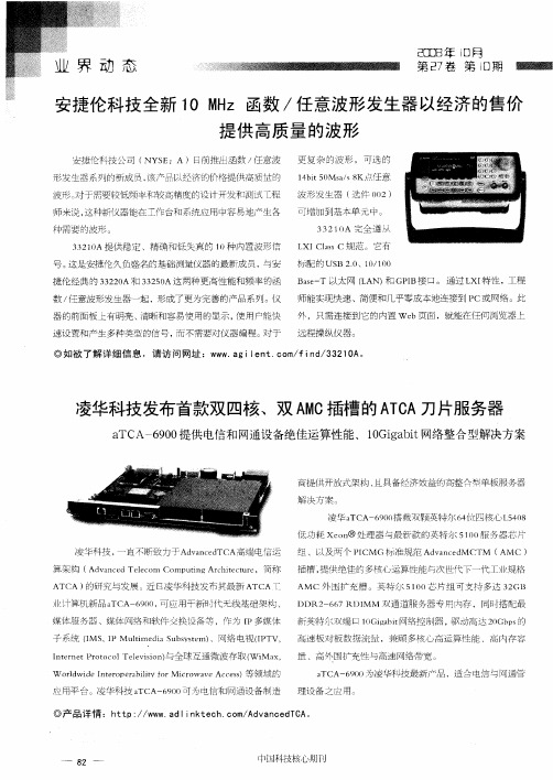
刀片之争——四款刀片服务器测评作者:清水编译来源:《计算机世界》2010年第31期今年3月,英特尔32纳米的至强处理器5600系列正式推出,它主要用于双路服务器和工作站系统,可带来更加出色的计算性能及能效。
美国《InfoWorld》近期对基于该处理器的戴尔PowerEdge M1000e、惠普BladeSystem c7000和IBM BladeCenter H等数款刀片服务器系统进行了测试。
英特尔至强处理器5600系列(研发代号为Westmere-EP)是英特尔新一代智能服务器处理器,与上一年英特尔推出的至强5500系列相比,在技术上有了很大进步。
它采用更为先进的32纳米制程工艺,成为英特尔服务器和工作站处理器中首批采用该工艺且最多集成了六个内核的芯片产品。
另外,它采用英特尔第二代高K金属栅极晶体管技术,实现了处理器计算速度的提升和能耗降低,使至强5600 系列在性能上比基于45纳米的至强5500系列提升最高达60%。
基于这一性能表现,数据中心用户完全可以用1台基于至强5600系列的服务器来替换15台基于单核处理器的旧服务器,并最短在5个月内收回新服务器的采购成本。
在英特尔官方发布至强5600(Westmere)处理器之前,戴尔、惠普和IBM采用这款最新处理器的刀片服务器送到了《Infoworld》在夏威夷大学的测评中心。
之后进行的基准测试表明,Westmere把刀片推向了新的高度。
我们在测评中还添加了经济型的Supermicro刀片机箱。
带4块刀片的戴尔、惠普或IBM机箱起价都超过4万美元,而Supermicro解决方案的成本只是它们的零头,虽然它与这三大刀片系统不是一个级别的,但对可能不需要最新功能或最高性能的公司来说却是个值得关注的选择。
因此,我们也对它进行了同样的测试。
所有测试工作都在夏威夷大学的高级网络计算实验室(ANCL)进行。
测试介绍这次测试我们没有使用HPC基准测试,而是选择了一套定制的VMware测试和一系列实际性能指标的测试。
.华德安数据采集工作站简单使用手册.一、前言 (3)二、数据采集工作站的开、关机流程 (3)1、数据采集工作站的开机流程 (3)2、数据采集工作站的关机流程 (5)三、执法记录仪与数据采集工作站的数据导入 (6)四、数据采集工作站的数据查询 (9)五、数据管理 (10)1、后台访问数据采集工作站 (10)2、执法数据重命名及执法类型分类 (11)六、常见问题及解决方法 (13)一、前言华德安数据采集工作站是以嵌入式计算机技术为基础、软硬件定制开发的专用计算机系统。
执法记录仪接入数据采集工作站后,工作站对执法记录仪内的所有视音频、音频、图片及日志等数据进行自动采集。
数据采集完毕后执法记录仪已存储的数据将自动清空。
并可通过采集工作站触摸屏对已导入的数据进行查询,还通过网络访问数据采集工作站进行查询、浏览、下载和系统维护。
该数据采集工作站只能连接华德安所生产的单警执法记录仪,请勿连接其他厂家执法记录仪。
二、数据采集工作站的开、关机流程1、数据采集工作站的开机流程第一步:电源线接数据采集工作站电源接口(接AC 220V~50Hz),RJ-45网线插入网线接口(注:网线接口插入后,请确认工作站已正确连接到重庆海事局内网)。
如下图第二步:将电源开关开启到“I”档,此时电源指示灯点亮为红色。
如下图第三步:按下主机开关(注:按下后即松开,请勿一直按着),数据采集工作站开始启动,并伴有“Windows”操作系统启动音乐,显示屏将会显示工作界面,表示数据采集工作站已正常启动。
如下图2、数据采集工作站的关机流程第一步:点击数据采集工作站触摸屏工作界面右上角的“关于”按钮,将弹出一对话框,再点击“复位”按钮后,数据采集工作站工作界面将退出,此时触摸屏显示为“Windows”操作系统桌面。
三秒钟后工作界面将自动重启。
可利用这三秒钟的间隙时间点击系统桌面左下角的“开始”,进行电脑操作系统正常关机流程。
如下图第二步:待电脑操作系统正常关机完毕后,将电源开关开启到“O”档,三、执法记录仪与数据采集工作站的数据导入第一步:将执法记录仪的mini USB接口连接到数据采集工作站的数据线后,执法记录仪将自动开机并显示连接画面,表示执法记录仪已和数据采集工作站正确联机。
Data Sheet Fujitsu CELSIUS W580Fujitsu recommends Windows 10 Pro for business.Data SheetFujitsu CELSIUS W580Mini CAD PowerhouseIf you thought you would need to sacrifice performance, expandability, price or energy efficiency in a microtower design – think again. As an industry first, the FUJITSU CELSIUS W580 desktop workstation goes far and beyond with its innovative 21-liter, space-saving microtower design.No compromise in terms of performance, expandability and priceDesigned with CAD customers in mind: performance, reliability and great flexibility - at an affordable priceChoose between the energy-efficient Intel® Core™ processors or the powerful Intel® Xeon® E-2200 processor familySupport of Windows 10 Pro64 GB DDR4 2,666 MHz memory (incl. ECC) Maximum capacity of 16 TBBoost your storage performance with super-fast PCIe SSDsIndustry’s smallest VR-ready desktop workstation Innovative space-saving design - made in EuropeAn industry first: 21-liter desktop microtower workstationNVIDIA® Quadro® RTX 4000 VR-ready graphics (with CELSIUS W580power) Optimized thermal management and cooling solutionsEnjoy a silent workplace environment, thanks to low noise emission down to 18 dB(A) (depending on configuration)Multi-monitor experienceIdeal for showrooms, control rooms, surveillance or financial services companies Up to 8 monitors with the NVIDIA® Mosaic™ technology2-in-1: Workstation and Point-of-Sales deviceYour workstation can be deployed as a traditional workstation as well as a point-of-sales device in any retail environmentConnect your cash drawer and your scanner to two serial portsSupport of 24/7 operation with reliable high-endurance and business critical drivesComponentsProcessor Intel® Xeon® processor E-2288G (8 Cores / 16 Threads, 3.70 GHz, up to 5.0 GHz, 16 MB)Intel® Xeon® processor E-2286G (6 Cores / 12 Threads, 4.00 GHz, up to 4.9 GHz, 12 MB)Intel® Xeon® processor E-2278G (8 Cores / 16 Threads, 3.40 GHz, up to 5.0 GHz, 16 MB)Intel® Xeon® processor E-2276G (6 Cores / 12 Threads, 3.80 GHz, up to 4.9 GHz, 12 MB)Intel® Xeon® processor E-2274G (4 Cores / 8 Threads, 4.00 GHz, up to 4.9 GHz, 8 MB)Intel® Xeon® processor E-2246G (6 Cores / 8 Threads, 3.60 GHz, up to 4.8 GHz, 12 MB)Intel® Xeon® processor E-2244G (4 Cores / 8 Threads, 3.80 GHz, up to 4.8 GHz, 8 MB)Intel® Xeon® processor E-2236 (6 Cores / 12 Threads, 3.40 GHz, up to 4.8 GHz, 12 MB)Intel® Xeon® processor E-2234 (4 Cores / 8 Threads, 3.60 GHz, up to 4.8 GHz, 8 MB)Intel® Xeon® processor E-2226G (6 Cores / 6 Threads, 3.40 GHz, up to 4.6 GHz, 12 MB)Intel® Xeon® processor E-2224G (4 Cores / 4 Threads, 3.50 GHz, up to 4.7 GHz, 8 MB)Intel® Xeon® processor E-2224 (4 Cores / 4 Threads, 3.40 GHz, up to 4.6 GHz, 8 MB)Intel® Xeon® processor E-2186G (6 Cores / 12 Threads, 3.80 GHz, up to 4.7 GHz, 12 MB, Intel® UHD Graphics P630) *Intel® Xeon® processor E-2174G (4 Cores / 8 Threads, 3.80 GHz, up to 4.7 GHz, 8 MB, Intel® UHD Graphics P630) *Intel® Xeon® processor E-2136 (6 Cores / 12 Threads, 3.30 GHz, up to 4.5 GHz, 12 MB) *Intel® Xeon® processor E-2134 (4 Cores / 8 Threads, 3.50 GHz, up to 4.5 GHz, 8 MB) *Intel® Xeon® processor E-2126G (6 Cores / 6 Threads, 3.30 GHz, up to 4.5 GHz, 12 MB, Intel® UHD Graphics P630) *Intel® Xeon® processor E-2124 (4 Cores / 8 Threads, 3.30 GHz, up to 4.5 GHz, 8 MB) *Intel® Core™ i9-9900 processor (8 Cores / 16 Threads, 3.10 GHz, up to 5.0 GHz, 16 GB, Intel® UHD Graphics 630)Intel® Core™ i9-9900K processor (8 Cores / 16 Threads, 3.60 GHz, up to 5.0 GHz, 16 GB, Intel® UHD Graphics 630)Intel® Core™ i7-9700 processor (8 Cores / 8 Threads, 3.00 GHz, up to 4.7 GHz, 12 MB, Intel® HD Graphics 630) *Intel® Core™ i7-9700K processor (8 Cores / 8 Threads, 3.60 GHz, up to 4.9 GHz, 12 MB, Intel® UHD Graphics 630) *Intel® Core™ i5-9600 processor (6 Cores / 6 Threads, 3.10 GHz, up to 4.6 GHz, 9 MB, Intel® UHD Graphics 630) *Intel® Core™ i5-9500 processor (6 Cores / 6 Threads, 3.00 GHz, up to 4.4 GHz, 9 MB, Intel® UHD Graphics 630) *Intel® Core™ i5-8600 processor (6 Cores / 6 Threads, 3.10 GHz, up to 4.3 GHz, 9 MB, Intel® UHD Graphics 630) *Intel® Core™ i3-9100 processor (4 Cores / 4 Threads, 3.60 GHz, up to 4.2 GHz, 6 MB, Intel® HD Graphics 630) *Intel® vPro® Platform with all Intel® Xeon® processorsNo Intel® vPro® technology with Intel® Core™ i5 and Core™ i7 processors*with Intel® Turbo Boost Technology 2.0 (clock speed and performance will vary depending on workload and othervariables)Operating system preinstalledOperating system pre-installed Windows 10 Pro for WorkstationsWindows 10 Pro. Fujitsu recommends Windows 10 Pro forbusiness.Windows 10 Home Windows 10 Pro for WorkstationsWindows 10 Pro. Fujitsu recommends Windows 10 Pro for business.Windows 10 HomeOperating system compatible Linux LinuxOperating system notes Certified for Red Hat© Enterprise LinuxCertified for SUSE Enterprise DesktopCertified for SUSE Enterprise ServerFor some configurations third party drivers are currentlynot available or configuration restrictions may apply.Windows 10 Support: After the end of the product lifeFUJITSU will continue to test and support all upcomingWindow 10 releases for a period of maximum 5 years –depending on the available extension of hardware servicesthrough FUJITSU Warranty top ups. For details please see“FUJITSU Service Statement for Windows 10 Semi-Annual-Channel Support” at .Certified for Red Hat© Enterprise LinuxCertified for SUSE Enterprise Desktop (pending) Certified for SUSE Enterprise Server (pending)For some configurations third party drivers are currently not available or configuration restrictions may apply. Windows 10 Support: After the end of the product life FUJITSU will continue to test and support all upcoming Window 10 releases for a period of maximum 5 years – depending on the available extension of hardware services through FUJITSU Warranty top ups. For details please see “FUJITSU Service Statement for Windows 10 Semi-Annual-Channel Support” at .Memory modules 4 GB (1 module(s) 4 GB) DDR4, unbuffered, non-ECC, 2,666 MT/s, UDIMM8 GB (1 module(s) 8 GB) DDR4, unbuffered, ECC, 2,666 MT/s, UDIMM8 GB (1 module(s) 8 GB) DDR4, unbuffered, non-ECC, 2,666 MT/s, UDIMM16 GB (1 module(s) 16 GB) DDR4, unbuffered, ECC, 2,666 MT/s, UDIMM16 GB (1 module(s) 16 GB) DDR4, unbuffered, non-ECC, 2,666 MT/s, UDIMMGraphics High-end 3D: NVIDIA® Quadro® RTX 4000, 8 GB, PCIe x16, 3 x DisplayPort, 1 x Virtual LinkMidrange 3D: NVIDIA® Quadro® P2200, 5 GB, PCIe x16, 4 x DisplayPortMidrange 3D: AMD Radeon™ Pro WX 5100, 8 GB, 320 stream processors, PCIe x16, 4 x DisplayPortEntry 3D: NVIDIA® Quadro® P1000, 4 GB, PCIe x16, 4 x miniDPEntry 3D: AMD Radeon™ Pro WX 3100, 4 GB, 320 stream processors, PCIe x16, 1 x DisplayPort, 2 x miniDPEntry 3D: AMD Radeon™ Pro WX 2100, 2 GB, 320 stream processors, PCIe x16, 1 x DisplayPort, 2 x miniDPEntry 3D: NVIDIA® Quadro® P620, 2 GB, PCIe x16, 4 x miniDPEntry 3D: NVIDIA® Quadro® P400 , 2 GB, PCIe x16, 3 x miniDPRemote Graphics: CELSIUS RemoteAccess Dual Card, PCIe x1, 2 x miniDP, PCoIPRemote Graphics: CELSIUS RemoteAccess Quad Card, PCIe x1, 4 x miniDP, PCoIPOthers: VGA Extension CardOthers: DP to DVI-D (single link) Adapter CableOthers: MiniDP to DP Adapter CableNotes NVIDIA® Quadro® P4000 requires CELSIUS W580power or CELSIUS W580power+.Hard disk drives (internal)SSD SATA III, 960 GB High Endurance, 1DWDP, 2.5-inchSSD SATA III, 480 GB High Endurance, 1DWDP, 2.5-inchSSD SATA III, 240 GB High Endurance, 1DWDP, 2.5-inchSSD PCIe, 2048 GB M.2 NVMe Highend moduleSSD PCIe, 1024 GB M.2 NVMe Highend moduleSSD PCIe, 512 GB M.2 NVMe Highend moduleSSD PCIe, 256 GB M.2 NVMe Highend moduleSSD PCIe, 1x 2048 GB M.2 NVMe Highend cardSSD PCIe, 1x1024 GB M.2 NVMe Highend cardSSD PCIe, 1x 512 GB M.2 NVMe Highend cardSSD PCIe, 1x 256 GB M.2 NVMe Highend cardRAID1 Bundle 2x512GB M.2 NVMe HighendRAID1 Bundle 2x256GB M.2 NVMe HighendSSD PCIe, 1024 GB M.2 NVMe moduleSSD PCIe, 512 GB M.2 NVMe moduleSSD PCIe, 256 GB M.2 NVMe moduleSSD PCIe, 1024 GB M.2 NVMe module, SEDSSD PCIe, 512 GB M.2 NVMe module, SEDSSD PCIe, 256 GB M.2 NVMe module, SEDSSD PCIe, 1x 1024 GB M.2 NVMe cardSSD PCIe, 1x 512 GB M.2 NVMe cardSSD PCIe, 1x 256 GB M.2 NVMe cardSSD SATA III, 1024 GB, 2.5-inchSSD SATA III, 512 GB, 2.5-inchSSD SATA III, 256 GB, 2.5-inchSSD SATA III, 128 GB, 2.5-inchHDD SATA III, 7,200 rpm, 4,000 GB, 3.5-inch, business criticalHDD SATA III, 7,200 rpm, 2,000 GB, 3.5-inch, business criticalHDD SATA III, 7,200 rpm, 1,000 GB, 3.5-inch, business criticalHDD SATA III, 7,200 rpm, 2,000 GB, 2.5-inch, business criticalHDD SATA III, 7,200 rpm, 1,000 GB, 2.5-inch, business criticalHDD SATA III, 7,200 rpm, 2,000 GB, 3.5-inchHDD SATA III, 7,200 rpm, 1,000 GB, 3.5-inchHard disk notes One Gigabyte equals one billion bytes, when referring to hard disk drive capacity.24/7 ready (business critical HDDs required)Up to 20 GB of HDD space is reserved for system recoverySSHD (Solid State Hard Disk, Hybrid drive)SED (Self-Encrypting Drive)SSD (Solid State Disk)Drives (optional)BD Triple Writer SATA ultra slim (tray)DVD-ROMDVD Super MultiDVD Super Multi ultra slim (tray)MultiCard Reader 24in1 USB 2.0 3.5”Base unitBase unit CELSIUS W580CELSIUS W580powerMainboardMainboard type D3617Chipset Intel® C246Processor socket LGA 1151Processor quantity maximum1Supported capacity RAM (max.)64 GBMemory slots 4 DIMM (DDR4) ECC/non-ECCMemory frequency2,666 MT/sMemory notes Dual channel supportFor dual channel performance, 2 memory modules have to be ordered. Capacity per channel has to be the same.2666 MHz may be clocked down to 2400 MHz depending on processor and memory configurationLAN10/100/1,000 MBit/s Intel® I219LMBIOS version AMI Aptio VUEFI Specification 2.6BIOS features BIOS Flash EPROM update by softwareRecovery BIOSUnified Extensible Firmware Interface (UEFI)Audio type On boardAudio codec Realtek ALC671Audio features Internal speaker supports audio playback (optional), High Definition audio, 5.1 surround soundI/O controller on boardSerial ATA total8thereof SATA III8thereof eSATA 2 (optional)Controller functions Serial ATA III (6 Gbit)NCQAHCIRAID 0/1/5/10S26361-K1446-V515 CELSIUS W580Audio: line-in1Audio: line-out1Front audio: microphone1Front audio: headphone1Internal speakers1USB 2.0 total5USB 3.1 Gen1 (USB 3.0) total3S26361-K1446-V515 CELSIUS W580USB 3.1 Gen2 total5USB front2x USB 2.0; 2x USB 3.1 (gen2), 1x USB 3.1 (gen2) Type C; optional: 1x USB 3.1 Type-C (Gen2) via add on card and frontadapter bayUSB rear2x USB 2.0; 3x USB 3.1 (Gen1); 1x USB 3.1 (Gen2); optional: additional 1x USB 3.1 Type C (Gen2) via add on card USB internal1x USB 2.0 + 1x USB A 3.1 (Gen2)VGA optional: via adapter cardDisplayPort2DVI 1 (DVI-D)Serial (RS-232) optional: serial port (9pin, 16 byte FIFO, 16550 compatible)Mouse / Keyboard (PS/2)2Ethernet (RJ-45)1Parallel 1 (optional) (25pin with EPP and ECP)eSATA 1 (optional)Interface Module notes Anytime USB charge functionality, USB Typ C connector supports up to 15WInput device / componentsInput devices (optional)KeyboardMouseKBPC PX ECOMouse M440 ECOSpace Explorer USBDrive bays total62.5-inch internal bays13.5-inch internal bays23.5-inch external bays15.25-inch external bays2Drive bay notes5,25” bays: one bay in HH format, one bay for slim optical disc drive only;internal 3.5” bays: 3.5” drive (screwless) or 2.5” drive (screws);M.2-2280 1 x on mainboard (for PCIe or SATA SSD modules), supports Intel® Optane™ technologySlotsPCI-Express 3.0 x1 2 x ( / ) Full heightPCI-Express 3.0 x4 (mech. x16) 1 x (215 mm / ) Full heightPCI-Express 3.0 x16 1 x (240 mm / ) Full heightGraphics brand name Intel® HD Graphics P630, Intel® HD Graphics 630Shared video memory up to 1,782 MBTFT resolution (VGA)1,024 x 768 pixel1,280 x 1,024 pixel1,360 x 768 pixel1,440 x 900 pixel1,600 x 900 pixel1,600 x 1,200 pixel1,680 x 1,050 pixel1,920 x 1,080 pixelTFT resolution (DVI)1,280 x 1,024 pixel1,360 x 768 pixel1,440 x 900 pixel1,600 x 900 pixel1,680 x 1,050 pixel1,920 x 1,080 pixel1,920 x 1,200 pixelTFT resolution (DisplayPort)1,280 x 1,024 pixel1,360 x 768 pixel1,440 x 900 pixel1,600 x 900 pixel1,680 x 1,050 pixel1,920 x 1,080 pixel1,920 x 1,200 pixel2,560 x 1,440 pixel2,560 x 1,600 pixel3,440 x 1,440 pixel3,840 x 2,160 pixel4,096 x 2,304 pixelGraphics features Support for up to three independent displaysDirectX® 12HDCP supportOpenCL® 2.0OpenGL® 4.4One DisplayPort connector can be converted to DVI-D or HDMI with an optional external adapterFor multi monitoring mode, graphics card and integrated graphics run in parallelDisplayPort interface supports Ver. 1.2 incl. Multi-StreamDVI-D interface supports audio output for HDMI monitorsGraphics notes up to 1 GB dedicated video memory (main memory owned and locked for graphics use)Tested resolutions, depending on display type additional resolutions and frequencies possibleShared memory depending on main memory size and operating systemResolution (color depth up to 32 Bit/pixel)For TFT we recommend using 60HzElectrical valuesPower efficiency note power supply efficiency (at 230V; 10% / 20% / 50% / 100%load) : 75% / 83% / 85% / 84%power supply efficiency at 10% / 20% / 50% / 100% load for 230V: 80% / 87% / 90% / 87%; for 115V: 80% / 87% / 90% / 87%Rated voltage range100 V - 240 V100 V - 240 V Rated frequency range50 Hz - 60 Hz50 Hz - 60 Hz Operating voltage range90 V - 264 V90 V - 264 V Operating line frequency range47 Hz - 63 Hz47 Hz - 63 Hz Max. output of single power supply280 W400 W Power factor correction/active power active activeDimension with stand (W x D x H)Dimensions (W x D x H)180 x 304 x 375 mm7.09 x 11.97 x 14.76 inchOperating position VerticalWeight approx. 10 kg approx. 12 kg Weight (lbs)approx. 30.86 lbsWeight notes Actual weight may vary depending on configurationOperating ambient temperature10 - 35 °C (50 - 95 °F)Operating relative humidity 5 - 85 % (relative humidity)Product CELSIUS W580Model MI6WGermany GS (planned)Europe CEUSA/Canada FCC Class BcTUVusGlobal RoHS (Restriction of hazardous substances)WEEE (Waste electrical and electronic equipment)Microsoft Operating Systems (HCT / HCL entry / WHQL)ENERGY STAR® in progressChina CCC (planned)CCC (depending on configuration)CEL (Chinese energy label)TPM 2.0 for China (optional)Compliance link https:///sites/certificatesAdditional SoftwareAdditional software (preinstalled)Adobe® Reader® (pdf reader)McAfee® LiveSafe™ (provides award-winning antivirus protection for your PC and much more. 30 days trial pre-installed)Microsoft Office (1 month trial for new Microsoft® Office 365 customers. Buy Microsoft Office.)Additional software (optional)Recovery DVD for Windows®Drivers & Utilities DVD (DUDVD)CyberLink PowerDVD BD (playback software for Blu-ray Disc™)CyberLink PowerDVD DVD (playback software for DVD)Nero Essentials XLMicrosoft® Office Professional 2019Microsoft® Office Home and Business 2019(A Microsoft Account is required to activate each copy of these products. For purchase and activation only in the regionin which it was acquired.)SecurityPhysical Security Kensington Lock supportEye for padlockIntegrated cabinet lock (optional)Cable Cover (optional; covers and secures the ports andcables on rear side)Kensington Lock supportEye for padlockIntegrated cabinet lock (optional)Cable Cover (optional; covers and secures the ports and cables on rear side)System and BIOS Security Embedded security (TPM 2.0)EraseDisk (optional)Credential Guard Ready and Device Guard Capable(Windows 10, v. 1809; requires 8 GB or more system RAMand SSD PCIe NVME)Boot sector virus protectionWrite protect option for the Flash EPROMControl of all USB interfacesExternal USB ports can be disabled separatelyControl of external interfaces Embedded security (TPM 2.0)EraseDisk (optional)Credential Guard Ready and Device Guard Capable (Windows 10, v. 1809; requires 8 GB or more system RAM and SSD PCIe NVME)Boot sector virus protectionWrite protect option for the Flash EPROMControl of all USB interfacesExternal USB ports can be disabled separatelyControl of external interfacesUser Security User and supervisor BIOS passwordHard disk passwordAccess protection via external SmartCard reader (optional)Access protection via internal SmartCard reader (optional)Workplace Protect (secure authentication solution)User and supervisor BIOS passwordHard disk passwordAccess protection via external SmartCard reader (optional) Access protection via internal SmartCard reader (optional) Workplace Protect (secure authentication solution)Workplace Embedded Tools Auto BIOS Update via Fujitsu ServerAuto BIOS Update via customer serverEasy PC Protection Auto BIOS Update via Fujitsu Server Auto BIOS Update via customer server Easy PC ProtectionManageability MiscellaneousKeyboard on (Special Fujitsu keyboard required) Keyboard on with one key (KBPX Eco, KB521) Keyboard on with 2 keys (CTRL+CTRL) with PS2 or special USB keyboardsKeyboard on with any key (USB)Thermal managementExtended lifetime 24/7 (limited configurations)Keyboard on (Special Fujitsu keyboard required) Thermal managementKeyboard on with one key (KBPX Eco, KB521) Keyboard on with 2 keys (CTRL+CTRL) with PS2 or special USB keyboardsKeyboard on with any key (USB)Extended lifetime 24/7 (limited configurations)WarrantyWarranty period 3 years (depending on country)Warranty type Bring-In / Onsite Service (for countries within region EMEIA, for all other countries depending on local regulations) Product Support Services - the perfect extensionRecommended Service9x5, Onsite Response Time: Next Business DaySpare Parts availability 5 years after end of product lifeRecommended AccessoriesDisplay P27-8 TS UHDThe FUJITSU Display P27-8 TS UHD is perfect for multi-monitor usescenarios with its 3840 x 2160 Ultra HD resolution and the thin bezelhousing. The monitor has a 78°/178° wide viewing angle and a 100% sRGB color space to deliver you a consistent high picture quality. Features like ECO function, the DisplayView™ IT Suite manageability software as a range of connectivity options meet the requirements of medium- and large-sized businesses.Order Code: S26361-K1610-V160ContactFujitsu Technology SolutionsAddress: x-xx-x, street, city, state, ZIP code, country Phone: xx-xxxx-xxxx Fax : xx-xxxx-xxxxEmail:********************.com Website: /[country]2021-09-06 CE-ENdelivery subject to availability. Any liability that the data and illustrations are complete, actual or correct is excluded. Designations may be trademarks and/or copyrights of the respective manufacturer, the use of which by third parties for their own purposes may infringe the rights of such ownerMore informationAll rights reserved, including intellectual property rights. Changes to technical data reserved. Delivery subject to availability. Any liability that the data and illustrations are complete, actual or correct is excluded.Designations may be trademarks and/or copyrights of the respective manufacturer, the use of which by third parties for their own purposes may infringe the rights of such owner.For further information see /terms_of_use.html Copyright © Fujitsu Technology Solutions。
Technique CommandUse this command to select an electrochemical technique.This command presents an Electrochemical Techniques dialog box:The following options allow you to select an electrochemical technique: Technique SelectionSelect the electrochemical technique you want to use. This box lists the techniques available in the instrument. Double clicking the technique you want to select is equivalent to selecting the technique and clicking the OK button. Polarographic ModeCheck this box will enable the polarographic mode. In the polarographic mode, the mercury drop will be allowed to grow and be dislodged for every data point.Only a few techniques are allowed to have polarographic mode: Sampling Current (Staircase) Polarography (SCP), Differential Pulse Polarography (DPP), NormalPulse Polarography (NPP), Differential Normal Pulse Polarography (DNPP), A.C. Polarography (ACP), and Second Harmonic A.C. Polarography (SHACP).Once polarographic mode is enabled, stripping mode is disabled. In order to set stripping mode by using the Stripping Mode command in Control Menu, you have to uncheck the polarographic mode.This command has a toolbar button:Parameters CommandUse this command to set experimental parameters.This command presents a Parameter dialog box so you can select the parameters you want to use.Depending on the technique, the parameters dialog box will be different. The followings are the parameters for different techniques:Parameters for Cyclic VoltammetryParameters for Linear Sweep VoltammetryParameters for Sampled Current VoltammetryParameters for Tafel PlotParameters for ChronoamperometryParameters for ChronocoulometryParameters for Differential Pulse VoltammetryParameters for Normal Pulse VoltammetryParameters for Differential Normal Pulse VoltammetryParameters for Square Wave VoltammetryParameters for A.C. VoltammetryParameters for 2nd Harmonic A.C. VoltammetryParameters for Amperometric i-t CurveParameters for Differential Pulse AmperometryParameters for Double Differential Pulse AmperometryParameters for Triple Pulse AmperometryParameters for Integrated Pulse Amperometric DetectionParameters for Bulk Electrolysis with CoulomteryParameters for Hydrodynamic Modulation VoltammetryParameters for Sweep-Step FunctionsParameters for Multi-Potential StepsParameters for A.C. ImpedanceParameters for Impedance - TimeParameters for Impedance - PotentialParameters for ChronopotentiometryParameters for Chronopotentiometry with Current RampParameters for Multi-Current StepsParameters for Potentiometric Stripping AnalysisParameters for Open Circuit Potential - TimeFor details of the parameters of each technique, see the description of individual dialog box of related techniques.This command has a toolbar button:Parameters for Cyclic VoltammetryIn Cyclic Voltammetry (CV), potential is scanned from Init E toward either High E or Low E depending on the Init P/N. The potential will then scan back. The following diagram shows the potential waveform applied as the function of time. The current is recorded as the function of potential.The following are the experimental parameters, their range and descriptions:Parameters RangeDescription Init E (V)-10 - +10Initial potentialHigh E (V)-10 - +10High limit of potential scan Low E (V)-10 - +10Low limit of potential scan Init P/NPositive or Negative Initial scan direction Scan Rate (V/s)1e-6 - 20000Potential scan rateSweep Segments 1 - 1000000Sweep segments, each segments is half cycle Sample Interval (V)1e-6 - 0.064Data sampling intervalQuiet Time (sec)0 - 100000Quiescent time before potential scan Sensitivity (A/V)1e-12 - 0.1Sensitivity scaleAuto SensCheck or Uncheck Automatic sensitivity switching during run Scan Complete Cycles Check or Uncheck Scan complete cyclesAuxiliary Signal RecordingCheck or UncheckSimultaneously external signal recording when the scan rate is less than 0.25V/sP o t e n t i a l (V )Init ETime (s)High EScan Rate (V/s)Segment 1Segment 2Segment 3Low ENotes:1.High E and Low E should be at least 0.01 V apart.2.If unreasonable High E and Low E are entered, the system will automatically readjust them.3.Depending on the Init E, High E and Low E value, the system will automatically readjust initial scan direction.4.The maximum potential scan range is 13.1V.5.The potential increment is 0.1 mV if the scan rate is below 500 V/s. The potential increment is 1 mV at the scan rate of 5000 V/s, and 4 mV at 20000 V/s.6.The sample interval can be 1 mV When the scan rate is below 1000 V/s. The sample interval is 2 mV at the scan rate of 2000 V/s, 5 mV at 5000 V/s, and 20 mV at 20000 V/s. If the scan rate is high, the data sampling interval will be automatically increased.7.When large number of sweep segments are involved, the data sampling interval will be automatically increased up to 0.02V. If the scan rate is higher than 0.5V/s, the number of sweep segments will be limited by the memory size (64000 points). If the scan rate is below 0.5V/s, the maximum data length set by the System command will take effect. When the scan rate is low, the specified sweep segments will be executed, but only limited number of segments will be stored. Large sweep segments might be useful for conditioning of electrodes.8.When scan rate is below 0.01 V/s, the sensitivity scale during run can be automatically switched according to the current level. When it is activated, the sensitivity selection will have no effect on the measurement. However, the automatic sensitivity switching range will be from 1e-8 - 0.1 A/V, instead of 1e-12 - 0.1 A/V. The Picoamp Booster will not work either. In order to select higher sensitivities, automatic sensitivity switching option needs to be disabled.9.Scan Complete Cycles will only work for Sweep Segments at 3, 5, 7, 9, (odd numbers) and if Initial E is different from High E and Low E. When it works, the last segment will stop at Initial E instead of High E or Low E.10.If the scan rate is lower than 0.25V/s, it is possible to record external voltage signal (such s spectroscopic signal) simultaneously with the voltammogram. Use the 9-pin D-connector on the real panel for signal input. Check the User's Manual for the pin-out and signal level requirements.Parameters for Linear Sweep VoltammetryIn Linear Sweep Voltammetry (LSV), potential is scanned from Init E toward Final E. The following diagram shows the potential waveform applied as the function of time. The current is recorded as the function of potential.The following are the experimental parameters, their range and descriptions:Parameters RangeDescription Init E (V)-10 - +10Initial potential Final E (V)-10 - +10Final potential Scan Rate (V/s)1e-6 - 20000Potential scan rate Sample Interval (V)1e-6 - 0.064Data sampling intervalQuiet Time (sec)0 - 100000Quiescent time before potential scan Sensitivity (A/V)1e-12 - 0.1Sensitivity scaleAuto Sens Check or Uncheck Automatic sensitivity switching during runAuxiliary Signal RecordingCheck or UncheckSimultaneously external signal recording when the scan rate is less than 0. 25V/sNotes:1.Init E and Final E should be at least 0.01 V apart.2.The maximum potential scan range is 13.1 V.P o t e n t i a l (V )Init ETime (s)Final EScan Rate (V/s)3.When the scan rate is high, the data sampling interval will be automatically increased.4.The potential increment is 0.1 mV if the scan rate is below 500 V/s. The potential increment is 1 mV at the scan rate of 5000 V/s, and 4 mV at 20000 V/s.5.The sample interval can be 1 mV When the scan rate is below 1000 V/s. The sample interval is 2 mV at the scan rate of 2000 V/s, 5 mV at 5000 V/s, and 20 mV at 20000 V/s. If the scan rate is high, the data sampling interval will be automatically increased.6.When scan rate is below 0.01 V/s, the sensitivity scale during run can be automatically switched according to the current level. When it is activated, the sensitivity selection will have no effect on the measurement. However, the automatic sensitivity switching range will be from 1e-8 - 0.1 A/V, instead of 1e-12 - 0.1 A/V. The Picoamp Booster will not work either. In order to select higher sensitivities, automatic sensitivity switching option needs to be disabled.7.If the scan rate is lower than 0.25V/s, it is possible to record external voltage signal (such s spectroscopic signal) simultaneously with the voltammogram. Use the 9-pin D-connector on the real panel for signal input. Check the User's Manual for the pin-out and signal level requirements.8. Linear polarization resistance plot can be obtained by the Special Plots command under the Graphics menu.Parameters for Staircase VoltammetryIn Staircase Voltammetry (SCV), potential is increment from Init E toward Final E. The potential may be scanned back. The following diagram shows the potential waveform applied as the function of time. The current is sampled at every potential increment and recorded as the function of potential.The following are the experimental parameters, their range and descriptions:Parameters RangeDescription Init E (V)-10 - +10Initial potential Final E (V)-10 - +10Final potentialIncr E (V)1e-3 - 0.05Increment potential of each stepSegments1 - 10000Number of scan segmentsSampling Width (sec)1e-4 - 50Data sampling width for each point Step Period (sec)0.001 - 50Potential step period or dropping time Quiet Time (sec)0 - 100000Quiescent time before potential scan Sensitivity (A/V)1e-12 - 0.1Sensitivity scaleNotes:1.Init E and Final E should be at least 0.01 V apart.2.Sampling Width should be no more than half of Step Period, otherwise the system will automatically readjust Sampling Width.3.Data sampling always occurs at the end of each step.P o t e n t i a l (V )Init ETime (s)Final E Segment 1Segment 2Incr ESample Width Step PeriodParameters for Tafel PlotIn Tafel Plot (TAFEL), potential is scanned from Init E toward Final E. The potential may be scanned back. The following diagram shows the potential waveform applied as the function of time. The logarithm of current is recorded as the function of potential.The following are the experimental parameters, their range and descriptions:Parameters RangeDescription Init E (V)-10 - +10Initial potential Final E (V)-10 - +10Final potentialSweep Segments1 - 2Sweep segments, each segments is half cycle Hold Time at Final E (s)0 - 100000Potential hold time atfer 1st sweep segent Scan Rate (V/s)1e-6 - 0.1Potential scan rateQuiet Time (sec)0 - 100000Quiescent time before potential scan Sensitivity (A/V)1e-12 - 0.1Sensitivity scaleAuto SensCheck or UncheckAutomatic sensitivity switching during runNotes:1.Init E and Final E should be at least 0.01 V apart.2.Corrosion rate calculation can be obtained by Special Analysis command under the Analysis menu.P o t e n t i a l (V )Init ETime (s)Final EScan Rate (V/s)Segment 1Segment 2Hold TimeParameters for ChronoamperometryIn Chronoamperometry (CA), potential is stepped from Init E toward either High E or Low E depending on the Init P/N. The potential will then step back. The following diagram shows the potential waveform applied as the function of time. The current is recorded as the function of time.The following are the experimental parameters, their range and descriptions:ParametersRangeDescription Init E (V)-10 - +10Initial potentialHigh E (V)-10 - +10High limit of potential scan Low E (V)-10 - +10Low limit of potential scan Init P/NPositive or Negative Initial step directionNumber of Steps 1 - 320Number of potential steps Pulse Width (sec)1e-4 - 1000Potential pulse width Sample Interval (s)1e-6 - 10Sampling IntervalQuiet Time (sec)0 - 100000Quiescent time before potential step Sensitivity (A/V)1e-12 - 0.1Sensitivity scaleAuxiliary Signal RecordingCheck or UncheckSimultaneously external signalrecording when the sample interval is greater than 0.005 sP o t e n t i a l (V )Init ETime (s)High E Step 1Step 2Step 3Low EHigh EPulse WidthPulse WidthNotes:1.High E and Low E should be at least 0.01 V apart.2.If unreasonable High E and Low E are entered, the system will automatically readjust them.3.Depending on the Init E, High E and Low E value, the system will automatically readjust initial step direction.4.The maximum potential step range is 13.1 V.5.Shorter sample interval will increase data density, but will reduce the signal-noise ratio. If earlier transient data is important, shorter sample interval is recommended. If the later part of data is of interest, longer sample interval is recommended. However, minimum 100 points per step are required.6.If the sample interval is less than 0.002s, the data will not be transferred on the real-time base. Instead the data will be transferred after the experiment is completed. Cell is turned off during the data transfer unless the Cell On between Run option is selected. From start of experiment and data transfer there is a delay. The total number of data points will be limited to 64K due to internal memory size limitation. Sample interval might be automatically altered to adjust the data points in the reasonable range.7.If the sample interval is longer than 0.002s, data will be transferred during experiment. Maximum 64K total data points are allowed for each step. Sample interval might be automatically altered to adjust the data points in the reasonable range.8.If the sample interval is greater than 0.005s, it is possible to record external voltage signal (such s spectroscopic signal) simultaneously with the current. Use the 9-pin D-connector on the real panel for signal input. Check the Appendix of the User's Manual for the pin out.Parameters for ChronocoulometryIn Chronocoulometry (CC), potential is stepped from Init E toward Fianl E. The potential may step back. The following diagram shows the potential waveform applied as the function of time. The charge passing through the working electrode is recorded as the function of time.The following are the experimental parameters, their range and descriptions:Parameters RangeDescription Init E (V)-10 - +10Initial potential Final E (V)-10 - +10Final potentialNumber of Steps 1 - 320Number of potential steps Pulse Width (sec)1e-4 - 1000Potential pulse width Sample Interval (s)1e-6 - 10Sampling IntervalQuiet Time (sec)0 - 100000Quiescent time before potential step Sensitivity (C or A/V)1e-12 - 0.1or 1e-9C/V -1e-6 C/VSensitivity scaleNotes:1.Init E and Final E should be at least 0.01 V apart.2.The maximum potential step range is 13.1 V.P o t e n t i a l (V )Init ETime (s)Final E Step 1Step 2Step 3Init EFinal EPulse Width Pulse Width3. A true integrator (charge-to-voltage converter) can be chosen. In this case, the sensitivity is 1e-9C/V to 1e-6C/V. If the charge exceeds the 8e-6 coulomb, the capacitor of the integrator will be discharged and the new charge will be added to the previous value. This allows higher charge to be measured with the integrator. There might be discontinuity in charge-time curve due to the capacitor discharge. The discontinuity should be negligible. However, if it is significant to the measurement, you may choose to use the current-to-voltage converter and integrate the current measured by software.4.Current-to-voltage converter is not ideal for chronocoulometry, particularly if the early transient data is important, such as double layer capacitance, or surface reactions. Charge-to-voltage converter (true integrator) is a better choice.5. If current-to-voltage converter is selected due to high total charge, shorter sample interval will increase data density, but will reduce the signal-to-noise ratio. If earlier transient data is important, shorter sample interval is recommended. If the later part of data is of interest, longer sample interval is recommended. However, minimum 1000 points per step are required, unless sampling rate does not allow it.6.If the sample interval is less than 0.002s, the data will not be transferred on the real-time base. Instead the data will be transferred after the experiment is completed. Cell is turned off during the data transfer unless the Cell On between Run option is selected. From start of experiment and data transfer there is a delay. The total number of data points will be limited to 64K due to internal memory size limitation. Sample interval might be automatically altered to adjust the data points in the reasonable range.7.If the sample interval is longer than 0.002s, data will be transferred during experiment. Maximum 64K total data points are allowed for each step. Sample interval might be automatically altered to adjust the data points in the reasonable range.8.If the current-to-voltage converter is used, during the run, an “Overflow” warning might appear. This is due to the current transient immediately after the potential step. If the intercept (that gives information of double layer capacitance and adsorption) of Anson plot (Q-t1/2 plot) is not your primary interest, you may not worry about it. However, if the data distortion can be seen visually, you have to lower the sensitivity scale.Sometimes, you may use i/E converter filter to slow the system down, but make sure that the time constant of the filter (1/cutoff freq) is much shorter than the pulse width.In order to reduce noise and enhance the accuracy of the measurement, it is recommended to use the highest sensitivity scale possible.Parameters for Differential Pulse VoltammetryIn Differential Pulse Voltammetry (DPV), the base potential is incremented from Init E toward Final E. A potential pulse is applied. The current before the potential pulse and at the end of the potential pulse are sampled. The difference of these two current samples is recorded as the function of potential. The following diagram shows the potential waveform applied as the function of time and the current sampling scheme.The following are the experimental parameters, their range and descriptions:Parameters RangeDescription Init E (V)-10 - +10Initial potential Final E (V)-10 - +10Final potentialIncr E (V)±0.001 - ±0.05Increment potential of each point Amplitude (V)0.001 - 0.5Potential pulse amplitude Pulse Width (sec)0.001 - 10Potential pulse width Sampling Width (sec)1e-4 - 10Data sampling widthPulse Period (sec)0.01 - 50Potential pulse period or dropping time Quiet Time (sec)0 - 100000Quiescent time before potential scan Sensitivity (A/V)1e-12 - 0.1Sensitivity scaleNotes:1.Init E and Final E should be at least 0.01 V apart.2.Pulse Width should be no more than half of Pulse Period, otherwise the system will automatically readjust Pulse Width.3.Sampling Width should be no more than half of Pulse Width, otherwise the system will automatically readjust Sampling Width.4.When amplitude is negative, the pulse direction is different from the potential scan direction.P o t e n t i a l (V )Init ETime (s)Final EIncr ESample WidthPulse PeriodAmplitudePulse WidthParameters for Normal Pulse VoltammetryIn Normal Pulse Voltammetry (NPV), the base potential is held at Init E. A sequence of potential pulse with increasing amplitude is applied. The current at the end of the potential pulse is sampled. This current is recoded as the function of the pulsed potential. The following diagram shows the potential waveform applied as the function of time and the current sampling scheme.The following are the experimental parameters, their range and descriptions:Parameters RangeDescription Init E (V)-10 - +10Initial potential Final E (V)-10 - +10Final potentialIncr E (V)0.001 - 0.05Increment potential of each point Pulse Width (sec)0.001 - 10Potential pulse width Sampling Width (sec)1e-4 - 10Data sampling widthPulse Period (sec)0.01 - 50Potential pulse period or dropping time Quiet Time (sec)0 - 100000Quiescent time before potential scan Sensitivity (A/V)1e-12 - 0.1Sensitivity scaleNotes:1.Init E and Final E should be at least 0.01 V apart.2.Pulse Width should be no more than half of Pulse Period, otherwise the system will automatically readjust Pulse Width.3.Sampling Width should be no more than half of Pulse Width, otherwise the system will automatically readjust Sampling Width.P o t e n t i a l (V )Init ETime (s)Final EIncr ESample WidthPulse PeriodPulse WidthParameters for Differential Normal Pulse VoltammetryIn Differential Normal Pulse Voltammetry (DNPV), the base potential is held at Init E. A sequence of dual potential pulses are applied. The first pulse will increment its magnitude for each pulse. The second pulse has the constant amplitude. The current at the end of two potential pulses are sampled. The difference of these two current is recoded as the function of the first pulsed potential. The following diagram shows the potential waveform applied as the function of time and the current sampling scheme.The following are the experimental parameters, their range and descriptions:Parameters RangeDescription Init E (V)-10 - +10Initial potential Final E (V)-10 - +10Final potentialIncr E (V)0.001 - 0.05Increment potential of each point Amplitude (V)0.001 - 0.5Potential pulse amplitude 1st Pulse Width (sec)0.01 - 10First potential pulse width 2nd Pulse Width (sec)0.01 - 10Second potential pulse width Sampling Width (sec)0.001 - 5Data sampling widthPulse Period (sec)0.05 - 50Potential pulse period or dropping time Quiet Time (sec)0 - 100000Quiescent time before potential scan Sensitivity (A/V)1e-12 - 0.1Sensitivity scaleOpen Circuit at Initial ECheck or uncheckStep 1 could be either held at a constant potential or open circuitNotes:1.Init E and Final E should be at least 0.01 V apart.P o t e n t i a l (V )Init ETime (s)Final EIncr ESample WidthPulse Period Pulse Width Pulse WidthAmplitude2.In Differential Normal Pulse Voltammetry, the potential of first step is normally held at Initial E where no electrochemical reaction will occur. The second step is incremented every cycle. A current sample is taken at the later part of the period. The potential of the third is also incremented like the second step, but it is more positive (for positive scan) or more negative (for negative scan) than the second potential by a constant magnitude (amplitude). The second sample is taken at the later part of the period. The difference between the two current samples is reported as the function of the second potential.3.Pulse Width should be no more than half of Pulse Period, otherwise the system will automatically readjust Pulse Width.4.Sampling Width should be no more than half of Pulse Width, otherwise the system will automatically readjust Sampling Width.Parameters for Square Wave VoltammetryIn Square Wave Voltammetry (SWV), the base potential is increment from Init E towards Final E. A square wave potential is superimposed to the base potential. The base potential increments after each cycles of the square wave. The current at the end of forward and reverse steps are sampled. These two current are recoded as the function of the base potential. During the experiment, only the difference of two current samples is displayed. After experiment, the forward and reverse current are also available fordisplay. The following diagram shows the potential waveform applied as the function of time and the current sampling scheme.The following are the experimental parameters, their range and descriptions:Parameters RangeDescription Init E (V)-10 - +10Initial potential Final E (V)-10 - +10Final potentialIncr E (V)0.001 - 0.05Increment potential of each pointAmplitude (V)0.001 - 0.5Square wave amplitude, half peak-to-peak Frequency (Hz) 1 - 100000Square wave frequencyQuiet Time (sec)0 - 100000Quiescent time before potential scan Sensitivity (A/V)1e-12 - 0.1Sensitivity scaleNotes:1.Init E and Final E should be at least 0.01 V apart.2.Forward, reverse and difference currents are recorded. Use the Graph Option command under the Graphics menu to choose data display options.P o t e n t i a l (V )Init ETime (s)Final EIncr ESample Width1/FrequencyAmplitudeParameters for A.C. VoltammetryIn AC Voltammetry (ACV), the base potential is increment from Init E towards Final E. A sequential sine waveform is superimposed to the base potential. The current is sampled when ac signal is applied and analyzed using a software lock-in amplifier.During the experiment, only the absolute ac current is displayed. After experiment, the phase-selective current at any phase angle are also available for display. The following diagram shows the potential waveform applied as the function of time.The following are the experimental parameters, their range and descriptions:Parameters RangeDescription Init E (V)-10 - +10Initial potential Final E (V)-10 - +10Final potentialIncr E (V)0.001 - 0.05Increment potential of each point Amplitude (V)0.001 - 0.4 A.C. amplitude Frequency (Hz)0.1 - 10000 A.C. frequencySample Period (sec) 1 - 65Data sampling period or dropping time Quiet Time (sec)0 - 100000Quiescent time before potential scan Sensitivity (A/V)1e-12 - 0.1Sensitivity scaleBias DC Current off - range - on Enable dc current bias during runAuto SensCheck or UncheckAutomatic sensitivity switching during runNotes:1.Init E and Final E should be at least 0.01 V apart.P o t e n t i a l (V )Init ETime (s)Final EIncr ESample PeriodAmplitude2.Depending on the frequency range, sometimes the exact frequency can not be obtained. If this occurs, the closest possible frequency will be applied.3.When frequency is 2 Hz or lower, Sample Period should be at least 2 seconds, otherwise, the system will automatically readjust Sample Period.4.When dc current is high and ac current is low, the sensitivity can not be increased because dc current will overflow. This problem is more serious when the frequency is relatively low. By applying dc current bias, it allows higher ac signal amplification. A 16-bit DAC is used for this purpose. If dc current is not expected to be large and the frequency is high, one may not want to bias dc current.5.Both absolute current and phase selective current are available. Use the Graph Option command under the Graphics menu to choose data display options.Parameters for Second Harmonic A.C. VoltammetryIn Second Harmonic AC Voltammetry (SHACV), the base potential is increment from Init E towards Final E. A sequential sine waveform is superimposed to the base potential. The current is sampled when ac signal is applied and its second harmoniccomponents are analyzed using a software lock-in amplifier. During the experiment, only the absolute second harmonic ac current is displayed. After experiment, the phase-selective second harmonic current at any phase angle are also available for display. The following diagram shows the potential waveform applied as the function of time.The following are the experimental parameters, their range and descriptions:Parameters RangeDescription Init E (V)-10 - +10Initial potential Final E (V)-10 - +10Final potentialIncr E (V)0.001 - 0.05Increment potential of each point Amplitude (V)0.001 - 0.4 A.C. amplitude Frequency (Hz)0.1 - 5000 A.C. frequencySample Period (sec) 1 - 65Data sampling period or dropping time Quiet Time (sec)0 - 100000Quiescent time before potential scan Sensitivity (A/V)1e-12 - 0.1Sensitivity scaleBias DC Current off - range - on Enable dc current bias during runAuto SensCheck or UncheckAutomatic sensitivity switching during runNotes:1.Init E and Final E should be at least 0.01 V apart.P o t e n t i a l (V )Init ETime (s)Final EIncr ESample PeriodAmplitude。