三阀组DCCW3
- 格式:docx
- 大小:355.61 KB
- 文档页数:4
FCD.3进水电磁阀厂家-上海嘉德阀门上海嘉德阀门制造有限公司是一家具有二十多年历史的大型阀门生产企业,是全国最主要和最大的闸阀、截止阀、球阀、蝶阀、水力控制阀等通用阀门供应商之一。
产品广泛使用于石油,化工,冶金,矿山,电力,楼宇控制等领域。
公司凭借多年的生产经验和管理理念,不断引进吸收国内外先进制造商的研发和管理,已具有国际性的生产、销售和服务团队。
拥有多名高级技术工程师,拥有数控加工中心、车床、铣床、钻床、检测、铸造、热处理、试验台等设备百余台。
技术力量雄厚、制造设备精良和高素质团队等是对质量和服务体系的保证,使企业在阀门和执行器制造业中成为具有较强实力和富有竞争力的供应商。
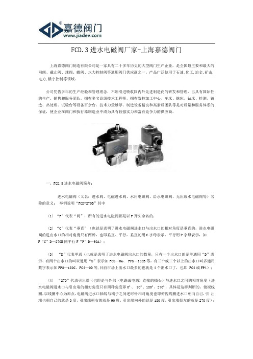
一、FCD.3进水电磁阀简介:进水电磁阀(又名:进水阀、电磁进水阀、水用电磁阀、给水电磁阀、无压放水电磁阀等)名称的意义:举例说明“FCD-270B”其中〈1〉“F”代表“阀”,所有的进水电磁阀都是以F开头命名的;〈2〉“C”代表“垂直”(也就是表明了进水电磁阀进水口与出水口的相对角度是垂直的,进水电磁阀的进出水口的相对角度只有两种,也即垂直、平行,垂直的用C字母表示,平行用P字母表示,如F“C”D—270B同平行F“P”D—90A);〈3〉“D”代表单通(也就是表明了进水电磁阀出水口的数量,只有一个出水口的是单通用“D”表示、有两个出水口的叫双通用“S”表示如FCS—0A、 FPS-180B等,有三个或三个以上的出水口叫多通用数字表示如FP3—180C、FC4—0D等,目前市场上出水口最多的也就是4个出水口了,也即 FC4或FP4);〈4〉“270”代表引出端(也即是与外部〈电路或电源〉连接的插头)与进水口之间的相对角度(进水电磁阀进水口与引出端的相对角度只有四种角度即0º、90º、180º、270º,具体是这样判断的:俯视线圈,以线圈中心为原点,电磁阀进水口轴线与端子之间逆时针相对角度也即俯视线圈进水口朝向自己,引出端也朝自己的就是0度,引出端朝右的就是90度,引出端向外的就是180度,引出端朝左的就是270度);〈5〉“B”是生产工厂自己内部的编号。

增强型
CW3R增强型智能万能式断路器
R
CW3R增强型
智能万能式断路器
前所未有的突破,超长寿命确保更可靠的生命周期,再次在行业中的超越和引领。
CW3R具有超长的机械寿命和电气寿命,机械寿命(免维护)达到3万次,电气寿命达到1.5万次(400V),并满足GB14048.4 AC-3类使用要求。
凭借优越的性能,CW3R增强型万能式断路器更方便各类电气系统的应用选型,无论是对于标准电气配电应用场合,还是对于新型分布式能源电气配电需要,以及风机并网操作、逆变器并网操作的设备应用需要,都可满足其应用要求,并可节约您的费用。
CW3R增强型万能式断路器,特别推出增强型智能控制器ER型,满足多电源网络各类特殊的保护要求,如方向性保护、方向性区域选择性保护、自动同期合闸功能、双重参数整定等。

FLUID CONTROL DIVISIONParker Hannifin Corporation95 Edgewood AvenueNew Britain, CT 06051Telephone (860) 827-2300IOM 304Fax (860) 827-2384 (Rev B)INSTALLATION, OPERATING & MAINTENANCE INSTRUCTIONS3-WAY NORMALLY CLOSED, 3-WAY NORMALLY OPENAND 3-WAY UNIVERSALDIRECT ACTING VALVESSERIES 304GENERAL SAFETY INSTRUCTIONS BEFORE INSTALLATIONFAILURE OR IMPROPER SELECTION OR IMPROPER USE OF THE PRODUCTS AND/OR SYSTEMS DESCRIBED HEREIN OR RELATED ITEMS CAN CAUSE DEATH, PERSONAL INJURY AND PROPERTY DAMAGE.Both the conduit coil and leaded one-piece coil contain a green “grounding” wire that must be secured to a proper ground location.DO NOT cut off the green ground wire. Doing so could negate a proper ground path and leave the valve assembly unprotected or “hot”.This document and other information from Parker Hannifin Corporation, its subsidiaries and authorized distributors provide product and/or system options for further investigation by users having technical expertise. It is important that you analyze all aspects of your application, including consequences of any failure, and review the information concerning the product or system in the current product catalog. Due to the variety of operating conditions and applications for these products or systems, the user, through its own analysis and testing, is solely responsible for making the final selection of the products and systems and assuring that all performance, safety and warning requirements of the application are met.The products described herein, including without limitation, product features, specifications, designs, availability and pricing, are subject to change by Parker Hannifin Corporation and its subsidiaries at any time without notice.Carefully read installation, operation and maintenance procedures prior to installing or servicing valve.Do not use valve as a safety shut-off valve when making repairs. Do not install a valve before depressurizing system down to atmospheric pressure.Care must be taken to ensure that the valve materials selected are suitable for the media being handled. Parker assumes no liability for damage caused by improper material selection.Caution: Do not, at any time, make any alteration or modifications to any valve without the express and written approval of Parker’s Fluid Control Division.DESCRIPTIONThese valves are 3-way direct operated valves. The 304 series valve product line are available as Normally Closed (N.C.), Normally Open (N.O.), or universal (U) valves. The direct acting valves operate with zero pressure differential.Valves may be ordered with either NEMA 2, 4, 4X integrated coils for ordinary locations. Additional solenoid coils and enclosures are offered as described in our catalog.FLUID CODESListed below are the common fluid codes. The codes for the approved fluids for use with each valve are printed on the outside of the individual packaging.CODE FLUIDA - Air or nontoxic, nonflammable gasesAC - AcetyleneG - City gas supplied by public utilieisGA - GasolineHO - Petroleum based oils having viscosities up to 400SSU at 38°F02 No1 and No 2 fuel oils with viscosities lessthan 40SSU at 38°COX - OxygenW Water or other aqueous nonflammable liquidsFor the maximum fluid temperatures, as well asvalve ambientlimitations, check the valve part number on the nameplate and refer to the catalog.TORQUE CHARTINSTALLATION INSTRUCTIONS Installation must be done according to all applicable Safety Codes and Standards and by qualified personnel.Inspect valve prior to installation. Damaged valves oractuators must not be installed.Mounting position and pressure limits: Valves can bemounted directly on piping or by using the two #8-32 UNF threaded holes in the bottom of the valve body for the 1/8” NPT valves. Two #10-32 UNF threaded holes for the 1/4” NPT valves. The valves are designed to operate in any position. The valve may be installed in any line regardless of the direction in which the line runs. However, for optimum life and performance, the valve should be mounted vertically upright so as to minimize wear and reduce the possibility of foreign matter accumulating inside the sleeve area. Line pressure, voltage and frequency must conform to nameplate rating. Allow adequate clearance above valve for removal of coil. WARNING: Do not install a valve whose permitted pressure / temperature ratings are inadequate to meet the operating conditions. Piping: Remove protective closures from the ports. Connect line pressure to the inlet port and apparatus piping to the outlet port. Use of Teflon™ tape, threaded coumpounds or sealants is permissible but should be applied sparingly to male pipe threads only. CAUTION : Do not allow foreign particles, Teflon tape, or thread compound to enter valve. Only the wrench flats provided on the body ports should be used in applying the torque. Ports should not be subjected to excessive torque by use of an oversized wrench, wrench extension or by impacting the wrench handle. Do not use the valve to “stretch” or “align” the pipe. Tightening torque should not exceed 100 in-lbs for 1/8” NPT valves and 175 in-lbs [20,0 Nm] for 1/4” NPT valves. Do not use sleeve or enclosure as a lever when applying torque.Media filtration: For protection of the valve, install a suitable strainer or filter in the inlet side as close to the valve as possible. Dirt or foreign material in the media may cause excessive leakage, wear, or in exceptionalcases, malfunction. Clean periodically depending on service conditions. Lubrication: Lubrication is not required although air linelubrication will substantially increase valve life. Electrical connection: Electrical supply must conform to nameplate rating. Connect coil leads or terminals to the electrical circuit using standard electrical practices in compliance with local authorities and the National Electrical Code. Do not power coil until it has been fitted over sleeve and the retaining nut has been installed to prevent possible coil damage from overheating. WARNING : Turn off electrical power before connecting the valve to the power source. If the coil assembly is located in an inconvenient orientation, it may be reoriented to facilitate installation. Loosen coil assembly nut, rotate coil assembly to desired position, then retighten the retaining nut with an input torque per chart. COIL ASSEMBLY Position coil (as described below) on the sleeve, position and tighten retaining nut into the top of the sleeve assembly using a 5/32” or 5mm hex wrench with an input torque per chart. If the coil orientation needs to be repositioned to meet installation wiring needs, simple loosen the retaining nut usi ng a 5/32” or 5mm hex wrench , then rotate the coil to the required position and tighten the retaining nut. NOTE : The one-piece integrated coil assembly contains top and bottom o-ring seals to prevent moisture ingressioninto the sleeve area. The o-ring seals must be installed correctly for proper functionality. PORT MARKING ARRANGEMENTDe-Energized Energized11 33333One-Piece Integrated Coil. The conduit coil meets NEMA 2, 4, 4X classification for ordinary location requirements. Use suitable electrical cabling and conduit materials and components meeting applicable NEMA recommendations.For both the conduit and leaded one-piece coils, slide one o-ring over and down the sleeve assembly until the o-ring rests on the valve body., Slide the coil over the valve sleeve. Place the second o-ring into the recess located on top of the coil. Affix retaining nut to sleeve and tighten per torque chart. Use suitable electrical cabling for wiring connection.WARNING: Both the conduit coil and leaded one-piece coil contain a green “grounding” wire that must be secured to a proper ground location. The grounding wire is welded to the internal coil frame providing the approved ground path for the total valve assembly.DO NOT cut off the green ground wire. Doing so could negate a proper ground path and leave the valve assembly unprotected or “hot”.One-Piece DIN Coil and various cable option terminations:Loosen cable screw and remove plastic housing from DIN coil. Do not remove the gasket from the DIN spades on the coil. Separate the plastic block from the housing with a small screwdriver to expose the elecctrical terminations. Feed the lead wires through the conduit hub and attach them to the appropriate screw terminal. For electrical connection within the terminal box, use field wire that is rated for 90o C or greater. Snap the plastic block back into place inside the metal enclosure. Replace the cover and hand-tighten the cover screws. Place the gasket over the DIN spades on the coil and press the terminal box and coil together. Secure the terminal box to the coil using the mounting screw provided.Slide one o-ring over and down the sleeve assembly until the o-ring rests on the valve body. Slide the DIN coil over the valve sleeve. Place the second o-ring into the recess located on top of the coil. Affix retaining nut to sleeve and tighten per torque chart.Two-Piece Yoke & Spade Coil with 1/4” tabs: With coil inserted inside of U-shaped metal yoke, slide coil over sleeve. Affix retaining nut to sleeve and tighten per torque chart. Connect spade termination connector to spade tabs on coil.Two Piece Yoke & Molded Leaded 2-Wire Coil: With coil inserted inside of U-shaped metal yoke, slide coil over sleeve. Affix retaining nut to sleeve and tighten per torque chart. Use suitable electrical cabling for wiring connection. Two Piece Grommet Housing & Taped 2 Wire Coil: With the taped coil inserted inside the metallic housing, slide coil over sleeve. Affix retaining nut to sleeve and tighten per torque chart. Use suitable electrical cabling for wiring connection.Coil/enclosure temperature:The direct acting valves are supplied with coils designed for continuous duty service. Normal free space must be provided for proper ventilation. When the coil is energized continuously for long periods of time, the coil assembly will become hot. The coil is designed to operate permanently under these conditions. Any excessive heating will be indicated by smoking and/or odor of burning coil insulation.For the maximum valve ambient conditions, as well as the fluid temperatures, check the valve part number on the nameplate and refer to the product catalog to determine the maximum temperatures.MAINTENANCENote: While the valves are design to operate over millions of cycles, depending on service conditions, fluid being used, filtration, and lubrication, it may be required to periodically clean and/or replace worn components to ensure optimum quality performance. See Disassembly Instructions.CAUTION:Do not expose plastic or elastomeric materials to any type of commercial cleaning fluid. Parts should be cleaned with a mild soap and water solution.If a valve is to be removed from a pipeline carrying hazardous media, the parts of the valve in contact with the hazardous media must be properly cleaned and decontaminated before repairs are performed.DISASSEMBLY INSTRUCTIONSWARNING:Depressurize system and turn off electrical power to the valve before attempting repair. The coil must not be energized unless it is installed on the valve. Otherwise, the coil will overheat and burn out.The valve body need not be removed from the line.CAUTION:When removing or replacing the sleeve assembly, it may be necessary to provide proper support to prevent the valve from rotating thereby causing damage to piping.To remove the coil assembly:Using a 5/32” or 5mm hex wrench, unscrew the top retaining nut of the coil assembly. The coil assembly can be lifted off the sleeve tube.To disassemble the pressure vessel:Use the same 5/32” or 5mm hex wrench turning counterclockwise to remove the sleeve tube. The plunger assembly, return spring and o-ring seal may be removed. Replacement Parts: When ordering replacement parts kits, specify valve number and voltage from nameplate. Parts kits are available for each valve. Parts included in each kit are marked with an asterisk (X). See exploded views.PRESSEURE VESSEL REASSEMBLY INSTRUCTIONSTo reassemble the pressure vessel, refer to exploded view drawings. Parts must be replaced in the order shown.Lubricate o-ring with a mineral oil or equivalent and replace the o-ring into the valve body. Install the plunger and spring into the sleeve. Carefully align threads while installing the sleeve into the body.Tighten the sleeve assembly in the body using the 5/32” or 5mm hex wrench turning clockwise with an input torque per torque chart.COIL REASSEMBLY INSTRUCTIONSWith coil assembly repositioned on the sleeve, position the retaining nut into the top of the sleeve assembly and tighten using a 5/32” or 5mm hex wrench with an input torque of of 25-35 in-lbs [2,9 to 4,0 Nm].LABELINGMODULAR LABELINGFor valves sold modularly, a 2-piece label system is used consisting of a base valve identification label and a coil identification overlay label. The base label is affixed to the coil and the overlay label is placed over the base label provide the complete valve identification.VALVE IDENTIFICATIONAll Parker pressure vessels are identified with a valve label. The label indicates the valve part number, maximum operating pressure differential (MOPD), orifice size and date code.FLUID CONTROL DIV NEW BRITAIN, CT USADATE CODE ORIFICE 1207O 7/64 PRESSURE VESSEL30CC02MV4WATTS 10AC 8.5DCAC 50 PSIDC 50 PSICOIL IDENTIFICATIONAll Parker coil enclosures are identified with a label. The label indicates the coil part number, voltage and frequency.FLUID CONTROL DIV NEW BRITAIN, CT USAVOLTS/HZ24VDCENCL & B4BCOILFULLY ASSEMBLED VALVE LABELINGAll Parker valves are identified with a valve label. The label indicates the valve type and size, maximumoperating pressure differential (MOPD), orifice size and applicable agency approval designations. In addition, the label also specifies the appropriate electrical specifications for agency compliance.FLUID CONTROL DIV NEW BRITAIN, CT USAVALVE NUMBER30CC02MV4B2BVOLTS/HZ 24VDCWATTS 8.5 ORIFICE 7/64 3/32PSI50BAR3CODE0907OPARTS LIST AND COMPONENT DRAWINGRetaining NutComplete Portfolio of Available CoilsDECLARATIONParker’s Fluid Control Division certifies its valve appliance products complies wit h the essential requirements of the applicable European Community Directives. We hereby confirm that the appliance has been manufactured in compliance with the applicable standards and is intended for installation in a machine or application where commissioning is prohibited until evidence has been provided that the machine or application is also in compliance with EC directives.The data supplied in the Parker valve catalogs and general Installation, Operating & Maintenance Instructions are to be consulted and pertinent accident prevention regulations followed during product installation and use. Any unauthorized work performed on the product by the purchaser or by third parties can impair its function and relieves Parker Hannifin of all warranty claims and liability for any misuse and resulting damage.A separate Declaration of Conformity or Manufacturer’s declaration is available upon request. Please provide valve identifica tion numbers and order serial numbers of products concerned.。


一体化三阀组内部结构
一体化三阀组是一种由三个阀门组成的阀门组合,包括一个入口阀门、一个出口阀门和一个旁路阀门。
其中,入口阀门和出口阀门通常采用截止阀,而旁路阀门则采用球阀或针型阀。
这种阀门组合广泛应用于石油、化工等工业领域,用于控制各种物料的流量和压力。
一体化三阀组内部结构由阀体、二个截止阀及一个平衡阀组成。
这种结构使得三阀组具有操作简便、安全可靠、维护方便等优点,已成为工业生产中不可或缺的设备之一。
在实际应用中,三阀组的操作方式应根据工艺流程和生产要求进行选择和调整。
常见的操作方式有:入口阀门打开,出口阀门关闭,旁路阀门关闭;入口阀门关闭,出口阀门打开,旁路阀门关闭;入口阀门关闭,出口阀门关闭,旁路阀门打开等。
此外,三阀组的设计应考虑材质选择、阀门选型、管道布置和安全措施等因素。
同时,了解和掌握三阀组的结构和工作原理有助于正确使用和维护该设备,提高工业生产效率。
以上信息仅供参考,如需一体化三阀组的内部结构图或更多信息,建议访问相关品牌的官网或咨询专业技术工程师。
三位五通电磁换向阀的工作原理
第一次听说有一种电磁换向阀叫“三位五通”,请问:它的结构与工作原理是什么请真正的内行回答。
不要回答那些诸如“二位三通”、“二位四通”之类文不对题的东西。
问题补充:
三位五通电磁换向阀如何实现在动作的过程中停止我讲的“在动作的过程中停止”是指通过电磁阀的控制作用使气缸能在行程中的任意位置上停止,而不是仅指气缸在中间位置上停止。
请行家进一步指教。
最佳答案
三位五通顾名思义,三个工作位置,五个口。
三个位置是指电磁阀的阀芯有三个位置。
三位电磁阀都是有两个线圈的。
我们暂且称之为A和B线圈。
AB都不通电的时候阀芯是一个位置,A通电时阀芯会动作,这是第二个位置,A断电,B通电的时候阀芯的位置是第三个位置。
所以一共三个位置。
请注意三位五通电磁阀有三种,指AB都不通电的时候阀芯的状态不同分为中封,中开和中闭。
你可以看下面的图片现实的是中闭型三位五通阀。
五通就是指五个口,一个进气口,两个气缸口,两个排气口(这两个也可以并成一个)。
补充:如何在动作中停止很简单,就是电磁阀两边全部断电,阀芯在中间位置,如果是中闭的话(就是把气缸两头进气通道堵住),这样气缸两头无法排气就会使气缸停在中间,无法动作,但是由于气缸,电磁阀会有泄露,通常这样无法长时间停在准确位置。
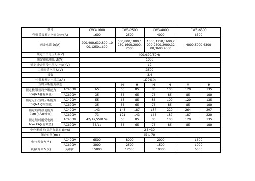
型号CW3-1600 CW3-2500 CW3-4000 CW3-6300 壳架等级额定电流Inm(A)1600 2500 4000 6300额定电流In(A)200,400,630,800,1000,1250,1600 630,800,1000,1250,1600,2000,25001000,1250,1600,2000,2500,2900,3200,3600,40004000,5000,6300额定工作电压Ue(V)400,690/50Hz额定绝缘电压Ui(V)1000额定冲击耐受电压Uimp(kV)12工频耐受电压U(V)3500极数3,4中性极额定电流I N(A)100%In短路分断能力级别M H M H M H额定极限短路分断能力Icu(kA)(有效值)AC400V 65 65 85 85 100 120 135 AC690V 35 55 65 75 85 85 100额定运行短路分断能力Ics(kA)(有效值)AC400V 55 65 85 85 100 120 135 AC690V 35 55 65 75 85 85 100额定短路接通能力Icm(kA)(峰值)AC400V 143 143 187 187 220 264 297 AC690V 73 121 143 165 187 187 220额定短时耐受电流Icw(kA)(有效值)AC400V 42/1s,55/0.5s 65 85 85 100 120 135 AC690V 35/1s 55 65 75 85 85 100全分断时间(无附加延时)(ms)25~30闭合时间(ms)最大70电气寿命*(次)AC400V 6500 8000 2000 1500AC690V 3000 2500 1500 1000 机械寿命*(次)免维护15000 12500 10000 6500有维护30000 25000 20000 13000外形尺寸(mm)W H D W H D W H D W H D抽屉式水平连接3P 后置248 351.5 297 347 438 395 401 438 395 754 475.5 3954P 后置318 351.5 297 442 438 395 514 438 395 980 475.5 395垂直连接3P 后置248 351.5 297 347 438 395 401 438 395 754 475.5 3954P 后置318 351.5 297 442 438 395 514 438 395 980 475.5 395固定式水平连接3P 后置259 320 195 362 395 290 414 395 290 769 395 2904P 后置329 320 195 457 395 290 527 395 290 995 395 290 垂直连接3P 后置259 320 1954P 后置329 320 195*注:根据GB14048.1,术语“寿命”表示电器在修理或更换部件前能完成的操作循环次数的概率。
阀的种类及图例目录阀门的分类 (3)我国目前大多数习惯是按压力和结构种类来区分 (3)按结构种类分主要有: (3)旋塞阀、闸阀、截止阀、球阀 (3)止回阀(包括底阀) (3)节流阀 (3)蝶阀 (3)安全阀 (3)减压阀 (3)疏水器 (4)按用途和作用分类 (4)截断阀类 (4)调节阀 (4)止回阀类 (4)分流阀类 (4)安全阀类 (4)按压力分类真空阀——工作压力低于标准大气压的阀门。
(4)低压阀 (4)中压阀 (4)高压阀 (5)超高压阀 (5)按介质温度分类高温阀——t 大于450'C的阀门。
(5)中温阀 (5)常温阀 (5)低温阀 (5)超低温阀 (5)金属材料阀门 (5)金属阀体衬里阀门 (5)通用分类法 (6)气动调节阀 (6)电动调节阀 (9)自力式调节阀 (11)电磁阀 (12)球阀 (13)蝶阀 (15)闸阀 (17)截止阀 (19)止回阀 (20)旋塞阀 (22)柱塞阀 (22)隔膜阀 (23)减压阀 (24)安全阀 (25)疏水阀 (26)排气阀 (27)排泥阀 (28)呼吸阀 (29)防腐衬氟阀门 (30)在现场我们见到最多的就是阀。
汽包液位三冲量控制、锅炉的燃烧控制等,都是通过阀门开度和关度的大小来控制对象,我们通过算法的目的也是要控制阀门开度和关度的大小,从而达到自动控制。
阀门的用途是广泛的,因此它起的作用也是很大的。
例如:在发电厂中阀门能够控制锅炉和汽轮机的运转;在石油、化工生产中,阀门同样也起着控制全部生产设备和工艺流程的正常运转。
尽管如此,阀门同其它产品比较往往被人们忽视。
例如:在安装机器设备时,人们往往把重点放在主要机器设备方面,如:压缩机、高压容器、锅炉等,这些做法都会使整个生产效率降低或停产、或造成种种其它事故发生,所以我们有必要对阀门进行认识和了解。
阀门的分类阀门产品的种类繁多,说法也不完全统一,有的按用途分(如化工、石油、电站等)、有的按介质分(如水蒸汽、空气阀等)、有的按材质分(如铸铁阀、铸钢阀、锻钢阀等)、有的按连接形式分(如内螺纹、法兰阀等)、有的按温度分(如低温阀、高温阀等)。
上海沈泉泵阀制造有限公司是集研究、开发、生产、销售和服务为一体的泵阀生产企业。
产品涉及工矿企业、农业、城市供水、石油化工、电站、船舶、冶金、高层建筑、消防供水、工业水处理和纯净水、食品、制药、锅炉、空调循环系统等行业领域。
CW旋涡式磁力泵的型号规格及性能参数
CW型磁力驱动旋涡泵也可以被叫做旋涡式磁力泵,这是一种将永磁联轴器的工作原理应用于离心泵的新产品,具有着设计合理、工艺先进、具有全密封、无泄漏、低流量、高扬程、耐腐蚀的特点,该泵其性能基本上已经达到了G外同类产品的先进水平。
该泵广泛应用于化工、制药、石油等行业抽送酸、碱液、油类,稀有贵重液、毒液、挥发性液体,以及循环水设备配套、过滤机配套。
特别是易漏、易燃、易爆的介质。
CW旋涡式磁力泵的型号意义:
CW型磁力驱动旋涡泵性能参数选型表:
好了,以上内容由上海沈泉泵阀制造有限公司为大J提供,希望能够对大J有所帮助。
CNLOK三阀组DCCW3
• 与传统法兰形式的压力/差压变送器直接安装
• 100%严格的密封性测试
• 材质严格保证,304SST、316SST、Monel、Hastelloy可选
• 过程连接1/2-14NPT内螺纹及54X41mm 传统法兰式可选
• 方便对现场仪表进行调校及泄放
• 提供将阀组与压力/差压变送器一体化组装及泄
漏测试的服务
• 通过UKAS-Sira ISO9001:2000 质量管理体系认证
三阀组
CNLOK DC 系列DCCW3三阀组用于和传统法兰式差压变送器
直接安装,也可以通过长螺栓与带共面法兰的3051CD直接安装。
DC系列三阀组有板式(W 式)、法兰管道式(T式)及法兰-法兰式(H式)三种。
DC三阀组仪表接口(出口)的中心距为54mm,直接与差压变送器的高低压接口相连,使用O型环通过螺栓压紧密封。
两个
与过程端相连的截止阀用来截断过程流体与仪表的连接,一个平衡阀在两截止阀中间,用来平衡高低压腔室,以方便对差压变送器进行调零。
在仪表接口及两个截止阀之间的两个泄放堵头(可选)用来排污及校验用途。
W 式三阀组的过程连接为1/2-14NPT内螺
纹.
压力温度等级
阀组标识
所有阀组表面均刻有流向示意图、阀组代码、材质、及承压信息,示例如下:
估计重量:DCCW3----3.3lbs(1.5kg)
典型阀组材质
与过程流体接触部件的材质列表
典型阀组构造:
典型安装图:。