eLog快速入门培训胶片
- 格式:ppt
- 大小:1.58 MB
- 文档页数:115
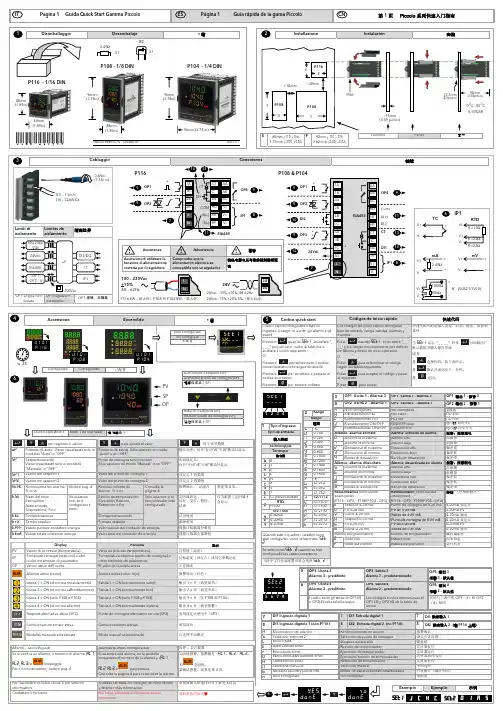
IP6690mm(3.54pollici)12.5mmCablaggio0.4Nm (3.5lb in)0.5 – 1.5mm (16 – 22AWG)OP1 Logica non isolataOP1 OP2 - 4Limiti di isolamento100-230V /24V EIA485 24VdcP1161310s e t 1 ____V 1.0P 11V 1.P 1V 1.0P 10ConfiguratoConfigurado已配置Livello operatore 1Nivel 1 de operador操作等级1Uscita 1 = ON (di norma riscaldamento) Uscita 2 = ON (di norma raffreddamento) Uscita 3 = ON (solo P108 e P104)Uscita 4 = ON (di norma allarme) per regolare il valorepara ajustar el valorPotenza d’uscita. Viene visualizzata solo in modalità "Auto" o "OFF". Potencia de salida Sólo aparece en modo "Auto" o en "OFF" Viene visualizzato solo in modalità Punto de consigna seleccionadoSólo aparece en modo "Manual" o en "OFF" Valor del punto de consigna 1 Valor del punto de consigna 2 Riconoscimento allarme Vedere pag. 4Reconocimiento de alarma Sí o noConsulte la página 4Visualizzato solo se èconfigurato il timerEstado de temporizador: Ejecución, Reinicio, Retención o Fin Sólo aparece si el temporizador está configurado eventosPremere _ _ _" per caricare i valori di fabbrica e codice successivo. Premereper tornare indietroPulse cuando _ _" para cargar los parámetros por defecto Pulse para seleccionar el códigosegún las tablas siguientes.Pulse para aceptar el código y pasaral siguiente. Pulsepara volver.Ridurre il setpoint (SP)Reducir punto de consigna (SP) 031668I S CHA031668ISC/4 CN30076 05/1348mm(1.89in)48mm(1.89in)(1.89in)96mm (3.78 in)Ejemplo 1: Uso de alarmasEs posible usar un máximo de tres alarmas. Se pueden pedir o configurar usando los códigos deinicio rápido (página 1) o los códigos "P" (página 3).Ajuste de umbrales de alarmaEn el nivel 2 de operador, seleccione AL1, AL2 o AL3.Pulse o para fijar el umbral.Reconocimiento de alarmaUna alarma se puede reconocer de tres formas:1. En todos los casos: Pulse para seleccionar Ac.AL. A continuación pulse opara seleccionar YES.2. Utilice la entrada digital 1 o 2 (si está configurada).3. Pulse (si está configurado; consulte el código de configuración P73).Si la alarma persiste, el indicador ALM permanecerá encendido.Las alarmas están configuradas sin retención de manera predeterminada.Ejemplo 2: Uso del temporizadorEs posible configurar un temporizador interno en tres modos de funcionamiento:Parada: Para controlar un proceso en un valor fijo durante un tiempo definido.Retardo: Para activar la potencia de salida después de un tiempo definido.Inicio suave: Para aplicar un límite de potencia durante un tiempo definido.Utilice t.dUr para definir el período de tiempo.En el caso de un temporizador de parada, configure t.thr para iniciar la cuenta atrás cuandoPV esté próximo a SP.En el caso de un temporizador de inicio suave, configure el límite de potencia SS.oP, el umbralSS.SP.Utilice t.St para poner el temporizador en ejecución, retención o reinicio, o para conectarlo auna entrada digital configurada.End parpadeará cuando el temporizador llegue al final. La salida de potencia adoptará el valordefinido por P43.Ejemplo 3: Autoajuste del reguladorFije el punto de consigna en torno a la temperatura normal de funcionamiento.Defina los límites de salida en un valor seguro.Seleccione A.tun en el nivel 2 y póngalo en YES.tunE parpadeará en la pantalla del regulador hasta que finalice el ajuste automático.Ejemplo 4: Monitor de energíaUna estimación del uso de energía se mide en una salida (normalmente calor) que se configuracon P81.Especifique en P82 la potencia de carga nominal (en KW).En los niveles 1 y 2, E.Par mide el consumo energético para lotes individuales y E.tot lo midepara todo el proceso. También es posible personalizarlos para que aparezcan en las líneas 2 y 3de la pantalla usando P74 y P75.Utilice E.rSt en el nivel 2 para poner los valores a cero. E.tot sólo se puede poner a cerodespués de E.Par P71, P72 o P73 permiten personalizar uno de los botones de función o elbotón Página para acceder a este parámetro.例1:操作报警可用的报警达3个。

Quick Start GuideLaser displacement sensor with both analog and discrete (switched) outputsThis guide is designed to help you set up and install the L-GAGE ® LE Laser Gauging Sensor. For complete information on programming, performance, troubleshooting, dimensions, and accessories, please refer to the Instruction Manual at . Search for p/n 175094 to view the manual. Use of this document assumes familiarity withpertinent industry standards and practices.WARNING: Not To Be Used for Personnel ProtectionNever use this device as a sensing device for personnel protection. Doing so could lead to serious injury or death. This device does not include the self-checking redundant circuitry necessary to allow its use in personnel safety applications. A sensor failure or malfunction can cause either an energized or de-energized sensor output condition.Features and IndicatorsPower LED Indicator Analog Output LED Indicator DisplayDiscrete Output LED Indicator Push ButtonsFigure 1. LE Analog Sensor FeaturesThree LED indicators provide ongoing indication of the sensing status.Analog Output LED IndicatorSolid Amber = Displayed distance is within the taught analog output windowOff = Displayed distance is outside the taught analog output windowPower LED IndicatorSolid Green = Normal operation, power On and laser OnFlashing Green (1 Hz) = Power On and laser Off (laser enable mode)Discrete Output LED IndicatorSolid Amber = Discrete Output is On Off = Discrete Output is OffLaser Description and Safety InformationCAUTION: Use of controls or adjustments or performance of procedures other than those specified herein may result in hazardous radiation exposure. Do not attempt to disassemble this sensor for repair. A defective unit must be returned to the manufacturer.Class 2 Laser ModelsCAUTION: Never stare directly into the sensor lens. Laser light can damage your eyes. Avoid placing any mirror-like object in the beam. Never use a mirror as a retroreflective target.For Safe Laser Use - Class 2 Lasers•Do not stare at the laser.•Do not point the laser at a person’s eye.•Mount open laser beam paths either above or below eye level, where practical.•Terminate the beam emitted by the laser product at the end of its useful path.Reference IEC 60825-1:2007, Section 8.2.L-GAGE ® LE250/550 Analog-Discrete Laser SensorsOriginal Document 175093 Rev. E6 November 2015175093Class 2 LasersClass 2 lasers are lasers that emit visible radiation in the wavelength range from 400nm to 700 nm, where eye protection is normally afforded by aversion responses,including the blink reflex. This reaction may be expected to provide adequateprotection under reasonably foreseeable conditions of operation, including the use ofoptical instruments for intrabeam viewing.Figure 2. FDA (CDRH) warning label(Class 2)Class 2 Laser Safety NotesLow-power lasers are, by definition, incapable of causing eye injury within the duration of a blink (aversion response) of 0.25 seconds. They also must emit only visible wavelengths (400 to 700 nm). Therefore, an ocular hazard may exist only if individuals overcome their natural aversion to bright light and stare directly into the laser beam.Class 1 Laser ModelsClass 1 lasers are lasers that are safe under reasonably foreseeable conditions of operation, including the use of optical instruments for intrabeam viewing.Figure 3. FDA (CDRH) warning label(Class 1)Laser wavelength: 650nmOutput: < 0.22mWPulse Duration: 150 µs to900 µsSensor InstallationNOTE: Handle the sensor with care during installation and operation. Sensor windows soiled byfingerprints, dust, water, oil, etc. may create stray light that may degrade the peak performance of the sensor. Blow the window clear using filtered, compressed air, then clean as necessary using 70%isopropyl alcohol and cotton swabs or water and a soft cloth.Sensor OrientationCorrect sensor-to-object orientation is important to ensure proper sensing. See the following figures for examples of correct and incorrect sensor-to-object orientation as certain placements may pose problems for sensing distances.Figure 4. Orientation by a wall IncorrectCorrectFigure 5. Orientation in an opening IncorrectCorrect Figure 6. Orientation for a turning object - Tel: +1-763-544-3164P/N 175093 Rev. EIncorrectCorrectFigure 7. Orientation for a height differenceIncorrectCorrect Figure 8. Orientation for a color or lusterdifferenceSensor Mounting1.If a bracket is needed, mount the sensor onto the bracket.2.Mount the sensor (or the sensor and the bracket) to the machine or equipment at the desired location. Do nottighten at this time.3.Check the sensor alignment.4.Tighten the screws to secure the sensor (or the sensor and the bracket) in the aligned position.Wiring Diagrams+–* User-configurable PNP/NPN settingFigure 9. Analog Current Model+–* User-configurable PNP/NPN settingFigure 10. Analog Voltage ModelKey11 = Brown2 = White3 = Blue4 = Black5 = GrayDisplayFigure 11. LE550 Display in Run ModeThe display is a 2-line, 8-character LCD. The main screen is the Run mode screen, which shows the real-time distance measurement and the analog output measurement.ButtonsUse the sensor buttons Down , Up , Enter , and Escape to program the sensor and to access sensor information.P/N 175093 Rev. E - Tel: +1-763-544-31643Down and Up ButtonsPress Down and Up to:•Access the Quick Menu from Run mode•Navigate the menu systems•Change programming settingsWhen navigating the menu systems, the menu items loop.Press Down and Up to change setting values. Press and hold the buttons to cycle through numeric values.After changing a setting value, it slowly flashes until the change is saved using the Enter button.Enter ButtonPress Enter to:•Access the Sensor Menu from Run mode•Access the submenus•Save changesIn the Sensor Menu, a check mark in the lower right corner of the display indicates that pressing Enteraccesses a submenu.Press Enter to save changes. New values flash rapidly and the sensor returns to the parent menu.Escape ButtonPress Escape to:•Leave the current menu and return to the parent menu•Return to Run mode from the Quick MenuImportant: Pressing Escape discards any unsaved programming changes.In the Sensor Menu, a return arrow in the upper left corner of the display indicates that pressing Escapereturns to the parent menu.Press and hold Escape for 2 seconds to return to Run mode from any menu or remote teach.Sensor ProgrammingProgram the sensor using the buttons on the sensor or the remote input (limited programming options).From Run mode, use the buttons to access the Quick Menu and the Sensor Menu. See Quick Menu on page 5, Sensor Menu (MENU) on page 6, and the instruction manual (p/n 175094) for more information on the options available from each menu. For TEACH options, follow the TEACH instructions in the instruction manual.In addition to programming the sensor, use the remote input to disable the buttons for security, preventing unauthorized or accidental programming changes. See the instruction manual for more information.from Run ModeAccess Quick MenuAccess Sensor MenuSee Figure 13 on page 5See Figure 14 on page 6Figure 12. Accessing the LE Menus - Tel: +1-763-544-3164P/N 175093 Rev. EQuick MenuThe sensor includes a Quick Menu with easy access to view and change the analog and discrete output switch points.Access the Quick Menu by pressing Down or Up from Run mode. When in the Quick Menu, the current distance measurement displays on the first line and the menu name and the analog value alternate on the second line of thedisplay. Press Enter to access the switch points. Press Down or Up to change the switch point to the desiredvalue. Press Enter to save the new value and return to the Quick Menu.Spt2 not available unless inWindow ModeFigure 13. Quick Menu Map (Window Mode)P/N 175093 Rev. E - Tel: +1-763-544-31645Sensor Menu (MENU)Access the Sensor Menu by pressing Enter from Run mode. The Sensor Menu is also accessible from the Quick Menu: navigate to MENU and press Enter. The Sensor Menu includes several submenus that provide access to view and change sensor settings and to view sensor information.Top Menu Sub MenusLE Series User InterfaceFigure 14. LE550 Sensor Menu Map (Analog Models) - Tel: +1-763-544-3164P/N 175093 Rev. ESpecificationsSupply Voltage (Vcc)12 to 30 V dcPower and Current Consumption, exclusive of loadNormal Run Mode: 1.7 W, Current consumption < 70 mA at 24V dc Supply Protection CircuitryProtected against reverse polarity and transient overvoltages Sensing BeamClass 2 laser models: visible red, 650 nm Class 1 laser models: visible red, 650 nmSensing RangeLE250: 100 mm (3.94 in) to 400 mm (15.75 in)LE550: 100 mm (3.94 in) to 1000 mm (39.37 in)Output ConfigurationAnalog output: 4 to 20 mA or 0 to 10 V, depending on model Discrete output rating: Discrete NPN/PNP is user-configurable Output RatingsDiscrete Output: 100 mA maximum (protected against continuous overload and short circuit)OFF-state leakage current—PNP: < 10 µA at 30 V OFF-state leakage current—NPN: < 200 µA at 30 VOutput saturation voltage—PNP outputs: < 3 V at 100 mA Output saturation voltage—NPN outputs: < 1.6 V at 100 mA Analog current output (LE...I Models):1 k Ω max. @ 24 V;max. load resistance = [(Vcc-4.5)/0.02 Ω]Analog voltage output (LE...U Models): 2.5 k Ω min. load resistanceDelay at Power Up2 sMeasurement/Output RateClass 2 laser models: < 1 msClass 1 laser models (fast): < 1 msClass 1 laser models (std/med/slow): < 2 ms Ambient Light ImmunityClass 2 laser models: > 10,000 lux Class 1 laser models: > 5,000 luxMinimum Window Size, Analog and DiscreteLE250: 1 mm (0.039 in)LE550: 10 mm (0.39 in)BoresightingLE250: 4 mm radius at 400 mm LE550: 1 cm radius at 1 m Remote InputAllowable Input Voltage Range: 0 to VccActive Low (internal weak pullup—sinking current):· High State > 4.3 V at 740 µA max.· Low State < 1.3 V at 800 µA max.Active High (internal weak pulldown—sourcing current):· High State > 4.3 V at 1.7 mA max.· Low State < 1.3 V at 1.6 mA max.Analog ResolutionLE250: 100 mm to 250 mm: Less than 0.02 mm LE250: 250 mm to 400 mm: Less than 0.2 mm LE550: 100 mm to 600 mm: Less than 0.5 mm LE550: 600 mm to 1000 mm: Less than 1 mmAnalog LinearityLE250: Linearity is the less of Accuracy or 0.3% of full scale range (± 0.9 mm) at any given distanceLE550: Linearity is the lesser of Accuracy or 0.5% of full scale range (± 4.5 mm) at any given distance Maximum Torque2 N·m (17.7 in-lbs)RepeatabilitySee Performance Curves Temperature EffectSee Performance Curves AccuracySee Performance Curves ConstructionHousing: die-cast zinc Window: acrylicVibration/Mechanical ShockAll models meet Mil. Std. 202 G requirements method 201A.Also meets IEC 60947-5-2.Typical Beam Spot Size 1xyBeam Spot PatternResponse Timeσ measured valueP/N 175093 Rev. E - Tel: +1-763-544-31647Environmental RatingIEC IP67, NEMA 6Operating ConditionsTemperature: −20 °C to +55 °C (−4 °F to +131°F)Humidity: 90% at +55 °C maximum relative humidity (non-condensing)Storage Temperature−30 °C to +65 °C (−22 °F to +149 °F)Application NoteFor optimum performance, allow 10 minutes for the sensor to warm upCertificationsIndustrial Control Equipment 3TJJUL Environmental Rating: Type 1Required Overcurrent ProtectionWARNING: Electrical connections must be made by qualifiedpersonnel in accordance with local and national electrical codes and regulations.Overcurrent protection is required to be provided by end product application per the supplied table.Overcurrent protection may be provided with external fusing or via Current Limiting, Class 2 Power Supply.Supply wiring leads < 24 AWG shall not be spliced.For additional product support, go to .Performance Curves100200300DISTANCE (mm)R E P E A T A B I L I T Y ( ± m m )400Figure 15. Repeatability (90% to 6% reflectance)123456782000DISTANCE (mm)R E P E A T A B I L I T Y ( ± m m )4006008001000Figure 16. Repeatability (90% to 6% reflectance) - Tel: +1-763-544-3164P/N 175093 Rev. E00.10.20.30.40.50.60.70.90.81.0100200300DISTANCE (mm)A c c u r a c y ( ± m m )400Figure 17. Accuracy (90% to 6% reflectance)12345679810200DISTANCE (mm)A c c u r a c y ( ± m m )4006008001000Figure 18. Accuracy (90% to 6% reflectance)0.1500.1000.1250.0750.0500.0250.0300100200300400DISTANCE (mm)T e m p e r a t u r e E f f e c t (± m m / °C )Figure 19. Temperature Effect0.60.40.50.30.20.10200DISTANCE (mm)T e m p e r a t u r e E f f e c t (± m m / °C )4006008001000Figure 20. Temperature EffectBanner Engineering Corp. Limited WarrantyBanner Engineering Corp. warrants its products to be free from defects in material and workmanship for one year following the date of shipment. Banner Engineering Corp.will repair or replace, free of charge, any product of its manufacture which, at the time it is returned to the factory, is found to have been defective during the warranty period. This warranty does not cover damage or liability for misuse, abuse, or the improper application or installation of the Banner product.THIS LIMITED WARRANTY IS EXCLUSIVE AND IN LIEU OF ALL OTHER WARRANTIES WHETHER EXPRESS OR IMPLIED (INCLUDING, WITHOUT LIMITATION,ANY WARRANTY OF MERCHANTABILITY OR FITNESS FOR A PARTICULAR PURPOSE), AND WHETHER ARISING UNDER COURSE OF PERFORMANCE, COURSE OF DEALING OR TRADE USAGE.This Warranty is exclusive and limited to repair or, at the discretion of Banner Engineering Corp., replacement. IN NO EVENT SHALL BANNER ENGINEERING CORP. BE LIABLE TO BUYER OR ANY OTHER PERSON OR ENTITY FOR ANY EXTRA COSTS, EXPENSES, LOSSES, LOSS OF PROFITS, OR ANY INCIDENTAL,CONSEQUENTIAL OR SPECIAL DAMAGES RESULTING FROM ANY PRODUCT DEFECT OR FROM THE USE OR INABILITY TO USE THE PRODUCT, WHETHER ARISING IN CONTRACT OR WARRANTY, STATUTE, TORT, STRICT LIABILITY, NEGLIGENCE, OR OTHERWISE.Banner Engineering Corp. reserves the right to change, modify or improve the design of the product without assuming any obligations or liabilities relating to any product previously manufactured by Banner Engineering Corp. - Tel: +1-763-544-3164。

通过速度和简化重新设计测试和测量安全注意事项在使用本产品和任何相关仪器之前,请先阅读以下安全注意事项。
虽然一些仪器和附件通常在无害电压下使用,但是也可能出现对人体有害的情况。
本产品应由能辨别电击危险且熟悉避免潜在伤害的必要安全注意事项的合格人员使用。
使用此产品之前请仔细阅读并遵守所有的安装、操作和维护信息。
有关完整的产品规格,请参阅用户文档。
若以没有指定的方式使用产品,可能丧失产品保修所提供的保障。
产品的用户类型有:责任主体,是负责使用和维护机器,确保在设备规格和运行限制范围内使用设备,并确保操作人员经过充分培训的个人或小组。
操作人员,是负责使用产品特定功能的人员。
他们必须接受过电气安全流程和正确操作仪器方面的培训。
应当采取保护措施,防止他们遭到电击和触碰到危险的带电电路。
维护人员,负责产品日常维护以保持仪器运转正常,例如,设置线路电压或更换耗材。
用户文档中描述了维护步骤。
这些步骤都清楚描述了操作人员是否能够执行它们。
如果不能,那么只能由服务人员来执行这些操作。
服务人员,接受过培训,可操作带电电路,执行安全安装并修理产品。
只有受过正确训练的服务人员才能执行安装和服务流程。
美国吉时利仪器(Keithley Instruments) 公司的产品专门设计用于测量、控制和数据输入/输出连接等电气信号,而且不能直接连接到电网电压或具有瞬时高电压的电压源上。
Measurement Category II(引自IEC 60664 标准)连接要求针对本地交流电网连接经常发生的高瞬时电压采取保护措施。
某些吉时利测量仪器可以连接到电网上。
这些仪器将会标记为Category II 或更高级别。
除非在仪器规格、操作手册和仪器标签中明示允许,否则不要将任何仪器连接到电网上。
存在电击危险时,一定要小心谨慎。
电缆连接器插头或测试装置上可能存在致命电压。
美国国家标准学会(ANSI) 规定,超过30 V RMS、42.4V峰值或60 V DC 的电压水平存在电击的危险。
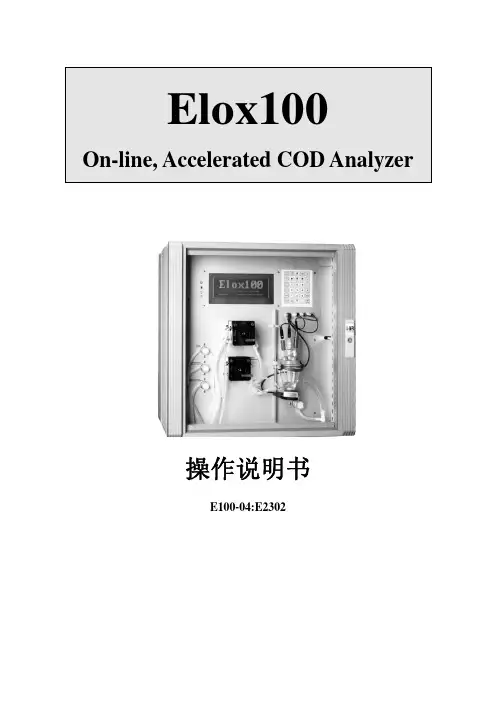
Elox100On-line, Accelerated COD Analyzer操作说明书E100-04:E2302LAR公司保留有关权利。
保留对于技术提升所做的改变。
未经LAR公司允许,这本手册的任何部分都不可以复印或者翻录。
本手册中所有提及的注册商标已经得到公认。
目录1 Elox操作原理 (1)1.1 COD分析 (1)1.2 Elox正视图 (2)1.3 Elox俯视图 (3)1.4 Elox管路图 (4)1.5 Elox电极 (5)1.6 Elox键盘 (5)1.7 显示屏快捷键 (6)2 安装和启动准备 (8)2.1 安全操作注意事项及说明 (8)2.2 安装地点 (8)2.2.1 周边条件 (8)2.2.2 电源 (8)2.2.3 样品供应 (9)2.2.4 排水 (10)2.2.5 软水 (10)2.3 启动准备 (11)2.3.1 Elox的墙挂式安装 (11)2.3.2 电极安装 (11)2.3.3 管道安装 (12)2.3.3.1 管夹阀管路连接、 (12)2.3.3.2 蠕动泵管路连接 (13)2.3.4 化学物质 (14)2.3.5 水力连接 (15)2.36 电器连接(模拟输出,继电器,数字输入线) (15)3 如何使用Elox (18)3.1 分析仪的启动 (18)3.1.1 操作软件的启动 (18)3.1.2 操作软件上的一般标记 (18)3.1.3 完整的帮助系统 (21)3.1.4 填充管道系统 (22)3.2 Elox的设置 (23)3.2.1 测量参数显示 (23)3.2.2 系统设定 (24)3.2.2.1测量频率 (25)3.2.2.2 校正/测量范围 (26)3.2.2.3 试剂消耗指示 (26)3.2.2.4 警报设点 (27)3.2.2.5 打印机 (27)3.2.2.6 保存操作参数 (28)3.2.2.7 打印操作参数 (28)3.3 模拟输出和继电器 (28)3.3.1 模拟输出 (28)3.3.1.1 检查模拟输出 (31)3.3.2 设置并检查继电器 (32)3.3.2.1 设置继电器 (32)3.3.2.2 检查继电器 (34)3.4 设置日期和时间 (35)3.5 校正Elox (35)3.6 运行模式 (38)3.6.1 要求 (38)3.6.2 开始运行模式 (38)3.6.3 测量数据库 (39)3.6.4 测量过程中的注意事项 (39)3.6.5 状态屏 (40)3.6.5.1 查看测量信号 (41)3.6.5.2 显示当前操作参数 (42)3.6.6 显示24小时曲线 (42)3.6.6.1 在曲线中回扫测量值 (42)3.6.7 在运行模式下查看自动标准结果 (43)3.6.8 列表显示测量结果 (43)3.6.8.1 下载测量数据到软盘 (45)3.6.9 在运行模式下访问内置数据库 (45)3.6.10 终止运行模式 (46)3.7 测量参数显示 (46)3.7.1 实验室测量的取样 (47)3.7.2 输入水流名称 (48)3.7.3 输入名称和单位 (49)3.7.4 输入实验室数据 (49)3.7.4.1 自动线性模拟 (50)3.7.4.2 用零截距拟合一条直线 (51)3.7.4.3 拟合参数的外部确定 (52)3.7.4.4 复合线 (53)3.8 服务菜单 (53)3.8.1 执行每周的维护和检查 (53)3.8.2 填充管路系统 (54)3.8.3 填充测量槽 (54)3.8.4 排空测量槽 (54)3.8.5 校正Elox (54)3.9 数据分析 (55)3.9.1 内部数据库操作 (55)3.9.1.1 选择测量数据文件 (55)3.9.1.2 图形显示测量文件 (56)3.9.1.3 以表格方式显示数据文件 (56)3.9.2 操作日志 (57)3.9.3 查校正功能 (58)4 Elox100维护 (59)4.1 开始运行模式 (59)4.2 短期关机后开始运行模式 (59)4.3 每周的保养维护 (59)4.4 每月的维护保养 (60)4.5 季度维护保养 (60)4.6 短期关机程序 (61)4.7 长期关机程序 (61)4.8 维护任务描述(以字母为序) (61)4.9 备用及保养元件 (69)5备件和可选项 (70)5.1 样品检测和远程控制 (70)5.2 串行端口RS232 (71)6 Elox的特点 (73)6.1 水中有机物的电化学测量 (73)6.2 Elox测量系统 (73)7 故障分析 (75)7.1 故障排除 (75)7.2 故障分析索引 (77)8 技术信息 (79)8.1 技术数据 (79)1 Elox操作原理1.1 COD分析Elox 系列COD分析仪可以容易、自动地检测有机物含量。
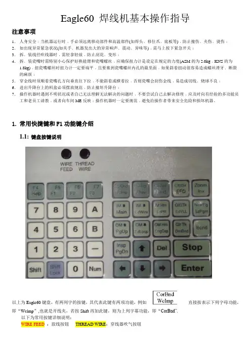
Eagle60 焊线机基本操作指导注意事项1.人身安全﹕当机器运行时﹐手必须远离移动部件和高温部件(如焊头﹑移位爪﹑底板等)﹐防止撞伤﹑夹伤﹑烫伤﹔2.如出现异常紧急状况(如夹手﹑机器发出大的异常响声﹑震动﹑异味等)﹐需马上按下紧急开关﹔3.拆﹑装线径吹线器时﹐需轻拿轻放﹐防止刮花﹑变形﹔4.拆﹑装瓷嘴时需特别小心保护好换能臂和瓷嘴螺丝﹐应确保扭力计是设定在规定的力度(ASM的为2.0kg﹐KNS的为1.8kg)﹐扭瓷嘴螺丝时扭力计一定要端平﹐且要塞到瓷嘴螺丝内孔的最里面﹐如果斜着扭动很容易造成螺丝滑牙﹑断裂的麻烦﹔5.穿金线时须顺着瓷嘴孔方向垂直往下拉﹐不能斜着或横着拉﹐否则瓷嘴会刮伤金线﹐易造成切线﹑烧球不良﹔6.进出升降台上的料盒必须摆放规范﹐防止撞坏升降台﹔7.操作机器时遇到不明状况或者自己无法理解无法解决的问题时﹐不要尝试自己去解决修理﹐应及时向有经验的多功能员工和老员工请教﹐或者向车间ME反映﹔操作机器时一定要规范﹐避免给操作者带来安全危险和损坏机器。
1.常用快捷键和F1功能键介绍1.1:键盘按键说明以上为Eagle60键盘,有两列字的按键,其代表此键有两项功能,例如直接按表示下列字母功能,即“Wclmp”,也就是开线夹,若按Shift再加此键,则为上列字幕功能,即“CorBnd”.以下为常用按键详细说明:WIRE FEED:放线按钮THREAD WIRE:穿线器吹气按钮:打开/关闭线夹:打开照明打光:打开压板:烧球:单元进位:进料盒上升一格:进料盒下降一格:出料盒上升一格:出料盒下降一格:更换进料盒更换出料盒:修改焊点位置:切线/烧球:清除轨道:跳到上一页:跳到下一页:直接切换到自动焊线菜单:输入选择第几条线:删除键:停止键:确认键:为功能键1.2: F1功能键F1功能键,按此键后输入相应数字所代表的功能:F1--4 :切线﹔F1--6 :测量两点之间的距离F1--17:更换瓷嘴﹔F1--18:超声功率输出,在瓷嘴有堵塞时候可使用﹔F1--24:打开轨道﹔F1--110:焊头马达复位﹔F1--100:查看系统版本信息﹔F1—15:进入工程菜单,密码2002﹔F1—902:空打﹐只模拟焊线动作2:焊线参数2.1:查看焊线参数1400:选择第几条线1401:该条线的线弧类型1407:该条线的第1/2焊点时间1408:该条线的第1/2焊点功率1409:该条线的第1/2焊点压力2.2:修改焊线参数焊线参数一般可在41“Base Parrmeter”菜单修改,但考虑到同一个碗杯里固不同的芯片,芯片电极参数有可能使用不同参数,所以一般不在这个菜单修改。

自动焊线机(EAGLE-60)培训教材培训目的:让设备操作人员掌握正确的设备操作方法,以提升产品质量及生产效率。
培训对象:自动焊线机操作人员。
培训设备型号:EAGLE-60培训内容:一、开机:1、先开气、再开电源(气压4-6Kg/cm2,电压220V);2、打开显示器电源开关3、电源打开后,机台系统进行自检,送料马达搜索原位,大约5分钟后自检完毕,按ENTER键进入待机状态。
二、程序设定:2.1 启动机器,进入主菜单"Teach"项,选择第5项"Delete program",按"Enter"键,提示"Sure to delete program?",按A键,刪除程序,显示"Reset parameter windows?",按"stop"键退出(如按A键,则所有参数将变更)。
2.2 进入主菜单第3项"Teach program",选择第1项"Teach Alignment",按Enter键显示"pairs of align point2",按"Enter"键确认,左屏幕显示"Dieo 1 lead"滚动操作球,将焊头移至左侧第6个支架单元左上角位置,按enter键输入第1个支架对点,将焊头移至右侧第1个支架单元右上角位置,按Enter键确认.2.3 显示"Die 1 Die"移动焊头至第1个Die位置处,使屏幕十字线与晶片电极中心对准,按Enter键2次,输入2个对点;焊头自动跳至第6个支架单元处,要求做支架2nd焊点PR识別,右屏幕显示裝载PR菜单,其中第6项"PR Lead/search mode选择PR识別模式,Binary/Greylvl為黑白与灰度识别常用模式,根据需要进行选择使用.键盘数字键:2=coax , 3=side , 4=Bcoax,分別调节同轴光,侧光及同轴蓝光,1=Threshold调节图象黑白对比度,按一次方向键,增加光亮速度调整;图象调节以清晰为准,按Enter键装载,同理装载晶片PR.2.4 显示"NO.of wire 300"输入"1"条线,按Enter键,选择第4项PRsupport mode将"Both"改为"none",选择0项"Get Bond point",移动操作球,使十字线与晶片电极中心对准,按Enter键一次,输入第1st焊点位置;移动焊动至第2nd焊点焊的位置,按Enter确认之后连续4次退出至主画面,选择第2项step/Repeat,将None改为Ahead 模式,显示 No of repeat rows 1,输入1,显示 No of repeat cols 1,输入7,按Enter键,左屏幕显示"Teach on upper right unit,Enter a lead align pt"将焊头移至最右边第1个支架单元左上角处,按Enter,之后至支架第7单元处,修正支架,使支架与十字线左上角对齐,按Enter键确认结束程序编辑。

Violino™ DPSS全风冷半导体泵浦激光标记系统前言为加强对高速成长的亚洲市场的全方位支持,LASERVALL(镭射谷)集团2003年在中国深圳设立了“镭射谷科技(深圳)有限公司,为中国首家外商独资的工业激光应用系统高科技企业。
镭射谷科技(深圳)有限公司以LASERVALL先进的激光专有技术为核心,针对中国的工业特点和要求,对LASERVALL的系列产品进行进一步的技术开发、研制和生产。
镭射谷科技(深圳)有限公司的设立,极大地加强了中国境内用户的技术支持和服务。
镭射谷科技(深圳)有限公司的产品除在中国市场销售外,也批量销售到世界各地的市场。
LASERVALL公司拥有VIOLINOTM (微欧力诺™)品牌的红外光、绿光、紫光全频谱系列的光纤耦合全固态风冷半导体激光系统,公司产品技术领先、性能优越、应用广泛,在激光标记等工业应用领域享有世界声誉。
LASERVALL的产品已经全部通过国际权威的ISO9001的认证值得注意的是近年来发展起来的半导体激光器。
半导体激光器具有小型化、频率极高、与光纤良好耦合、易于调制等优良特性,因而具有广阔的应用前景。
要在不同产业中广泛应用激光制造技术,很大程度上要依赖于激光加工系统的性能与工艺。
欧、美、日及意大利一些国家在新光源、加工系统及工艺等方面的研究与开发就从未降温过。
随着激光工作物质的研究与开发、器件与单元技术的改进和创新,以高性能、宽波段、大功率为特征的激光取得了蓬勃的发展,如紫外光输出的KrF、ArF 准分子激光器、倍频激光器等。
尤其是高功率光纤激光的出现,使激光制造的移动式定位加工变得更加便利。
Violino™ DPSS全风冷半导体泵浦激光标记系统安装要求激光系统的现场安装要求:电源,接地,温度,湿度,电磁干扰,振动,水源,气源(1)、场地要求:镭射机应尽量选择安装在不小于10m2的独立封闭的操作室内。
地面水平、硬实、防震,门口粘贴激光防护标识。
如安装在流水线上,则需要根据现场情况,落实激光防护措施,包括粘贴激光防护标识。
ASM Eagle60 PM 手册中文版(免收金币)Eagle60 維修保養培訓手冊目錄目錄.第 1 章工件台模塊.............................................................................................................. 1-.接地之檢查.....................................................................................................................................1-1加熱器之設定及校對.......................................................................................................................1-5加熱器電阻之檢查...........................................................................................................................1-6重置真空感應器...............................................................................................................................1-6升降台之檢查及調整(XYZ 方向) ......................................................................................................1-7後軌道啤鈴彈簧力度之檢查.............................................................................................................1-9引線框架在軌道滑動力度之檢查......................................................................................................1-9預熱塊高度之檢查及調整..............................................................................................................1-10後焊塊高度之檢查及調整..............................................................................................................1-11加熱塊高度之檢查及調整..............................................................................................................1-12加熱塊水平之檢查及調整..............................................................................................................1-13窗式夾具支架之檢查及調整...........................................................................................................1-14加熱塊Y 軸之檢查及調整..............................................................................................................1-16加熱塊方位之檢查及調整..............................................................................................................1-17索引爪鉗之設定.............................................................................................................................1-18工件台線圈之更換.........................................................................................................................1-19第 2 章調整及校對.............................................................................................................. 2-.線夾位置之檢查...............................................................................................................................2-1線夾縫隙之檢查...............................................................................................................................2-2線夾力度之校對...............................................................................................................................2-3焊頭位置之校對...............................................................................................................................2-6焊頭起始彈簧力度之檢查................................................................................................................2-8焊接力度之校對(感應器) .................................................................................................................2-9FORCE RATIO ADJUSTMENT.............................................................................................................2-12線拉緊器之清潔.............................................................................................................................2-14打火杆裝備之拆除及重新裝配.......................................................................................................2-15光学之設定...................................................................................................................................2-17換能器阻力之檢查.........................................................................................................................2-20線盤之設定...................................................................................................................................2-21線盤裝備之清潔.............................................................................................................................2-22添加器之更換及設定.....................................................................................................................2-23Eagle60 維修保養培訓手冊目錄第 3 章X. 工件台模塊......................................................................................................... 3-.X 及Y 軸線圈之更換及調整.............................................................................................................3-1X 及Y 軸加油及磨擦力測試之檢查..................................................................................................3-5X 及Y 線性馬達之更換及調整.........................................................................................................3-6X 及Y 馬達歸位及平行度之檢查及調整...........................................................................................3-7第 4 章線性編碼器之鑑定................................................................................................... 4-.X 及Y 線性編碼器之檢查及鑑定......................................................................................................4-1第 5 章機器之設定.............................................................................................................. 5-.光学系統基準點(攝像機偏距)..........................................................................................................5-1焊尖偏距........................................................................................................................................5-2 焊點中心........................................................................................................................................5-3 焦距偏離中心.................................................................................................................................5-3接觸搜索........................................................................................................................................5-4 圖像識別系統設定...........................................................................................................................5-4Eagle60 維修保養培訓手冊第1 章. 工件台模塊第 1 章. 工件台模塊接地之檢查.量測步驟. 圖示.以下(1)~(7)需將焊機的電源關掉、拔掉Monitor 電源線及拔掉SG (Spark Generator) 前面的白線(Wire Clamp):(1) 邏輯接地與基座接地.OPENEagle60 維修保養培訓手冊第1 章. 工件台模塊量測步驟. 圖示.(2) Window Clamp 接地與Wire(3) Window Clamp 接地與Wire Clamp 電容值<200pF(4) 將SG 前面的白線(Wire Spool) 與SG 後面的黑線(Ref) 電容值<200pF(5) Wire Clamp 的螺絲與Wire(6) Window Clamp 接地與SG 的接地.SHORTEagle60 維修保養培訓手冊第1 章. 工件台模塊量測步驟. 圖示.(7) Bond Head 與基座.SHORT以下(8)~(11)先將SG 前的Wire Clamp 、WireSpool 的線插回。
eCognition培训教材易康eCognition培训教程目录1.多尺度分割.11.1创建一个新工程..21.2执行多尺度分割..51.3创建多重影像对象层101.4编辑均质标准..141.5利用专题层..162.分类..202.1利用昀邻近分类器进行分类..242.2利用隶属度函数分类302.3 利用继承和组层次结构372.4 创建一个复杂的类层次结构472.5 利用掩模技术及类间相关特征.512.6 基于分类的分割..573.样例工程..623.1创建一个多层工程62易康ECOGNITION工作流程..74天目创新 //0>. 易康eCognition培训教程欢迎学习易康eCognition培训指南,这个培训指南有三个模块,每个模块下的教程您都可以在指导者的帮助下练习。
教程的内容是基于日常工作中的常见问题而设计的,以易康eCognition关键应用和特征为范例,对完成基本的处理提供指导。
培训指南此指南一般是在德国 Definiens-Imaging 公司派出的专业指导者的指导下使用。
所有的指导者都是地学和易康 eCognition软件方面的专家,可以在培训过程中随时回答您提出的任何问题。
在教程结束后,您可以将培训教程带走,如果您乐意,您可以在页面上做笔记,这样有助于以后理解。
此指南仅限于易康 eCognition软件的核心应用部分。
在接受培训前,学生须对遥感基础知识进行自行掌握。
模块培训分为以下三部分,进行从分割到分类的全程讲授。
第一部分: 分割第二部分: 分类第三部分: 样例工程教程这个指南中的每一个模块都包含了一系列的手动练习,帮您熟悉软件和样例数据。
教程会有简要的介绍,紧接着再一步步地进行操作练习。
数据这个指南中的所有的教程都使用提供给您的样例数据。
培训完后,您可以利用指导者提供给您的样例数据重新练习一下。
请等指导者介绍完教程材料后再进行模块的练习。
开始练习接下来的教程,您就有机会利用易康 eCognition的一些工具进行练习了。